Note: Descriptions are shown in the official language in which they were submitted.
10544P0197CA01 CA 02561199 2006-09-22
- 1 -
Mounting arranctement and method of mounting elements on the inner lining of
refrigerators and/or freezers and method of producing such mounting
arrangement
This invention relates to a method of producing a mounting arrangement for
mounting elements, in particular pull-out rails, on the plastic inner lining
of a
thermally foam-insulated wall of a refrigerator and/or freezer, a mounting
arrangement and a mounting method for mounting elements on the inner lining of
a thermally foam-insulated wall of a refrigerator and/or freezer, and a
refrigerator
andlor freezer with pull-out rails which are mounted on the inner lining by
means of
such mounting arrangement.
Especially in the construction of refrigerators andlor freezers, thin-walled
inner
linings made of plastics are used as inner and outer walls, the space between
inner lining and outer wall being thermally insulated by means of foam which
is
foamed between the walls. On the inner wall, e.g. rails for supporting trays
or other
fastening elements are mounted. When mounting heavier elements, stability
problems arise due to the thin-walled design of the inner (fining, when e.g. a
corresponding fastening element is screwed into the inner lining.
For mounting such parts in the cooling chamber, it is known to provide
separate
mounting plates on the back of the inner wall, which can, for instance, also
be
foamed in. The element to be mounted is then screwed to such mounting plates
by
means of screws extending through the inner lining. In the known solution, the
manufacturing effort therefore is very high. In addition, the inner lining
must be
pierced on one or more points, which impairs the quality of the thermal
insulation.
It is the object of the present invention to provide methods of producing a
mounting arrangement, mounting methods, a mounting arrangement, and a
refrigerator and/or freezer, by means of which a safe and easy mounting of
elements on the plastic inner lining of a refrigerator and/or freezer wall is
made
possible. This object is solved by manufacturing methods with the features as
stated in claim 1 or claim 2, by a mounting method with the features as stated
in
CA 02561199 2006-09-22
-2-
claim 6 or 7, by a mounting arrangement with the features as stated in claim
10,
and by a refrigerator and/or freezer with the features as stated in claim 16.
The
sub-claims are directed to advantageous aspects.
In the method of the invention, the outer contour of the element to be mounted
is
at least partly reproduced in the plastic inner wall of the refrigerator
and/or freezer.
In this way, a safe retention of the element to be mounted is ensured. Without
additional screw connections or fastening elements, the element to be mounted
is
already supported and retained in the inner wall. By reproducing the outer
contour
of the element to be mounted, there is furthermore ensured a design which is
advantageous in terms of optical appearance and saving in space.
A mounting arrangement produced in this way is particularly suitable for
mounting
pull-out rails for pull-out trays or pull-out drawers, in which great loads
must be
borne as a result of the mounting to the inner wall.
For producing a corresponding mounting arrangement, the inner lining is
fabricated of thin-walled plastic material with a receiving contour which is
shaped
such that on at least three sides it at least partly corresponds to the outer
contour
of the element to be mounted, whereby the element to be mounted can be
received by the receiving contour. After this manufacturing process, the
element to
be mounted is inserted into the receiving contour. Together with the element
to be
mounted, which has been inserted into the receiving contour, the inner fining
is
subjected in a manner known per se to the foaming process for incorporating
the
foam insulation between the inner lining and an outer wall of the refrigerator
and/or
freezer. As a result of the foaming process, the inner lining, which as such
has
little stability and flexibility, is supported and strengthened and thus
provides a
safe support for the element to be mounted. The inserted element to be mounted
thus is enclosed.
In another aspect of the method of the invention, the element to be mounted is
already inserted into the manufacturing tool, so that during the manufacturing
process of the plastic inner lining the outer contour of the element to be
mounted
is reproduced. As a result of the foaming process, the inner lining is again
strengthened and supported, so that the element to be mounted is fixed.
CA 02561199 2006-09-22
-3-
The inner lining can be produced in different ways. For instance, the inner
lining
can be injection molded as a thin wall. Particularly advantageously, the inner
fining
is drawn, in particular deep-drawn. In the present text, the term "deep-
drawing" is
used as a synonym for other drawing processes.
By means of the method of the invention, mounting arrangements can be
produced which do not require any further accessories for mounting. An
intimate
connection is possible without mounting tolerances, which is also suitable for
accommodating high bearing forces and hence for utilizing great bearing
surfaces.
Since the element to be mounted is at least partly received in the receiving
contour
of the inner lining, an advantageous usable space is obtained in the cooling
chamber, and hence an optically appealing appearance. This is in particular
true
when the receiving contour is so deep that the element to be mounted can
completely be received therein and hence comes to lie substantially flush in
the
inner wall. Such aspect also provides advantages when cleaning the apparatus.
The element to be mounted can for instance be adhered to the receiving
contour.
In another aspect of the method, one or more snap-in cups are formed inside
the
receiving contour during the manufacture of the inner lining, which snap-in
cups
can receive correspondingly shaped latching noses on the element to be mounted
and thus serve to hold the element to be mounted in the receiving contour. In
the
case of service, for instance, such aspect provides for an easy removal of the
element to be mounted. Such snap-in cups can also be advantageous when an
element to be mounted must be replaced subsequently, for instance in the case
of
service.
In a particularly advantageous aspect of the method of the invention, the
receiving
contour in the inner lining is, however, configured such that it has an
undercut
which at least partly encloses the element to be mounted. For this purpose,
the
element to be mounted can for instance be clipped into the undercut receiving
contour in the already fabricated plastic material of the inner lining prior
to the
foaming process. Before the foaming process, the thin-walled plastic material
of
the inner wall is flexible and has little stability, so that clipping in can
be effected
easily. After clipping in, the foaming process is performed, which supports
and
strengthens the inner wall from inside, so that a positive, firm enclosure of
the
CA 02561199 2006-09-22
-4-
element to be mounted is ensured. As a result of foam pressure and curing, an
intimate connection is obtained.
The element to be mounted likewise can be inserted into the manufacturing tool
by
means of which the inner wall is fabricated, whereby the undercut enclosing
the
element to be mounted can be formed. 1n such an aspect of the method of the
invention, a positive retention of the element to be mounted thus is obtained
during
the manufacturing process, which positive retention is intensified and
strengthened
by the foaming process.
Independent protection is also claimed for corresponding mounting methods by
means of an undercut receiving contour. The advantages of such mounting
methods of the invention can be taken from the above description of the
corresponding manufacturing methods of the invention.
in all embodiments in which undercut receiving contours are used, a
replacement
of the mounted elements retained in the strengthened foamed inner wall as a
result of the undercut can easily be 'effected in the case of service. The
elements
to be mounted, e.g. pull-out rails, can be pulled out of the undercut groove
or be
pressed into the same by applying force. Due to the foam elasticity and the
thin-
walled character of the inner lining, this can easily be pertormed with a
corresponding application of force.
A mounting arrangement in accordance with the invention for mounting elements
on the inner lining of a thermally foam-insulated wall of a refrigerator
and/or
freezer includes a receiving contour in the inner lining of the refrigerator
andlor
freezer, which at least partly corresponds to the outer contour of the element
to be
mounted such that it can positively or non-positively receive the element to
be
mounted. The advantages of such mounting arrangement and its particular
aspects in accordance with the sub-claims have already been described with
reference to the inventive manufacturing method for the mounting arrangement.
Particularly advantageously, the manufacturing methods of the invention can be
used to create a mounting arrangement for pull-out rails in refrigerators
and/or
freezers. The elongate design of pull-out rails is particularly useful for the
positive
or non-positive contact in the receiving contour of the inner lining. The
positive or
CA 02561199 2006-09-22
_ 5-
non-positive contact of the elongate pull-out rail ensures a safe retention
despite
the often great bearing forces of pull-out rails. Such pull-out rails can be
used, for
instance, to pull out corresponding supporting trays or pull-out drawers.
A mounting arrangement for pull-out rails in accordance with the invention can
additionally comprise a pull-out stop, which is configured such that it
prevents the
fixed part of the pull-out rail from being shifted in pull-out direction. It
is thus
ensured that during the normal operation of the pull-out rail the fixed part
remains
fixed and cannot slide back and forth in the receiving contour.
Such pull-out stop can, for instance, be formed by correspondingly arranged
protruding portions in the receiving contour, which engage in correspondingly
shaped openings in the fixed part of the pull-out rail. In another embodiment,
the
fixed part of the pull-out rail is enclosed by the inner lining also at its
ends, so that
lateral shifting is impossible. Such pull-out stop elements can be shaped when
fabricating the inner lining.
Subsequently, the invention will be explained in detail with reference to the
enclosed schematic Figures, in which:
Figure 1: shows a cross-section through a mounting arrangement in
accordance with the invention, and
Figure 2: shows a cross-section through another embodiment of a mounting
arrangement in accordance with the invention.
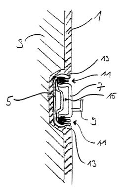
Figure 1 shows the cross-section through a mounting arrangement in the inner
fining or inner wall 1 of e.g. a refrigerator and/or freezer. On the outside
of the
inner wall 1, the foamed thermal insulation 3 is provided in a manner known
per
se. The receiving contour 15, which is formed in the plastic inner wall 1,
positively
incorporates the fixed part of the pull-out rail 5, which is shown here in
cross-
section. In the pull-out rail 5, which is retained by the positive connection
with e.g.
the beads 13, a movable pull-out rail 7 with a supporting device 9 far a pull-
out tray
or pull-out drawer is running via bearings known per se, e.g. ball bearings or
other
roller bearings 11.
CA 02561199 2006-09-22
- S -
The pull-out rail 5 substantially is mounted flush, so that cleaning the inner
waft 1
is easily possible. Due to the fact that the pull-out rail 5 is received in
the inner wall
1, the space available in the cooling chamber is enlarged and optically more
pleasing than in the case of mounting the pull-out rail on a planar inner
wall.
For producing the mounting arrangement of Figure 1, the plastic inner wall 1
is
shaped in a deep-drawing process such that it has the cross-sectional shape as
shown in Figure 1. Subsequently, the prefabricated pull-out rail 5 is clipped
from
the right-hand side of Figure 1 through the constrictions 13 into the flexible
inner
wall 1 having little stability. Then, the inner wall is processed in a manner
known
per se in the further production process of the refrigerator and/or freezer.
In
particular, by means of an outer wall not shown in Figure 1 and the inner wall
1 a
cavity is created, which is filled with foam 3 for thermal insulation. By
means of this
foaming process, the receiving contour 15 in the inner wall 1 is supported and
strengthened from outside, so that the pull-out rail 5 is retained.
In an alternative production process, the pull-out rail 5 is placed onto the
inner wall
lining 1 not yet deep-drawn, and during the deep-drawing process is used as a
mold for the receiving contour 15. In such a method, the pull-out rail is
already
retained in the inner wall fining 1 after the deep-drawing process and is then
strengthened and stabilized from the back of the inner wall 1 by the foaming
process for the foam 3, as described above.
The embodiment of Figure 2 shows a cross-section through a differently shaped
receiving contour 115, in which a number of snap-in cups 21 is formed along
the
direction vertical to the plane of the Figure. A pull-out rail 5 equipped with
corresponding latching noses 23 can be inserted into the receiving contour 115
in
the direction of the arrow and can be retained by the connection of latching
noses
23 and snap-in cups 21. Such aspect in particular provides for an easy
replacement of the pull-out rail 5, e.g. in the case of service.
In such an embodiment, it can alternatively be provided that a latching nose
23
extends along the pull-out rail 5, and the snap-in cup 21 extends like a
groove
vertical to the plane of the Figure.
CA 02561199 2006-09-22
-7-
The embodiments of Figures 1 and 2 can of course also be combined with each
other, so that a mounting arrangement is provided by a positive retention of a
pull-
out rail 5 enclosed by an inner wall lining 1 with an additional fixation by
latching
noses 23 in snap-in cups 21.