Note: Descriptions are shown in the official language in which they were submitted.
CA 02561242 2006-09-28
SURGICAL STAPLING INSTRUMENT HAVING PRELOADED
FIRING ASSISTANCE MECHANISM
Field of the Invention
loom The present invention relates in general to surgical stapler instruments
that are capable
of applying lines of staples to tissue while cutting the tissue between those
staple lines
and, more particularly, to improvements relating to stapler instruments and
improvements
in processes for forming various components of such stapler instruments.
Background of the Invention
100021 Endoscopic and laparoscopic surgical instruments are often preferred
over traditional
open surgical devices since a smaller incision tends to reduce the post-
operative recovery
time and complications. The use of laparoscopic and endoscopic surgical
procedures has
been relatively popular and has provided additional incentive to develop the
procedures
further. In laparoscopic procedures, surgery is performed in the interior of
the abdomen
through a small incision. Similarly, in endoscopic procedures, surgery is
performed in any
hollow viscus of the body through narrow endoscopic tubes inserted through
small
entrance wounds in the skin.
100031 Laparoscopic and endoscopic procedures generally require that the
surgical region be
insufflated. Accordingly, any instrumentation inserted into the body must be
sealed to
ensure that gases do not enter or exit the body through the incision.
Moreover,
laparoscopic and endoscopic procedures often require the surgeon to act on
organs,
tissues and/or vessels far removed from the incision. Thus, instruments used
in such
procedures are typically long and narrow while being functionally controllable
from a
proximal end of the instrument.
100041 Significant development has gone into a range of endoscopic surgical
instruments that
are suitable for precise placement of a distal end effector at a desired
surgical site through
a cannula of a trocar. These distal end effectors engage the tissue in a
number of ways to
achieve a diagnostic or therapeutic effect (e.g., endocutter, grasper, cutter,
staplers, clip
- 1 -
CA 02561242 2013-12-13
applier, access device, drug/gene therapy delivery device, and energy device
using
ultrasound, RF, laser, etc.).
100051 Known surgical staplers include an end effector that simultaneously
makes a
longitudinal incision in tissue and applies lines of staples on opposing sides
of the incision.
The end effector includes a pair of cooperating jaw members that, if the
instrument is
intended for endoscopic or laparoscopic applications, are capable of passing
through a
cannula passageway. One of the jaw members receives a staple cartridge having
at least two
laterally spaced rows of staples. The other jaw member defines an anvil having
staple-
forming pockets aligned with the rows of staples in the cartridge. The
instrument includes a
plurality of reciprocating wedges which, when driven distally, pass through
openings in the
staple cartridge and engage drivers supporting the staples to effect the
firing of the staples
toward the anvil.
[00061 An example of a surgical stapler suitable for endoscopic applications
is described in
U.S. Pat. Appl. Pub. No. US 2004/0232196 Al, the disclosure of which is hereby
incorporated by reference in its entirety. The disclosed surgical stapling and
severing
instrument enables a clinician to close the jaw members upon tissue to
position the tissue
prior to firing. Once the clinician has determined that the jaw members are
properly
gripping tissue, the clinician can then fire the surgical stapler to sever and
staple the tissue.
The simultaneous severing and stapling avoids complications that may arise
when
performing such actions sequentially with different surgical tools that
respectively only
sever or staple. In addition, a retraction spring assists in retracting firing
components so that
the jaws may be unclamped to release the stapled and severed tissue portions.
100071 Thus, while such surgical staplers have provided a significant
advancement in surgical
procedures, further features would be desirable, such as reducing the force to
fire. The
requirement of a higher force to operate the trigger may be inconvenient or
difficult for a
surgeon with limited hand strength. One successful approach to lowering the
force to fire is
utilizing multiple firing strokes, as described in U.S. Pat. Appin. Ser. No.
11/052,632,
entitled "MULTI-STROKE MECHANISM WITH AUTOMATED END OF STROKE
RETRACTION", to Swayze et al., filed 07 February 2005. However, it may be
desirable in
some
2
CA 02561242 2006-09-28
instances to retain the simplicity of a single firing stroke, or to reduce
force to fire during
each stroke of multiple firing strokes.
i00081 Consequently, a significant need exists for an improved surgical
stapling and severing
instrument that effectively severs and staples tissue, but with a reduced
amount of force
required to pull a firing trigger to cause the severing and stapling.
Brief Summary of the Invention
100091 The invention overcomes the above-noted and other deficiencies of the
prior art by
providing a surgical instrument that performs a surgical procedure by firing a
firing
member through an elongate implement portion. This firing motion occurs by the
action
of a firing actuator moved by the surgeon. The surgeon is assisted by
preloading an
assistance mechanism in a handle of the surgical instrument, perhaps by a
surgical nurse
during the preparation of the surgical procedure. This preloaded bias, which
is either
toward firing or toward retraction, is coupled to the firing member when the
firing
member is to move in a tiring direction or a retracting direction,
respectively.
loom] In one aspect of the invention, a surgical instrument has an assistance
mechanism with
a follower member proximate and aligned for movement between an unfired and
fired
positions of a proximal portion of a firing drive train in a handle. A biasing
member urges
the follower member in a selected direction between unfired and fired
positions after
being preloaded by the movement of the shuttle in the opposite direction. An
engagement
mechanism releases the follower member, which is preloaded by the biasing
member and
engaged to the proximal portion of the firing mechanism. The release is in
response to
the proximal portion of the firing mechanism being moved in the selected
direction.
100111 In another aspect of the invention, a surgical instrument includes a
proximal portion
of a firing mechanism that is held in place by a brake of an engagement
mechanism when
a follower member is moved from a fired position to an unfired position, which
preloads a
biasing member in the opposite direction, and engages the biased follower
member to the
firing mechanism. Firing of the firing mechanism releases the brake to enable
assisted
firing. Thereby, an effective firing of the implement portion is achieved even
if high
3
CA 02561242 2006-09-28
firing forces are required and the surgeon has limited strength to move the
firing
mechanism to achieve the required firing forces.
100121 In yet another aspect of the invention, a surgical instrument
incorporates preloading of
a retraction assistance mechanism that is disengaged during firing to reduce
opposition to
firing, yet readily engages after firing to retract the firing member through
the elongate
implement portion.
100131 These and other objects and advantages of the present invention shall
be made
apparent from the accompanying drawings and the description thereof.
Brief Description of the Figures
100141 The accompanying drawings, which are incorporated in and constitute a
part of this
specification, illustrate embodiments of the invention, and, together with the
general
description of the invention given above, and the detailed description of the
embodiments
given below, serve to explain the principles of the present invention.
100151 FIGURE 1 depicts a right side view in elevation of a surgical
stapling and severing
instrument in an open position with an open end effector (staple applying
assembly),
partially cut away elongate shaft and a firing assistance mechanism.
100161 FIGURE 2 depicts a right side view of the open end effector taken in
longitudinal
cross-section along the lines 2-2 of FIG. 1 of the surgical stapling and
severing
instrument.
100171 FIGURE 3 is a front left isometric view of the surgical stapling and
severing
instrument of FIG. 1 with a staple cartridge removed.
100181 FIGURE 4 is a left isometric view of a handle of the surgical
stapling and severing
instrument of FIG. 1 with a left handle housing shell and firing trigger
retraction spring
removed to expose a tension-spring firing assistance mechanism in a retracted
(preloaded)
state.
100191 FIGURE 5 is a front left isometric view of a disassembled surgical
stapling and
severing instrument of FIG. 1 with the end effector omitted.
4
CA 02561242 2006-09-28
100201 FIGURE 6 depicts a left side elevational view of the handle portion
of the surgical
stapling and severing instrument of FIG. 1 with a left handle housing shell
and assistance
mechanism removed to expose interior closure and firing components in an
unclamped,
unfired ("start") position.
100211 FIGURE 7 depicts a left side elevational view of the handle of the
surgical stapling
and severing instrument of FIG. 7 with the left handle housing shell and
assistance
mechanism removed to expose interior closure and firing components in a
"clamped"
position.
100221 FIGURE 8 depicts a left side elevational view of the handle of the
surgical stapling
and severing instrument of FIG. 8 with the left handle housing shell and
assistance
mechanism removed to expose interior closure and firing components in the
stapled and
severed ("fired") position.
100231 FIGURE 9 depicts an isometric view of the end effector at the distal
end of the
surgical stapling and severing instrument of FIG. 1 with the anvil in the up
or open
position exposing the staple cartridge and cutting edge of a firing bar.
100241 FIGURE 10 depicts an isometric, exploded view of the implement portion
of the
surgical stapling and severing instrument of FIG. 1.
100251 FIGURE 11 depicts an isometric view of the end effector at the
distal end of the
surgical stapling and severing instrument of FIG. 1 with the anvil in the up
or open
position with the staple cartridge largely removed exposing a single staple
driver and a
double staple driver as exemplary and a wedge sled in a start position against
a middle pin
of the firing bar.
100261 FIG 12 depicts an isometric view of the distal end of the surgical
stapling and
severing instrument of FIG. 1 with the anvil in the up or open position with
the staple
cartridge completely removed and a portion of an elongate channel removed to
expose a
lowermost pin of the firing bar.
100271 FIGURE 13 depicts a side elevation view in section showing a
mechanical
relationship between the anvil, elongate channel, and staple cartridge in the
closed
CA 02561242 2006-09-28
position of the surgical stapling and severing instrument of FIG. 1, the
section generally
taken along lines 13-13 of FIG. 9 to expose the wedge sled, staple drivers and
staples but
also depicting the firing bar along the longitudinal centerline.
[00281 FIGURE 14 depicts a section view of the end effector of the surgical
stapling and
severing instrument with the cartridge and firing bar in the start position
taken along line
14-14 of FIG. 9.
100291 FIGURE 15 depicts a section view taken along line 15-15 of Fig. 14
showing the
cross-sectional relationship between the firing bar, elongate channel, wedge
sled, staple
drivers, staples and staple cartridge.
[0030] FIGURE 16 is a top view of the tension spring firing assistance
mechanism of FIG. 4
in an initial, start state with a small rack (rectangular plate of a firing
drive train) retracted
and an unloaded shuttle.
100311 FIGURE 17 is a top view of the tension spring firing assistance
mechanism of FIG. 16
in an armed state (preloaded) with the small rack retracted by the shuttle
causing an
extended tension spring.
100321 FIGURE 18 is a top view of the tension spring firing assistance
mechanism of FIG. 17
in a triggered state (firing) with the small rack being distally biased by the
extended
tension spring via the engaged shuttle while being simultaneously distally
advanced by a
firing trigger.
100331 FIGURE 19 is a top view of the tension spring firing assistance
mechanism of FIG. 18
in a unloaded, fired state with the small rack being proximally retracted to
return to the
initial state after disengagement from the distally-positioned shuttle.
100341 FIGURE 20 is a left side view in elevation of a top aft portion of
the handle with the
left handle housing shell removed from the surgical stapling and severing
instrument of
FIG. I exposing a firing handle being fired to release a small rack brake of
the firing
assistance mechanism of FIG. 4.
6
CA 02561242 2006-09-28
100351 FIGURE 21 is a front left isometric view of the small rack and brake
assembly of
FIG. 20.
100361 FIGURE 22 is a left side view in elevation of a top aft portion of a
right handle
housing shell having a laterally elongate firing axle slot and an axle bias
leaf spring of the
firing assistance mechanism of FIG. 4.
100371 FIGURE 23 is a left side detail view of the laterally elongate
firing axle slot of the
right handle housing shell of FIG. 22.
100381 FIGURE 24 is a diagrammatic aft view in vertical cross section of the
small rack and
brake assembly of the firing assistance mechanism of FIG. 4.
100391 FIGURE 25 is a left side detail view of a portion of the small rack,
brake pad and
brake linkages of the firing assistance mechanism of FIG. 4.
100401 FIGURE 26 is a left side detail view of the small rack and the small
rack brake of
FIG. 24 in a locked state.
100411 FIGURE 27 is a left side detail view of the small rack and the small
rack brake of
FIG. 27 moved to an unlocked state.
100421 FIGURE 28 is a left side view in elevation of a top aft portion of the
handle with the
left handle housing shell removed from the surgical stapling and severing
instrument of
FIG. 1 exposing a firing handle being fired to release an alternative small
rack brake for
the firing assistance mechanism of FIG. 4.
100431 FIGURE 29 is a left side detail view of the alternative small rack
brake of FIG. 28.
100441 FIGURE 30 is a top view of an alternative compression spring firing
assistance
mechanism in an initial, start state with a small rack retracted and an
unloaded shuttle for
the surgical stapling and severing instrument of FIG. 1.
100451 FIGURE 31 is a top view of the compression spring firing assistance
mechanism of
FIG. 30 in an armed state (preloaded) with the small rack retracted and
engaged to a
retracted shuttle with a compressed compression spring.
7
CA 02561242 2006-09-28
100461 FIGURE 32 is a top view of the tension spring firing assistance
mechanism of FIG. 31
in a triggered state (firing) with the small rack being distally biased by the
compression
spring via the engaged shuttle while simultaneously being distally advanced by
the firing
trigger.
100471 FIGURE 33 is a top view of the tension spring firing assistance
mechanism of FIG. 32
in a retraction state after firing with the small rack being proximally
retracted (shown in
phantom) to return to the initial state after disengagement from the distally-
positioned
plunger.
100481 FIGURE 34 is a front right perspective view of a handle of a surgical
stapling and
severing instrument with a wind-up firing assistance mechanism.
100491 FIGURE 35 is a bottom view of the handle of the surgical stapling and
severing
instrument of FIG. 34 with a left handle housing shell omitted and a bottom
portion of a
right handle housing shell cut away to expose the wind-up firing assistance
mechanism.
100501 FIGURE 36 is a bottom detail view of the wind up firing assistance
mechanism of
FIG. 35.
[00511 FIGURE 37 is a front left isometric view of a winding knob, portion
of housing,
ratchet gear and an assisted spur gear of the wind up firing assistance
mechanism of FIG.
34.
100521 FIGURE 38 is a front left isometric view of the winding knob, ratchet
gear and an
assisted spur gear multiplier gear of FIG. 37 with a small outer spur gear
removed to
expose a torsion coil spring of the ratchet gear.
100531 FIGURE 39 is a side view of the torsion coil spring of FIG. 38 in a
relaxed, loose coil.
100541 FIGURE 40 is a side view of the torsion coil spring of FIG. 39 in an
actuated, tight
coil.
100551 FIGURE 41 is a front left perspective view of a handle of a surgical
stapling and
severing instrument including a retraction disengagement firing assistance
mechanism.
8
CA 02561242 2006-09-28
loo561 FIGURE 42 is a front left isometric detail view of a small rack and
shuttle of the
retraction disengagement firing assistance mechanism of FIG. 41.
100571 FIGURE 43 is a top view of the retraction disengagement firing
assistance mechanism
of FIG. 41 in an initial state, start state with a small rack and shuttle
retracted.
100581 FIGURE 44 is a top view of the retraction disengagement firing
assistance mechanism
of FIG. 43 being armed by distally advancing the shuttle with the small rack
remaining
retracted.
100591 FIGURE 45 is a top view of the retraction disengagement firing
assistance mechanism
of FIG. 44 being armed by further distally advancing the shuttle with the
small rack
remaining retracted.
100601 FIGURE 46 is a top view of the retraction disengagement firing
assistance mechanism
of FIG. 45 armed (pre-loaded) by a dual locking cam assembly being pivoted
within the
shuttle into engagement with the handle housing while the small rack remains
retracted.
100611 FIGURE 47 is a top view of the retraction disengagement firing
assistance mechanism
of FIG. 46 remaining armed (pre-loaded) as the small rack distally advances
during firing
of the surgical stapling and severing instrument.
100621 FIGURE 48 is a top view of the retraction disengagement firing
assistance mechanism
of FIG. 47 with the small rack distally advanced to approximately full travel
into contact
with the dual locking cam assembly to effect disengagement from the handle
housing.
100631 FIGURE 49 is a top view of the retraction disengagement firing
assistance mechanism
of FIG. 48 with the small rack fully distally advanced to rotate the dual
locking cam
assembly fully out of engagement with the handle housing and into engagement
with the
small rack.
100641 FIGURE 50 is a top view of the retraction disengagement firing
assistance mechanism
of FIG. 49 with the small rack retracting under the retraction bias from the
shuttle.
100651 FIGURE 51 is an isometric view of the dual locking cam assembly of FIG.
43.
9
CA 02561242 2006-09-28
100661 FIGURE 52 is an isometric disassembled view of the dual locking cam
assembly of
FIG. 44.
Detailed Description of the Invention
100671 Turning to the Drawings, wherein like numerals denote like components
throughout
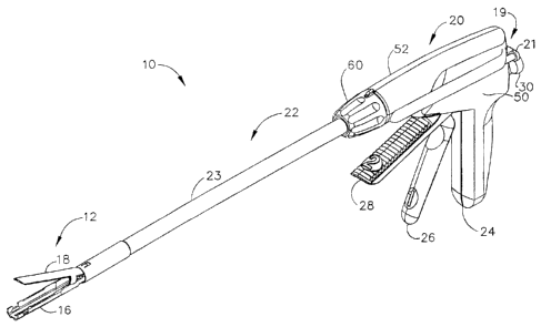
the several views, in FIG. 1, a surgical stapling and severing instrument 10
is depicted
that is capable of practicing the unique benefits of the present invention.
The surgical
stapling and severing instrument 10 incorporates an end effector 12, which in
the
illustrative version is a staple applying assembly having an E-beam firing
member
("firing bar") 14 (FIG. 2) that controls the spacing of the end effector 12.
In particular, an
elongate channel 16 and a pivotally translatable anvil 18 are maintained at a
spacing that
assures effective stapling and severing. Firing this firing bar 14 requires an
amount of
force to sever tissue, form staples, and to overcome mechanical resistance in
the surgical
stapling and severing instrument 10. Consistent with aspects of the present
invention, an
assistance mechanism 19 is incorporated into a handle portion 20 to reduce the
amount of
force necessarily imparted by the surgeon at the time of firing to achieve
this amount of
firing force imparted to the firing bar 14. A preloading actuator, depicted as
a firing
assistance plunger 21 accessible on a left, aft surface of the handle portion
20, allows a
surgeon or surgical nurse to prepare the surgical stapling and severing
instrument 10 by
preloading an amount of mechanical potential energy that subsequently assists
in firing.
00681 It will be appreciated that the terms "proximal" and -distal" are used
herein with
reference to a clinician gripping the handle portion 20 of the surgical
stapling instrument
10. Thus, the end effector 12 is distal with respect to the more proximal
handle portion
20. The end effector 12 is viewed from the front and the handle portion 20 is
viewed from
aft. It will be further appreciated that for convenience and clarity, spatial
terms such as
-vertical" and -horizontal- are used herein with respect to the drawings.
However,
surgical instruments are used in many orientations and positions, and these
terms are not
intended to be limiting and absolute.
100691 The surgical and stapling and severing instrument 10 includes an
implement portion
22 comprising a shaft 23 proximally attached to the handle portion 20 and
distally
CA 02561242 2006-09-28
terminating in the end effector 12. The handle portion 20 includes a pistol
grip 24 toward
which a closure trigger 26 is pivotally drawn by the clinician to cause
clamping, or
closing, of the anvil 18 toward the elongate channel 16 of the end effector
12. A firing
trigger 28 is farther outboard of the closure trigger 26 and is pivotally
drawn by the
clinician to cause the stapling and severing of clamped tissue in the end
effector 12.
100701 In preparation for use, a surgical nurse may draw the firing
assistance plunger 21
proximally (aft) until locked into place (FIG. 4). An adjustment knob 29 (FIG.
1) on a
right side of the handle portion 20 may be turned to vary that amount of
initial force
required on the firing trigger 28 to activate the assistance mechanism 19. A
desired type
of staple cartridge 37 would also be inserted into the end effector 12. The
surgeon then
depresses the closure trigger 26 to close the end effector 12 and then may
position the
implement portion 22 through a cannula of a trocar (not shown) to a desired
surgical site
within the patient's body. Closure trigger 26 is actuated first. Once the
clinician is
satisfied with the positioning of the end effector 12, the clinician may draw
back the
closure trigger 26 to its fully closed, clamped position proximate to the
pistol grip 24.
Then, the firing trigger 28 is actuated. The firing trigger 28 springedly
returns when the
clinician removes pressure. A release button 30, when depressed on the
proximal end of
the handle portion 20, releases the clampled closure trigger 26.
100711 The closure motion and firing motion are transferred down the elongate
shaft 23. In
particular, a closure sleeve 32 encloses a frame 34, which in turn encloses a
firing drive
rod 36 that is positioned by the firing trigger 28. The frame 34 connects the
handle
portion 20 to the end effector 12. With the closure sleeve 32 withdrawn
proximally by the
closure trigger 26 as depicted, the anvil 18 springedly opens, pivoting away
from the
elongate channel 16 and translating proximally with the closure sleeve 32. The
elongate
channel 16 receives a staple cartridge 37.
100721 In FIG. 2, the tiring bar 14 includes three vertically spaced pins
that control the
spacing of the end effector 12 during firing. In particular, an upper pin 38
is staged to
enter an anvil pocket 40 near the pivot between the anvil 18 and elongate
channel 16.
When fired with the anvil 18 closed (FIG. 13), the upper pin 38 advances
distally within a
longitudinal anvil slot 42 extending distally through anvil 18. Any minor
upward
11
CA 02561242 2006-09-28
deflection in the anvil 18 is overcome by a downward force imparted by the
upper pin 38.
Similarly, if insufficient tissue is clamped, the upper pin 38 may hold up the
anvil 18 for
proper staple formation. Firing bar 14 also includes a lower most pin, or
firing bar cap, 44
that upwardly engages a channel slot 45 in the elongate channel 16, thereby
cooperating
with the upper pin 38 to draw the anvil 18 and the elongate channel 16
slightly closer
together in the event of excess tissue clamped there between or to space part
in the event
of insufficient tissue. The firing bar 14 includes a middle pin 46 that passes
through a
firing drive slot 47 formed in a lower surface of the cartridge 37 proximate
to an upward
surface of the elongate channel 16, thereby driving the staples therein as
described below.
The middle pin 46, by sliding against a lower surface of the staple cartridge
37 that rests
upon the elongate channel 16, resists any tendency for the end effector 12 to
be pinched
shut at its distal end. A distally presented cutting edge 48 between the upper
and middle
pins 38, 46 on the firing bar 14 traverses through a proximally presented,
vertical slot 49
in the staple cartridge 37 to sever clamped tissue. The affirmative
positioning of the firing
bar 14 with regard to the elongate channel 16 and anvil 18 assure that an
effective cut is
performed.
too731 In FIG. 4, the handle portion 20 is partially disassembled from the
depiction of FIG. 3
to expose the assistance mechanism 19 that is integrated onto a left side of
internal
components of the handle portion 20, the latter as described in the U.S. Pat.
Appl. Pub.
No. US 2004/0232196 Al cross referenced above. In FIG. 5, the handle portion
20 is
fully disassembled. In particular, the handle portion 20 is comprised of left
and right
handle housing shells 50 and 52, which are molded from a polymeric material
such as a
glass-filled polycarbonate. The left handle housing shell 50 is provided with
a plurality of
cylindrical-shaped pins 54. The right handle housing shell 52 includes a
plurality of
extending members 56, each having a hexagonal-shaped opening 58. The
cylindrical-
shaped pins 54 are received within the hexagonal-shaped openings 58 and are
frictionally
held therein for maintaining the left and right handle housing shells 50, 52
in assembly.
100741 With particular reference to FIG. 5, a rotating knob 60 has a bore
62 extending
completely through it for engaging and rotating the implement portion 22 about
its
longitudinal axis. The rotating knob 60 includes an inwardly protruding boss
64
12
CA 02561242 2006-09-28
extending along at least a portion of the bore 62. The protruding boss 64 is
received
within a longitudinal slot 66 formed at a proximal portion of the closure
sleeve 32 such
that rotation of the rotating knob 60 effects rotation of the closure sleeve
32. It will be
appreciated that the boss 64 further extends into a proximal slot 67 in the
frame 34 to
effect rotation of the elongate shaft 23. Thus, the end effector 12 (FIGS. 1-
3) rotates with
the rotating knob 60.
100751 A proximal end 68 of the frame 34 passes proximally through the
rotating knob 60
and is provided with a circumferential notch 70 that is engaged by opposing
channel
securement members 72 extending respectively from the left and right handle
housing
shells 50, 52. Only the channel securement member 72 of the right handle
housing shell
52 is shown. The channel securement members 72 extending from the left and
right
handle housing shells 50, 52 serve to secure the frame 34 to the handle
portion 20 such
that the frame 34 does not move longitudinally relative to the handle portion
20, but is
allowed to rotate about its longitudinal axis.
100761 The closure trigger 26 has a handle section 74, a gear segment section
76, and an
intermediate section 78. A bore 80 extends through the intermediate section
78. A
cylindrical support member 82 extending from the right handle housing shell 52
passes
through the bore 80 for pivotably mounting the closure trigger 26 on the
handle portion
20.
100771 In the afore-referenced U.S. Pat. Appl. Pub. No. US 2004/0232196 Al,
the firing
trigger 28 was pivotally supported upon a second, smaller cylindrical support
member
that coaxially extends to the left and passes through a bore 81 of firing
trigger 28 and into
engagement with the left handle housing shell 50 of the handle portion 20 (not
shown).
Instead, the assistance mechanism 19 advantageously includes a longitudinally
movable
firing trigger axle 83 that passes though the bore 81 of the firing trigger 28
and its lateral
ends slide within longitudinally elongate oval guides 84 formed into both the
left and
right handle housing shells 50, 52.
100781 A closure yoke 86 is housed within the handle portion 20 for
reciprocating movement
therein and serves to transfer motion from the closure trigger 26 to the
closure sleeve 32.
13
CA 02561242 2006-09-28
Support members 88, extending from the right handle housing shell 52 and
securement
member 72, which extends through a recess 89 in the yoke 86, support the yoke
86 within
the handle portion 20.
100791 A proximal end 90 of the closure sleeve 32 is provided with a flange 92
that is snap-
fitted into a receiving recess 94 formed in a distal end 96 of the yoke 86. A
proximal end
98 of the yoke 86 has a gear rack 100 that is engaged by the gear segment
section 76 of
the closure trigger 26. When the closure trigger 26 is moved toward the pistol
grip 24 of
the handle portion 20, the yoke 86 and, hence, the closure sleeve 32 move
distally,
compressing a spring 102 positioned between a distal narrowed ring 103 defined
in the
left and right handle housing shells 50, 52 and the distal end 96 of the
closure yoke 86,
that biases the yoke 86 proximally. Distal movement of the closure sleeve 32
effects
pivotal translation movement of the anvil 18 distally and toward the elongate
channel 16
of the end effector 12 and proximal movement effects closing, as discussed
below.
loosoi The closure trigger 26 is forward biased to an open position by a front
surface 130
interacting with an engaging surface 128 of the firing trigger 28. Clamp first
hook 104
that pivots top to rear in the handle portion 20 about a pin 106 restrains
movement of the
firing trigger 28 toward the pistol grip 24 until the closure trigger 26 is
clamped to its
closed position. I look 104 restrains firing trigger 28 motion by engaging a
lockout pin
107 in firing trigger 28. The hook 104 is also in contact with the closure
trigger 26. In
particular, a forward projection 108 of the hook 104 engages a member 110 on
the
intermediate section 78 of the closure trigger 26, the member 110 being
outward of the
bore 80 toward the handle section 74. Hook 104 is biased toward contact with
member
110 of the closure trigger 26 and engagement with lockout pin 107 in firing
trigger 28 by
a release spring 112. As the closure trigger 26 is depressed, the hook 104 is
moved top to
rear, compressing the release spring 112 that is captured between a rearward
projection
114 on the hook 104 and a forward projection 116 on the release button 30.
loom] As the yoke 86 moves distally in response to proximal movement of the
closure
trigger 26, an upper latch arm 118 of the release button 30 moves along a
proximal, upper
surface 120 on the yoke 86 until dropping into an upwardly presented recess
122 in a
proximal, lower portion of the yoke 86. The release spring 112 urges the
release button 30
14
CA 02561242 2006-09-28
outward, which pivots the upper latch arm 118 downwardly into engagement with
the
upwardly presented recess 122, thereby locking the closure trigger 26 in a
tissue clamping
position, such as depicted in FIG. 7.
100821 Returning to FIG. 5, the latch arm 118 can be moved out of the
recess 122 to release
the anvil 18 by pushing the release button 30 inward. Specifically, the upper
latch arm
118 pivots upward about pin 123 of the right handle housing shell 52. The yoke
86 is then
permitted to move proximally in response to return movement of the closure
trigger 26.
100831 A firing trigger return spring 124 is located within the handle
portion 20 with one end
attached to pin 106 of the right handle housing shell 52 and the other end
attached to a pin
126 on the firing trigger 28. The firing return spring 124 applies a return
force to the pin
126 for biasing the firing trigger 28 in a direction away from the pistol grip
24 of the
handle portion 20. The closure trigger 26 is also biased away from pistol grip
24 by
engaging surface 128 of firing trigger 28 biasing front surface 130 of closure
trigger 26.
100841 As the closure trigger 26 is moved toward the pistol grip 24, its
front surface 130
engages with the engaging surface 128 on the tiring trigger 28 causing the
firing trigger
28 to move to its "firing" position. When in its tiring position, the firing
trigger 28 is
located at an angle of approximately 45 to the pistol grip 24. After staple
firing, the
spring 124 causes the firing trigger 28 to return to its initial position.
During the return
movement of the firing trigger 28, its engaging surface 128 pushes against the
front
surface 130 of the closure trigger 26 causing the closure trigger 26 to return
to its initial
position. A stop member 132 extends from the right handle housing shell 52 to
prevent
the closure trigger 26 from rotating beyond its initial position.
100851 The surgical stapling and severing instrument 10 additionally
includes a firing
reciprocating assembly (-firing drive train") 134 that transfers firing
motions from the
firing trigger 28 to the end effector 12 for severing and stapling tissue.
Although a
separate closure approach is incorporated in the illustrative version,
applications
consistent with the present invention may use a first portion of the distal
travel of the
firing drive train 134 to close the end effector 12 with the later portions of
the distal travel
used to sever and staple. A proximal portion of the firing drive train 134 is
received
CA 02561242 2006-09-28
within the handle portion 20 and a distal portion of the firing drive train
134 is received
within the implement portion 22. The proximal portion of the firing drive
train 134 begins
with a longitudinally elongate rectangular plate 135 having a proximal gear
rack segment
136 that engaged to a gear segment 137 upwardly presented on the firing
trigger 28 above
the pivot axis defined by the bore 81 and Firing trigger axle 83. A distal
gear rack segment
138 on the rectangular plate 135 engages a leftward small spur gear (pinion)
139 of a
coaxial dual spur gear (multiplier gear) 140, which freewheels on a laterally
aligned gear
axle 143 and whose large spur gear (large pinion) 141 engages a rod gear rack
142
formed on a proximal end of the firing drive rod 36. The firing rod 36 and
firing bar 14
thus form the distal portion of the firing drive train 134 that transfer this
firing motion
through the implement portion 22.
100861 A first notch 144 is provided on the rectangular plate 135 intermediate
the proximal
and distal gear rack segments 136, 138. During return movement of the firing
trigger 28, a
tooth 146 on the firing trigger 28 engages with the first notch 144 on the
rectangular plate
135 for returning the rectangular plate 135 to its initial position after
staple firing. A
second notch 148 is located at a proximal end of the firing drive rod 36 for
locking the
firing drive rod 36 to the upper latch arm 118 of the release button 30 in its
unfired
position.
min Before describing the components and operation of the assistance
mechanism 19, in
FIGS. 6-8, the handle portion 20 is depicted with the left handle housing
shell 50 and the
assistance mechanism 19 removed for clarity in describing the closure and
firing
components. In FIG. 6, the handle portion 20 is in the start position (open
and unfired). In
FIG. 7, the handle portion 20 is in a clamped position (closed and unfired).
In FIG. 8, the
handle portion is in a fired position. In order to prevent staple firing
before tissue
clamping has occurred, the upper latch arm 118 on the release button 30 is
engaged with
the second notch 148 on the rectangular plate 135 such that the firing drive
rod 36 is
locked in its proximal-most position, as depicted in FIG. 6. When the upper
latch arm 118
falls into the recess 122, the upper latch arm 118 disengages with the second
notch 148 to
permit distal movement of the firing drive rod 36, as depicted in FIG. 8.
16
CA 02561242 2006-09-28
100881 Because the distal gear rack segment 138 on the rectangular plate 135
and the rod
gear rack 142 on the firing drive rod 36 are engaged with the multiplier gear
140,
movement of the firing trigger 28 causes the firing drive rod 36 to
reciprocate between a
first reciprocating position, shown in FIG. 7, and a second reciprocating
position, shown
in FIG. 8. Since the diameter of the large pinion gear 141 is greater than the
diameter of
the small pinion gear 139, the multiplier gear 140 moves the distal portion of
the firing
drive train 134 (i.e., firing drive rod 36 and firing bar 14) a greater
distance than the
rectangular plate 135 is moved by the firing trigger 28. The relative
diameters of the
larger and small pinion gears 139, 141 may be selected to permit the length of
the stroke
of the firing trigger 28 and the force required to move it to be varied.
100891 The end effector 12 of the surgical stapling and severing instrument
10 is depicted in
further detail in FIGS. 9-15. As described above, the handle portion 20
produces separate
and distinct closing and firing motions that actuate the end effector 12. The
end effector
12 maintains the clinical flexibility of this separate and distinct closing
and firing (i.e.,
stapling and severing). In addition, the end effector 12 introduces the
aforementioned
ability to affirmatively maintain the closed spacing during firing after the
clinician
positions and clamps the tissue. Both features procedurally and structurally
enhance the
ability of the surgical stapling and severing instrument 10 by ensuring
adequate spacing
for instances where an otherwise inadequate amount of tissue is clamped and to
enhance
the clamping in instances where an otherwise excessive amount of tissue has
been
clamped.
100901 In FIG. 9, the end effector 12 is in an open position by a retracted
closure sleeve 32
and includes a staple cartridge 37 installed in the elongate channel 16. On a
lower surface
200 of the anvil 18, a plurality of stapling forming pockets 202 are arrayed
to correspond
to a plurality of stapler apertures 204 in an upper surface 206 of the staple
cartridge 37.
The firing bar 14 is at its proximal position, with the upper pin 38 aligned
in a
noninterfering fashion with the anvil pocket 40. The anvil pocket 40 is shown
as
communicating with the longitudinal anvil slot 42 in the anvil 18. The
distally presented
cutting edge 48 of the firing bar 14 is aligned with and proximally from
removed from the
vertical slot 49 in the staple cartridge 37, thereby allowing removal of a
spent cartridge
17
CA 02561242 2006-09-28
and insertion of an unfired cartridge, which is snapfit into the elongate
channel 16.
Specifically, extension features 208, 210 of the staple cartridge 37 engage
recesses 212,
214 (shown in FIG. 11) of the elongate channel 16.
100911 In FIG. 10, the implement portion 22 of the surgical stapling and
severing instrument
is in disassembled form. The staple cartridge 37 is shown as being comprised
of a
cartridge body 216, a wedge sled 218, single and double drivers 220, 221
staples 222
(FIGS. 13, 15), and a cartridge tray 224. When assembled, the cartridge tray
224 holds the
wedge sled 218, single and double drivers 220, 221 and staples 222 inside the
cartridge
body 216.
100921 Having a wedge sled 218 integral to the staple cartridge 37 enables a
number of
flexible design options as compared to incorporating camming surfaces onto a
firing bar
itself. For instance, a number of different staple cartridges 37 may be
selected for use in
the surgical stapling and severing instrument 10 with each staple cartridge 37
having a
different configuration of rows of staples 222, each thus having a unique
wedge sled 218
configured to contact the middle pin 46 of the firing bar 14 while causing the
driving of
the staples 222. As another example, the integral wedge sled 218 provides an
opportunity
for a number of lockout features.
[00931 The elongate channel 16 has a proximally placed attachment cavity 226
that receives
a channel anchoring member 228 on the distal end of the frame 34 for attaching
the end
effector 12 to the handle portion 20. The elongate channel 16 also has an
anvil cam slot
230 that pivotally receives an anvil pivot 232 of the anvil 18. The closure
sleeve 32 that
encompasses the frame 34 includes a distally presented horseshoe shaped
aperture 234
that engages an anvil feature 236 proximate but distal to the anvil pivot 232
on the anvil
18 to thereby effect opening and closing of the anvil 18. The firing drive rod
36 is shown
as being assembled to the firing bar 14 by a firing connector 238 by pins 240,
which in
turn is rotatingly and proximally attached to the firing drive rod 36. The
firing bar 14 is
guided at a distal end of the frame 34 by a slotted guide 239 inserted
therein.
100941 With particular reference to FIG. 11, a portion of the staple cartridge
37 is removed to
expose portions of the elongate channel 16, such as recesses 212, 214 and to
expose some
18
CA 02561242 2006-09-28
components of the staple cartridge 37 in their unfired position. In
particular, the cartridge
body 216 (shown in FIG. 10) has been removed. The wedge sled 218 is shown at
its
proximal, unfired position with a pusher block 242 alligned to contact the
middle pin 46
(hidden in FIG. 11) of the firing bar 14. The wedge sled 218 is in
longitudinal sliding
contact upon the cartridge tray 224 and includes wedges 228 that force upward
the single
and double drivers 220, 221 as the wedge sled 218 moves distally. Staples 222
(not
shown in FIG. II) resting upon the drivers 220, 221 are thus also forced
upward into
contact with the anvil forming pockets 202 on the anvil 18 to form closed
staples 222.
Also depicted is the channel slot 45 in the elongate channel 16 that is
aligned with the
vertical slot 49 in the staple cartridge 37.
100951 In FIG. 12, the end effector 12 of FIG. 11 is depicted with all of
the staple cartridge
37 removed to show the middle pin 46 of the firing bar 14 as well as portion
of the
elongate channel 16 removed adjacent to the channel slot 45 to expose the
firing bar cap
44. In addition, portions ofthe shaft 23 are removed to expose a proximal
portion of the
firing bar 14. Projecting downward from the anvil 18 near the pivot, a pair of
opposing
tissue stops 244 prevent tissue from being positioned too far up into the end
effector 12
during clamping.
100961 In FIG. 13, the end effector 12 is closed in a tissue clamping
position with the firing
bar 14 unfired. The upper pin 38 is in the anvil pocket 40, vertically aligned
with the anvil
slot 42 for distal longitudinal movement of the firing bar 14 during firing.
The middle pin
46 is positioned to push the wedge sled 218 distally so that wedge 228
sequentially
contacts and lifts double drivers 221 and the respective staples 222 into
forming contact
with staple forming pockets 202 in the lower surface 200 of the anvil 18.
100971 In FIG. 14, the upper surface 206 of the staple cartridge 37 is
depicted with the firing
bar 14 in its unfired, proximal position. The stapler apertures 204 are
arrayed on each side
of the vertical slot 49 in the staple cartridge 37.
loo9s1 In FIG. 15, the portion of the elongate channel 16 of the end
effector 12 near the pivot
has opposing ramp portions 246 to thereby cooperate with the tissue stops 244
of the
19
CA 02561242 2006-09-28
anvil 18 (FIG. 12) to prevent tissue from jamming the end effector 12. Also
depicted in
greater detail are the double drivers 221 and their relation to the staples
222.
100991 Returning to FIGS. 4-5, the assistance mechanism 19 complements the
operation of
the afore-described firing components of the handle portion 20 having a spring
biased
follower member, which in the illustrative version is a linearly moving
shuttle 300, that
selectively urges a proximal portion of the firing drive train 134, which in
the illustrative
version is the rectangular plate 135. The shuttle 300 has a lateral through
slot 302 in
which a cam finger 304 is centrally engaged for horizontal rotation by a
vertical pin 306
residing in a pin hole 308. A proximal end of the shuttle 300 is attached to
the firing
assistance plunger 21 whose cylindrical shaft 310 slides through a plunger
hole 312 (FIG.
4) formed in the left handle housing shell 50 (FIG. 5). A stop surface of the
plunger 21 is
provided by an increased diameter cylindrical finger grip 314 at an aft end of
the
cylindrical shaft 310. A distal end of the shuttle 300 is attached to a
proximal hook end
315 of a tension spring 316 residing with a distally open lateral slot 317 in
the shuttle 300
by a pin 318. A distal hook end 320 of the tension spring 316 is attached to a
distal
portion of the left handle housing shell 50 such that retraction of the
plunger 21, as in
FIG. 4, stretches the tension spring 316 storing mechanical potential energy
therein. A
shuttle tray structure 323 formed in the left handle housing shell 50 guides
the tension
spring 316 and shuttle 300 and limits the distal movement of the shuttle 300
(FIG. 4).
loom In FIGS. 16-19, interaction is depicted between the shuttle 300 of the
assistance
mechanism 19 and the rectangular plate 135 of the firing drive train 134. The
cam finger
304 is generally an elongate rectangular plate with tapered in long sides
presenting a front
right corner that rotates clockwise, when viewed from above into a
corresponding notch
322 about midway along a top left edge of the rectangular plate 135. Thus, the
cam finger
304 may engage the rectangular plate 135 if inserted into the notch 322 with
the shuttle
300 biased distally. In FIG. 16, tension spring firing assistance mechanism 19
of FIG. 4 in
an initial, start state with the rectangular plate 135 retracted and with the
plunger distally
positioned and disengaged. An aft left surface of the cam finger 304 rests
upon a kick-out
cam step 324 attached to an internal surface of the left handle housing shell
50. It should
be appreciated that a torsion coil spring and/or the lateral spacing around
the cam finger
CA 02561242 2006-09-28
304 may bias the front, right surface of the cam finger 304 into contact with
the
rectangular plate 135 unless rotated counterclockwise, when viewed from above,
by
contact with the kick-out cam step 324. In FIG. 17, the tension spring firing
assistance
mechanism 19 of FIG. 16 has been armed by retracting the plunger 21 to an
armed state
(preloaded). The cam finger 304 is engaged into the notch 322 of the
rectangular plate
135 and the tension spring 316 has been longitudinally stretched to store
mechanical
potential energy. In FIG. 18, the tension spring firing assistance mechanism
19 of FIG. 17
is being fired distally, the rectangular plate 135 being urged by the firing
trigger 28 (not
shown in FIGS. 16-19) and assisted by the spring-biased shuttle 300. The cam
finger 304
has approached its most distal position as a beveled proximal surface of the
kick-out cam
step 324 contacts the aft left surface of the cam finger 304. In FIG. 19,
tension spring
firing assistance mechanism 19 of FIG. 18 has reached its unloaded, fired
state with the
cam finger 304 rotated counterclockwise as viewed from above out of engagement
with
the notch 322 in the rectangular plate 135, allowing a retraction bias and/or
reverse
movement of the firing trigger to retract the rectangular plate 135 (as shown
in phantom).
mum In FIGS. 5 and 20-27, a selective engagement mechanism of the firing
assistance
mechanism 19 that couples a firing assistance force during tiring includes
both the
selective engagement of the shuttle 300 to the rectangular plate 135 but also
the selective
release of the combination of the rectangular plate 135 and the shuttle 300
from a held
proximal position relative to the handle portion 20. To that end, a small rack
brake
assembly 340 of the assistance mechanism 19 holds the rectangular plate 135,
and thus
the firing drive train 134, in a proximal position until firing commences. The
firing trigger
axle 83 passes through a distal end hole 342 of a horizontal brake link 344. A
proximal
abutment surface 346 of the horizontal brake link 344 is urged distally by a
distally
bowed leaf spring 348 having an upper looped end 350 engaged to a lateral
pivot pin 352
extending from the left handle housing shell 50. A lower end 354 of the
distally bowed
leaf spring 348 is adjustably positioned longitudinally between the left and
right handle
housing shells 50, 52 by a cylindrical cam 356 having an off-center lateral
through hole
358 that receives an adjustment axle 360 rotationally fixed by a pin 362 and
turned by the
adjustment knob 29. The cylindrical cam 356 is rightward biased from contact
with the
21
CA 02561242 2006-09-28
left handle housing shell 50 by a spring 363 (FIG. 5). A locking finger 364
passing
transversely through the adjustment axle 360 frictionally engages at both ends
a frictional
ring surface 366 (FIG. 22) formed on an inner surface of the right handle
housing shell 52
to hold the adjusted position. Adjustment allows the user to vary the amount
of spring
force distally biasing the firing trigger axle 83 via horizontal brake link
344.
1001021 A block-shaped brake pad 368 is moved into braking contact with a
proximal
undersurface of the rectangular plate 135 proximal to the proximal gear rack
segment 136
when the horizontal brake link 344 is at its forward position with the firing
trigger axle 83
at a distal end of the longitudinally elongate oval guides 84 laterally
aligned in each
handle housing shell 50, 52. The block-shaped brake pad 368 is moved out of
braking
contact with the proximal undersurface of the rectangular plate 135 when the
horizontal
brake link 344 is at its aft position with the firing trigger axle 83 moved
away from the
distal end of the longitudinally elongate oval guides 84. This aft movement
occurs when
the firing trigger 28 is depressed with some of the resistance reacted by the
firing drive
train 134 being transferred to the firing trigger axle 83 and ultimately into
the distally
bowed leaf spring 348.
1001031 Horizontal motion of the horizontal brake link 344 is converted to an
aft and up
rotational motion (when viewed from the left when engaging) at the brake pad
368 by an
assembly that rotates as a plane laterally aligned by left and right lateral
spacing pins 370,
372 that extend respectively into sliding contact with the left and right
handle housing
shells 50, 52. In particular, a lower rod-shaped axle 374 passes through a
proximal lateral
through hole 376 in the horizontal brake link 344 and through a lower
horizontal through
hole 378, 380 respectively in left and right upper brake arms 382, 384 that
flank the
horizontal brake link 344. The left and right lateral spacing pins 370, 372
extend
respectively outward from the left and right upper brake arms 382, 384 from
respective
left and right holes 386, 388 above the respective lower horizontal through
hole 378, 380.
An upper square axle 390 passes through left and right upper through holes
392, 394 in
the respective upper brake arms 382, 384 and a generally horizontally elongate
rectangular through hole 396 (FIGS. 26-27) in the block-shaped brake 368. Left
and right
rectangular prism ends (shoe) 398, 400 with a lateral square cross section are
attached to
22
CA 02561242 2006-09-28
the ends of the upper square axle 390 on the lateral outside respectively of
the left and
right upper brake arms 382, 384. Each cubic end 398, 400 is received within a
respective
rectangular boss 402, 404 (FIGS. 21-22, 24-27) formed on the inner surface
respectively
of the left and right handle housing shells 50, 52.
1001041 It should
be appreciated that the firing drive train 134 is generally held in a
retracted
position by the firing trigger return spring 124 rotating the firing trigger
28 clockwise,
when viewed from the left. When the small rack brake assembly 340 is in its
default,
engaged position, as depicted in FIGS. 20-21, 25-26, with the horizontal brake
link 344
forward and the upper brake arms 382, 384 top aft, the rectangular plate 135
is allowed to
retract, as depicted as occurring in FIG. 19. However, the brake pad 368
creates sufficient
frictional force to offset any tendency of the firing drive train 134 to be
distally advanced
solely under the influence of the assistance mechanism 19 that might otherwise
overcome
this retraction force. With particular reference to FIG. 25-26, the small rack
brake
assembly 340 is urged into the default, engaged position by the forward
movement of the
horizontal brake link 344. The left and right rectangular bosses 402, 404 are
canted such
that forward movement at the connection between the horizontal brake link 344
and upper
brake arms 382, 384 causes the left and right shoes 398, 400 to move and aft
and upward
in the respective left and right bosses 402, 404. The upper square axle 390
can slide
within the generally horizontal rectangular through hole 396 in the brake pad
368 to allow
for retraction of the rectangular plate 135 and thus the firing drive train
134. In particular,
the generally horizontal rectangular through hole 396 is slightly canted
upward at its
distal end. Thus frictional contact of the brake pad 368 to the under surface
of the
rectangular plate 135 during retraction slides the brake pad 368 proximally
with the upper
square axle 390 positioned in a slightly higher distal portion of the
generally horizontal
through hole 396, allowing a slight gap to occur between the surfaces (FIG.
27).
Conversely, a distal bias on the firing drive train 134, such as when the
assistance
mechanism 19 is preloaded and engaged to the firing drive train 134, causes a
slight
distal movement of the brake pad 368, moving the upper square axle 390 to a
slightly
lower proximal portion of the generally horizontal through hole 396 in the
brake pad 368,
urging the brake pad 368 upwardly into braking contact with the rectangular
plate 135.
23
CA 02561242 2006-09-28
1001051 In FIGS. 28-29, an alternate small rack braking assembly 440 includes
the adjustable
distally bowed leaf spring 348 that forward biases a horizontal brake link 442
and thus the
firing trigger axle 83 as described above. An upper brake arm 444, however, is
perpendicularly and rigidly attached at a midpoint of the horizontal brake
link 442 to
selectively rotate an inverted J-shaped brake arm 446. A resilient guide 448,
formed in the
left handle housing shell 52, positions a top portion 450 of the inverted J-
shaped brake
arm 446 so that a downwardly curved proximal end 452 is rotated downward into
binding
contact with a recessed top surface 454 formed in the proximal end of the
rectangular
plate 135. A distal downwardly hanging portion 456 of the inverted J-shaped
brake arm
446 may be rotated proximally by a proximally moving upper brake arm 442
causing the
downwardly curved proximal end 452 to lift off of the recessed top surface 454
allowing
the firing drive train 134 to fire.
1001001 In FIGS. 30-33, an alternative firing assistance mechanism 500
includes the shuttle
300 that engages the rectangular plate 135 of the firing drive train 134 as
previously
described but urged with a compression spring 502 between a raised distal ring
504
formed on the cylindrical portion 310 of the plunger 21 and the plunger hole
312. In Fig.
30, the rectangular plate 135 and firing driving train 134 are retracted with
the alternative
firing assistance mechanism 500 in a distal, fired position with the
compression spring
502 unloaded. In FIG. 31, the plunger 21 has been drawn aft, engaging the cam
finger 304
and thus the shuttle 300 to the rectangular plate 135 as the compression
spring 502 is
compressed, storing mechanical potential energy. In FIG. 32, the assistance
mechanism
500 has been triggered, the firing drive train 134 and shuttle 300 moving in
unison as the
cam finger 304 begins to contact the kick-out cam step 324. In FIG. 32, with
further distal
movement, the kick-out cam step 324 has rotated the cam finger 304
counterclockwise as
viewed from above out of engagement with the notch 322 in the rectangular
plate 135,
which would be followed by retraction of the firing drive train 134. The
alternative firing
assistance mechanism 500 may utilize either brake assembly 340, 440.
1001071 In FIGS. 34-40, another alternative wind-up firing assistance
mechanism 600
incorporated into the surgical stapling and severing instrument 10 includes a
wind-up
knob 602 that stores mechanical potential energy in a torsion coil spring 604
in a ratchet
24
CA 02561242 2006-09-28
gear 606 that is in gear engagement to a third spur gear 605 coaxially
attached to the right
side of the coaxial dual spur gear (multiplier gear) 140 (FIGS. 35, 36). A
shaft 608
connects to the wind-up knob 602, passes through the right handle housing
shell 52 and is
attached to a circular flange 610 that pivotally holds a downwardly biased
ratchet pawl
612 that engages a rotatingly received ratchet gear 614 with teeth angled such
that
counterclockwise rotation of the ratchet gear 614, when viewed from the right,
is
prevented, the torsion coil spring 604 has an outer end 616 that is engaged to
the ratchet
gear 614 and an inner end 618 that is engaged to the shaft 608. A spur gear
620 is
attached for rotation with the ratchet gear 614 and is in gear engagement with
the third
spur gear 605 added to the coaxial dual spur gear (multiplier gear) 140. The
third spur
gear 605 that is coaxially attached to the right side of the dual spur gear
140 that is in gear
engagement with the spur gear 620 of the ratchet gear 606 may be sized to
provide a
desired gear ratio between the assistance mechanism 500 and the firing drive
train 134.
The alternative firing assistance mechanism 600 may utilize either brake
assembly 340,
440.
wows] In FIGS. 41-52, in addition to or as an alternative of direct assistance
in moving a
firing drive train 134 in a surgical stapling and severing instrument 10,
firing assistance
may be incorporated by disengaging a retraction force on the firing drive
train 134 during
firing. Thereby, the surgeon is not required to exert as great a force on the
firing trigger
28 yet retains the advantages of automatic retraction of the firing drive
train 134 after
firing. To that end, an assistance mechanism 700 is incorporated into the
surgical stapling
and severing instrument 10 with a shuttle 702 that is proximate to a left side
and aligned
for movement with the rectangular plate 135 having a reversed notch 704 near a
distal
end along a top left surface thereof Rather than being connected directly to
the firing
trigger 28, a retraction tension spring 706 whose fixed end (not shown) is
attached in the
pistol grip 24 has a moving end 708 that is connected to a cable 710 that
turns on a pulley
712 and is attached to a proximal end of the shuttle 702. The pulley 712 is
aligned to the
longitudinal travel of the shuttle 702 and is more proximal than a most
proximal position
of the shuttle 702.
CA 02561242 2006-09-28
1001091 A lateral through slot 714 near a distal end of the shuttle 702
receives a horizontally
rotating dual engagement cam member 716 that selectively engages the left
handle
housing shell 50 or the firing drive train 134. With particular reference to
FIGS. 51-52,
the dual engagement cam member 716 has a leftward canted distal end 718 that
is distal
to a vertical pivot through hole 720 and left and right proximal fingers 722,
724 that are
proximal to the vertical pivot through hole 720. A cam axle 726 has a
cylindrical upper
portion 728 that allows rotation of the cam member 716 with a square lower
portion 730
that is fixedly received into the shuttle 702 below the lateral through slot
714. A torsion
coil spring 732 has an inner end 734 attached to the cylindrical upper portion
728, is
wrapped counterclockwise as viewed from above, and has an outer end 736
engaged to
the cam member 716 such that the cam member 736 is biased clockwise into
contact with
the rectangular plate 135 of the firing drive train 134.
1001101 With particular reference to FIG. 41, a bent leaf spring 738 (shown in
phantom) has a
first end 740 inserted into the closure trigger 26 and a second end 742
inserted into the
firing trigger 28 with a curved portion 744 there between biased to separate
the two
triggers 26, 28. The bent leaf spring 738 compensates to a lesser degree for
the
disengagement of the retraction tension spring 706 from the firing trigger 28
by keeping
the firing trigger 28 from sagging and interfering with use of the closure
trigger 26.
milli In FIGS. 41-42, the assistance mechanism 700 is preloaded in preparation
for use of
the surgical stapling and severing instrument 10 by distally sliding a
retraction assistance
slide grip 746 that rides longitudinally along an actuator horizontal slot 748
(FIG. 41)
formed in the left handle housing shell 50.
1001121 In FIGS. 43-50, a small, distal ramped notch 750 and a large, proximal
ramped notch
752 formed on an inner surface of the left handle housing shell 50 in
combination with
the aligned cam member 716 act as an engagement mechanism that selectively
engage the
shuttle 702 to the left handle housing shell 50, the rectangular plate 135 of
the firing drive
train 134, or to neither. In FIG. 43, the rectangular plate 135, and thus the
firing drive
train 134, are in a retracted, unfired position. The shuttle 702 is also
retracted in an initial
unloaded state. The cam member 716 is positioned to the right of the large,
proximal
ramped notch 752. The clockwise bias of the torsion coil spring 732 on the cam
member
26
CA 02561242 2006-09-28
716 tends to rotate the left proximal finger 722 into the large, proximal
ramped notch 752
and the right proximal finger 724 out of the reversed notch 704 in the
rectangular plate
135 to the extent allowed by the leftward canted distal end 718 as the shuttle
702 is
distally advanced in FIG. 44, preloading the retraction tension spring 706
(FIG. 41). In
FIG. 45, the cam member 716 rotates counterclockwise as the left proximal
finger 722
exits the large, proximal ramped notch 752 in preparation for engaging the
right handle
housing shell 50, which occurs as the shuttle 702 reaches full distal travel
in FIG. 46. The
shallow nature of the small, distal ramped notch 750 allows sufficient
clockwise rotation
of the cam member 716 such that the left proximal finger 722 is in the small,
distal
ramped notch 750, the right proximal finger 724 is approximately flush with a
right edge
of the shuttle 702, and the leftward canted distal end 718 of the cam member
716 extends
slightly into the space traversed by the rectangular plate 135 of the firing
drive train 134.
In FIG. 47, the rectangular plate 135 of the firing drive train 134 is
distally advancing as
the firing trigger 28 (FIG. 41) is depressed during firing. A distal left
corner of the
rectangular plate 135 is approaching the leftward canted distal end 718 of the
cam
member 716 as the reversed notch 704 moves along the right side of the right
proximal
finger 724 of the cam member 716. In FIG. 48, the rectangular plate 135,
contacting the
leftward canted distal end 718 of the cam member 716, progressively rotates
the cam
member 716 counterclockwise, thus drawing the left cam finger 722 of the cam
member
716 out of engagement with the small, distal ramped notch 750 in the left
handle housing
shell 50 and positions the right proximal finger 724 into the reversed notch
704 of the
rectangular plate 135. In FIG. 49, further distal advancement to nearly full
firing travel of
the rectangular plate 135 has disengaged the cam member 716 from the right
handle
housing shell 50 and engaged the cam member 716 to the rectangular plate 135
of the
firing drive train 134, thus coupling the extended retraction tension spring
706 (FIG. 41)
to create a retraction bias. In FIG. 50, as the firing trigger 28 (FIG. 41) is
released, the
retraction bias retracts the shuttle 702 and thus the rectangular plate 135
(via the engaged
cam member 716) back toward the initial state of FIG. 43.
1001131 While the present invention has been illustrated by description of
several
embodiments and while the illustrative embodiments have been described in
considerable
detail, it is not the intention of the applicant to restrict or in any way
limit the scope of the
27
CA 02561242 2006-09-28
appended claims to such detail. Additional advantages and modifications may
readily
appear to those skilled in the art.
1001141 For example, an assistance mechanism consistent with aspects of the
invention may
be coupled in other ways to the firing rod rather than interposing a
multiplier gear
between a primary rack that is attached to the firing rod and a small
secondary rack.
looms' As another example, a retraction assistance mechanism, consistent with
aspects of the
invention, may store biasing energy in a compression spring or torsion coil
spring or other
resilient member (e.g., charged gas cylinder) rather than a tension spring,
similar to the
versions that biased the firing assistance mechanism.
loo1161 As yet another example, while a surgical stapling and severing
instrument benefits
from pre-loaded assistance in firing and/or retraction, other surgical
instruments may
benefit from aspects consistent with the present invention, to include but are
not limited
to a linear stapler, a circular stapler, an anastomosis instrument, etc.
1001171 As yet an additional example, a surgical stapling and severing
instrument may benefit
from incorporating a dual firing and retraction assistance mechanism that
includes
preloading for both assistance during the firing stroke and during the
retraction of a firing
drive train.
toms] As yet a further example, while a single firing stroke has been
described for clarity, a
multiple firing stroke surgical instrument, such as described in the above-
referenced U.S.
Pat. Appin. Ser. No. 1 1/052,632, may benefit from aspects consistent with the
present
invention.
28