Note: Descriptions are shown in the official language in which they were submitted.
CA 02561379 2006-09-26
METHOD FOR SENDING LOCATION-BASED MESSAGES TO MOBILE
USERS
The present application is related to the following co-pending, commonly
assigned patent applications, which were filed concurrently herewith and
incorporated
by reference in their entirety:
U.S. Serial No. 10/818,077, entitled "Selectively Enabling Communications at
a User Interface Using a Profile," attorney docket TC00167, filed concurrently
herewith.
U.S. Serial No. 10/818,109, entitled "Method for Enabling Communications
Dependent on User Location, User-Specified Location, or Orientation," attorney
docket TC00168, filed concurrently herewith.
U.S. Serial No. 10/818,000, entitled "Methods for Displaying a Route
Traveled by Mobile Users in a Communication Network," attorney docket TC00170,
filed concurrently herewith.
U.S. Serial No. 10/818,267, entitled "Conversion of Calls from an Ad Hoc
Communication Network," attorney docket TC00172, filed concurrently herewith.
U.S. Serial No. 10/818,381, entitled "Method for Entering a Personalized
Communication Profile Into a Communication User Interface," attorney docket
TC00173, filed concurrently herewith.
U.S. Serial No. 10/818,079, entitled "Methods and Systems for Controlling
Communications in an Ad Hoc Communication Network," attorney docket TC00174,
filed concurrently herewith.
CA 02561379 2006-09-26
WO 2005/101868 PCT/US2005/009442
2
U.S. Serial No. 10/818,299, entitled "Methods for Controlling Processing of
Inputs to a Vehicle Wireless Communication Interface," attorney docket
TC00175,
filed concurrently herewith.
U.S. Serial No. 10/818,080, entitled "Methods for Controlling Processing of
Outputs to a Vehicle Wireless Communication Interface," attorney docket
TC00176,
filed concurrently herewith.
U.S. Serial No. 10/818,076, entitled "Programmable Foot Switch Useable in
a Communications User Interface in a Vehicle," attorney docket TC00177, filed
concurrently herewith.
FIELD OF THE INVENTION
This invention relates to systems and methods for sending and receiving
location-based messages in a communication network.
BACKGROUND OF THE INVENTION
Communication systems, and especially wireless communication systems,
are becoming more sophisticated, offering consumers improved functionality to
communicate with one another. Such increased functionality has been
particularly
useful in the automotive arena, and vehicles are now being equipped with
communication systems with improved audio (voice) wireless communication
capabilities. For example, On StarTM is a well-known communication system
currently employed in vehicles, and allows vehicle occupants to establish a
telephone
call with others (such as a service center) by activating a switch.
CA 02561379 2006-09-26
WO 2005/101868 PCT/US2005/009442
3
Existing vehicle-based communication systems, however, contemplate
immediate communication between the two parties, which may not always be
desirable. For example, an occupant in a first vehicle may wish to remind a
second
vehicle of something at a particular time and/or at a particular location
along the
second vehicle's route. For example, the first vehicle may wish to post a
reminder
message to the second vehicle to have the user "turn right here, at Autumnway
Drive,
and pull into the diner to meet me." It may also be desired for a first user
to leave a
similar location-based message for the second vehicle even when that first
user is not
in a vehicle or not mobile. For example, the first user may wish from his home
to
leave a similar message for the second vehicle, such as "turn into the grocery
store
here and bring home a bottle of milk on your way home from work." Such
messages
are thus only relevant to the second vehicle when they are at or near the
particular
locations, and furthermore may only have pertinence at a particular time or
day. Such
functionality is not presently enabled in vehicle-based or other communication
systems.
It is, therefore, desirable to provide an improved vehicle communication
system that includes the sending and receiving location-based messages. In
particular, it would thus be convenient for vehicle-based (or other)
communication
systems to allow messages to be left for a second user at a particular
location and
further at a particular time or date. This disclosure presents several
different means
for meeting these needs.
BRIEF DESCRIPTION OF THE DRAWINGS
FIG. 1 is a block diagram of a wireless vehicular communications system;
CA 02561379 2006-09-26
WO 2005/101868 PCT/US2005/009442
4
FIG. 2 is a block diagram of a control system for a vehicular wireless
communications system;
FIG. 3 is diagram illustrating a map showing two vehicles and a house in
communication with a system in which location-based messages can be posted and
received;
FIGS. 4a-4d are embodiments of a user interface for posting a location-based
message for a user of the communication system;
FIG. 5 is a block diagram of a further embodiment of a control system with the
addition of a video camera to allow the posting of video messages;
FIG. 6 is a diagram illustrating two vehicles in wireless communication and
the transmission and storage of a location-based message from one vehicle to
the
other;
FIG. 7 illustrates one embodiment of a display in a user interface for
reviewing a textually-based location-based message;
FIG. 8 illustrates one embodiment of a display in a user interface for
reviewing a location-based message superimposed on a map marked with the
location;
FIG. 9 illustrates one embodiment of a display in a user interface for
reviewing a plurality of location-based messages superimposed on a map marked
with
the locations;
FIG. 10 illustrates one embodiment of a display in a user interface for
reviewing a plurality of textually-based location-based messages;
FIG. 11 illustrates one embodiment of a display in a user interface for
reviewing a plurality of audio or video-based location-based messages; and
CA 02561379 2006-09-26
WO 2005/101868 PCT/US2005/009442
S
FIG. 12 illustrates one embodiment of a monitor in the computer for posting a
location-based message to a mobile user.
While the invention is susceptible to various modifications and alternative
forms, specific embodiments have been shown by way of example in the drawings
and will be described in detail herein. However, it should be understood that
the
invention is not intended to be limited to the particular forms disclosed.
Rather, the
invention is to cover all modifications, equivalents and alternatives falling
within the
spirit and scope of the invention as defined by the appended claims.
DETAILED DESCRIPTION
What is described is a system and method for sending and receiving location-
based messages in a communication network. The system allows messages to be
posted to specified users and to be associated with a particular location for
which the
message is pertinent. The messages can be left when a user passes a particular
location, or the user can specify the location for the message even if not
present at that
location. The messages can then be displayed at a user interface of the
recipient either
when the recipient nears that location, or they can be reviewed in advance.
Such
location-based messages can be left either for another user or for the same
user that is
a
posting the method. The posted and received messages can be textual, audio,
video,
or pictorial messages and may be superimposed on computerized maps to male
association between the message and the location more meaningful. Regardless,
the
disclosed system and methods allow messages to be associated with particular
locations of interest.
CA 02561379 2006-09-26
WO 2005/101868 PCT/US2005/009442
6
Now, turning to the drawings, an example use of the present invention in an
automotive setting will be explained. FIG. 1 shows an exemplary velucle-based
communication system 10. In this system, vehicles 26 are equipped with
wireless
communication devices 22, which will be described in further detail below. The
communication device 22 is capable of sending and receiving voice (i.e.,
speech), data
(such as textual or SMS data), and/or video. Thus, device 22 can wirelessly
transmit
or receive any of these types of information to a transceiver or base station
coupled to
a wireless network 28. Moreover, the wireless communication device may receive
information from satellite communications. Ultimately, the network may be
coupled
to a public switched telephone network (PSTI~ 38, the Internet, or other
communication network on route to a server 24, which ultimately acts as the
host for
cormnunications on the communication system 10 and may comprise a
communications server. As well as administering communications between
vehicles
26 wirelessly connected to the system, the server 24 can be part of a service
center
that provides other services to the vehicles 26, such as emergency services 34
or other
information services 36 (such as restaurant services, directory assistance,
etc.).
Further details of a typical wireless communications device 22 as employed in
a vehicle 26 are shown in FIG. 2. In one embodiment, the device 22 is
comprised of
two main components: a head unit 50 and a Telematics control unit 40. The head
unit
50 interfaces with or includes a user interface 51 with which the vehicle
occupants
interact when communicating with the system 10 or other vehicles coupled to
the
system. For example, a microphone 68 can be used to pick up a speaker's voice
in the
vehicle, andlor possibly to give commands to the head unit 50 if it is
equipped with a
voice recognition module 70. A keypad 72 may also be used to provide user
input,
CA 02561379 2006-09-26
WO 2005/101868 PCT/US2005/009442
7
with switches on the keypad 72 either being dedicated to particular functions
(such as
a push-to-talk switch, a switch to receive mapping information, etc.) or
allowing for
selection of options that the user interface provides.
The head unit 50 also comprises a navigation unit 62, which typically includes
a Global Positioung Satellite (GPS) system for allowing the vehicle's location
to be
pinpointed, which is useful, for example, in associating the vehicle's
location with
mapping information the system provides. As is known, such a navigation unit
communicates with GPS satellites (such as satellites 32) via a receiver. Also
present
is a positioning unit 66, which determines the direction in which the vehicle
is
pointing (north, north-east, etc.), and which is also useful for mapping a
vehicle's
progress along a route.
Ultimately, user and system inputs are processed by a controller 56 which
executes processes in the head unit 50 accordingly, and provides outputs 54 to
the
occupants in the vehicle, such as through a speaker 78 or a display 79 coupled
to the
head unit 50. The speakers 78 employed can be the audio (radio) speakers
normally
present in the vehicle, of which there are typically four or more, although
only one is
shown for convenience. Moreover, in an alternative embodiment, the output 54
may
include a text to speech converter to provide the option to hear an audible
output of
any text that is contained in a group communication channel that the user may
be
monitoring. This audio feature may be particular advantageous in the mobile
environment where the user is operating a vehicle. Additionally, a memory 64
is
coupled to the controller 56 to assist it in performing regulation of the
inputs and
outputs to the system. The controller 56 also communicates via a vehicle bus
CA 02561379 2006-09-26
WO 2005/101868 PCT/US2005/009442
interface 58 to a vehicle bus 60, which carries communication information and
other
vehicle operational data throughout the vehicle.
The Telematics control unit 40 is similarly coupled to the vehicle bus 60, via
a
vehicle bus interface 48, and hence the head unit 50. The Telematics control
unit 40
is essentially responsible for sending and receiving voice or data
communications to
and from the vehicle, i.e., wirelessly to and from the rest of the
communications
system 10. As such, it comprises a Telematics controller 46 to organize such
communications, and a network access device (NAD) 42 which include a wireless
transceiver. Although shown as separate components, one skilled in the art
will
recognize that aspects of the head unit 50 and the Telematics control unit 40,
and
components thereof, can be combined or swapped.
The wireless communications device 22 can provide a great deal of
communicative flexibility within vehicle 26. For example, an occupant in a
first
vehicle 26a can call a second velucle 26b to speak to its occupants either by
pressing a
switch on the keypad 72 of the head unit 50 or by simply speaking if the head
unit is
equipped with a voice recognition module 70. In one embodiment, the pressing
of a
switch or speaking into a voice recognition module initiates a cellular
telephone call
with a second vehicle 26b. In this case, users in either the first vehicle 26a
or the
second vehicle 26b can speak with each other without pressing any further
switches.
Moreover, the system may be configured to include a voice activated circuit
such as a
voice activated switch (VAS) or voice operated transmit (VOX). This would also
provide for hands-free operation of the system by a user when communicating
with
other users.
CA 02561379 2006-09-26
WO 2005/101868 PCT/US2005/009442
9
In an alternative embodiment, the switch may be configured to establish a
push-to-talk communication channel over a cellular network. Here, the
controller 56
is configured to only allow audio by occupants in the first vehicle 26a
through
microphone 68 to be transmitted through the Telematics control unit 40 when a
user
in the first vehicle 26a is pressing down on the push-to-talk switch. The
controller 56
is further configured to only allow audio received from the second vehicle 26b
(or
server 24) to be heard over speakers 78 when the operator of the first vehicle
26a is
not pressing down on the switch. Alternatively, to avoid the need of holding
down a
switch to speak, the system may be configured to allow a user to push a button
a first
time to transmit audio and push the button a second time to receive audio.
In any event, a user in the second vehicle 26b can, in like fashion,
communicate back to the first vehicle 26a, with the speaker's voice being
heard on
speakers) 78 in the first vehicle. Or, an occupant in the first vehicle 26a
can call the
server 24 to receive services. Additionally, such a system 10 can have utility
outside
of the context of vehicle-based applications, and specifically can have
utility with
respect to other portable devices (cell phones, personal data assistants
(PDAs), etc.).
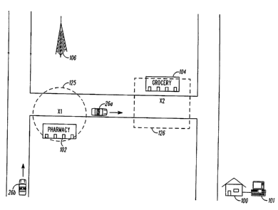
FIG. 3 illustrates two traveling vehicles 26a and 26b. Also illustrated is a
house 100 having a personal computer 101 therein, and two stores: a pharmacy
102
and a grocery 104. Also illustrated is a transceiver tower or base station 106
which
forms part of the communications network 10 as largely illustrated in FIG. 1.
The
vehicles 26a and 26b are in wireless communication with the system 10.
In a first embodiment, the first vehicle 26a desires to leave a message for
the
second vehicle 26b, in this case, instructing the second vehicle to stop at
the pharmacy
102 to pick up a prescription. In this first embodiment, the message is left
at the
CA 02561379 2006-09-26
WO 2005/101868 PCT/US2005/009442
current location of the first vehicle 26a which is leaving the message. Thus,
in this
embodiment, assume that the vehicle 26a was at a prior time at location X1
(i.e., at or
just before the pharmacy) when the first vehicle posted the message for the
second
vehicle 26b.
The first vehicle 26a can leave the message for the second vehicle 26b in a
i
number of different ways using the user interface 51 in the first vehicle.
FIG. 4a
illustrates one method using the display 79 and other aspects of the user
interface 51.
In this example, an occupant in the first vehicle 26a can enter the message
and other
pertinent information concerning the message using switches 113 on the user
interface
10 51 in the vehicle, which in this example would be similar to schemes used
to enter
names and numbers into a cell phone. The recipient information preferably
constitutes a user ID for an occupant in the second vehicle 26b which is
recognizable
by the system. Because the message may also have pertinence to a particular
time of
day, or time period during the day, or a particular day, or day of the week,
the first
vehicle 26a can also specify the dates and times at which the message should
be
transmitted to the second vehicle 26b. For example, if the message refers to
an item
that the second vehicle needs to pick up at a store after work, receipt of the
message at
a particular time of day (3:00-4:00 pm) may be the only pertinent time at
which the
message need be transmitted, and the first vehicle can so designate.
Accordingly, the
posting and expiration dates, time, periods, are specifiable.
Of course, many other less cumbersome ways may be used to textually enter
the message and other information. For example, in FIG. 4b, other switches 114
on
the user interface 51 are used to allow other message information to be easily
selected
without substantial typing on behalf of the first vehicle's occupant. Thus,
those users
CA 02561379 2006-09-26
WO 2005/101868 PCT/US2005/009442
11
in the second vehicle which are normally contacted by the users in the first
vehicles
can be loaded from memory 64 and correlated with switches 114 for easy
selection.
Similarly, the post time and expiration time for the message can be more
easily
entered using certain switches 114 as up/down buttons to adjust the time. (The
post
and expirations dates can be similarly adjusted in this fashion, although this
is not
shown). The disclosed schemes of FIGS. 4a and 4b are merely illustrative.
FIG. 4c illustrates another method using the display 79 and other aspects of
the user interface 51. In this example, an occupant in the first vehicle 26a
can enter a
global message and other pertinent information concerning the message using
switches 113 on the user interface 51 in the vehicle, which in this example
would be a
global message to other users regarding an accident. The recipient information
preferably constitutes people that may be affected by the message (even
broadly
defined as global). Because the message may also have pertinence to a
particular time
of day, or time period during the day, or a particular day, or day of the
week, the first
vehicle 26a can also specify the dates and times at which the message should
be
transmitted to anyone desiring to receive accident information. Accordingly,
the
posting and expiration dates, time, periods, are specifiable as well as a
radius of the
accident that any second vehicle must be within before having the message sent
to
them.
FIG. 4d illustrates a further method using the display 79 and other aspects of
the user interface 51. In this example, an occupant in the first vehicle 26a
can enter a
message that includes a data instruction and other pertinent information
concerning
the establishment of a communication link between the first vehicle 26a and a
second
vehicle 26b when a user is within a predetermined range of a location point.
The
CA 02561379 2006-09-26
WO 2005/101868 PCT/US2005/009442
12
recipient information preferably constitutes people that may be affected by
the
message (user 2 in the second vehicle 26b). Because the message may also have
pertinence to an instruction, the first vehicle 26a can also specify the type
of
instruction (place call to user 1 in the first vehicle 26a). A radius of a
location point
that any second vehicle must be within before establislung the communication
link
may also be specified in the message.
Messages and other pertinent message information can also be voice posted by
the first vehicle 26a using voice recognition module 70 (see FIG. 2). In this
regard, in
one embodiment, the voice recognition module 70 (which also may constitute
part of
the controller 56) is employed to process a received voice in the velucle and
to match
it to pre-stored voice prints stored in the voice recognition module 70. Many
such
voice recognition algorithms exist and are useable in the head unit 50, as one
skilled
in the art will appreciate. When a voice recognition module 70 is employed,
message
posting is made more convenient and less cumbersome, as an occupant in the
vehicle
can speak his message, the posting time, etc., and have it translated to text
for
eventual transmission to the second vehicle 26b. Moreover, the voice
recognition
module 70 may be used to verbally submit an intersection that is transmitted
to the
server 24 for translation into GPS or other latitude and longitude
coordinates.
The message can also be posted an as audio or video message. Thus, at an
appropriate time, the user interface 51 can prompt the user to speak the
message he
wants to send to the second vehicle 26b, which can be recorded using
microphone 6~.
Additionally, a video of the user leaving the message can be taken using video
camera
120, as shown in FIG. 5. Thus, instead of a text message, an audio or
streaming video
message can also be left for the second vehicle.
CA 02561379 2006-09-26
WO 2005/101868 PCT/US2005/009442
13
The message can also constitute a picture. For example, instead of informing
the second vehicle 26b to pick up the prescription at the pharmacy, the
message may
instead constitute a simple picture of the pharmacy to be displayed on display
79 of
the second vehicle's user interface 51 as a reminder. Such a picture can also
be
accompanied by a text or audio message. A picture can be taken using a camera
coupled or coupleable to the user interface 51 in the first vehicle (not
shown), and
which may reside outside of the vehicle:
While it is deemed beneficial in a preferred embodiment to allow posting of
the post time/expiration and time/date for the message, this is not strictly
required, as
the message can be posted immediately and indefinitely, or at least until the
message
is received by the second vehicle, as explained further below. Else, the
message can
simply "time out" after a set period and be deleted by the system.
In addition to any location information, the message sent from a user to the
server 24 may also include a direction and a velocity of the user. This
information
may be obtained from the navigation unit 62, the positioning unit 6, or other
vehicle
sensors. This type of information can be helpful in specific cases such as
accident
notifications and third party requests as mentioned above.
In any event, once the message, the intended recipient, and other posting
information (times, dates) are entered into the user interface 51 in the first
vehicle
26a, such information is sent by the controller 56 to the vehicle bus 60, to
the
Telematics control unit 40, and ultimately to the server 24, which may
constitute a
communications server and is hereinafter referred to as a server. As shown in
FIG. 6,
the server 24 stores the message, along with the sending user's system ID code
(user
ID1), the recipient's system ID code (user ID2), and other message particulars
such as
CA 02561379 2006-09-26
WO 2005/101868 PCT/US2005/009442
14
the postlexpiration time and date for the message. Other identity codes can
also be
used such as a phone number, a "handle," a Vehicle Identification number
(VIII, an
Electronic Serial Number (ESN), an International Mobile Subscriber Number
(IMSI),
or a Mobile Subscriber International ISDN Number (MSISDN), all of which are
referred to herein as "user IDs" for convenience.
In a further embodiment, the location at which the message was posted by the
first vehicle 26a (i.e., X1) is also stored with the message. Such location
information
may be automatically included with the posting by having the controller 56
query the
navigation unit 62 (see FIG. 2) to receive the location of the first vehicle
(i.e., its
latitude/longitude coordinates). Alternatively, the server 24 may also
determine or
calculate location information about a specific user 26 based on information
from
various cellular base stations in the proximity of the user 26. This can be
done by
triangulating information such as signal strength of communications of the
user with
the plurality of cellular base stations. In any event, when wirelessly
transmitting to
the server 24, the message and any associated information may be formatted in
any
number of ways. For example, the message may constitute the bulls of the data
stream, and may be accompanied by a header containing the user IDs, the
posting
dataltime, etc., in predictable formats so they will be easily interpreted by
the server
24. Once at the server 24, the information is preferably decompiled to
understand the
various pieces of information, and is stored in a file 122 as shown in FIG. 6.
However, it is not strictly necessary to send the exact location of the first
vehicle at the time the message is posted by the first vehicle. For example,
if the
navigation unit 62 sends location information to the server 24 frequently
enough, as
described in further detail below, location information can be sent without
the
CA 02561379 2006-09-26
WO 2005/101868 PCT/US2005/009442
message. Instead, the server 24, upon receipt of the message, can query the
last
reported position of the first vehicle 26a and associate that location with
the message.
In this regard, the idea of sending a message and location information to the
server 24
should be understood not to necessarily require simultaneous transmission of
the two.
5 At this point, the server 24 may calculate other information which will be
useful in eventually getting the message to the second vehicle 26a. For
example,
although it is desired to eventually send the message to the second vehicle
26b when
it arrives at the posted location X1, the second vehicle may not arrive
exactly at that
location. Thus, it is preferred to eventually send the message to the second
vehicle
10 26b when that vehicle is merely near to the location Xl. The server 24 may
therefore
compute an area around the location (X1) posted by the first vehicle 26a to
define and
store a message area, as is shown in FIG. 6. The area can constitute a subset
of
locations (i.e., longitude/latitude data), and may be defined either by a
radius around
the location (125, FIG. 3) or an area of some other shape such as a square or
rectangle
15 (126, FIG. 3). The area may also be defined as a corndor upstream and
downstream
along a route or as a segment of highway or street. If the communication
system is
broken up into a grid, the location X1 can also be associated to an
appropriate grid
square (such as 126). Such a radius or area can also be specified by the first
vehicle
26a and transmitted to the system 24 to allow the first vehicle to tailor the
reception
area for the message.
Additionally, the area prescribed can be a function of the message class. For
example, some messages from the first user can constitute emergencies (car
broken
down), work-related messages (here's where the meeting is), and purely
personal or
recreational messages (let's stop here to eat). Accordingly, the first vehicle
26a can
CA 02561379 2006-09-26
WO 2005/101868 PCT/US2005/009442
16
also allow selection of a message class indicator along with the message
(e.g., priority
"high," "medium," or "low"), with the area prescribed for receipt by the
second
vehicle 26b of the message scaling as a function of these message classes
("large,"
"medium," or "small").
In one embodiment, the locations of vehicles 26a and 26b (and any other users
connected to the system 10) are tracked by the server 24. In this regard, the
Telematics control unit 40 automatically transmits to the server 24 the
information
regarding the location and identity of the vehicles on a periodic basis.
Location
information is provided by the navigation unit 62 (FIG. 2). Identity
information can
constitute a user ID for the user in the first vehicle who is logged on to the
system, or
a phone number, a "handle," a Vehicle Identification number (VIN), an
Electronic
Serial Number (ESN), an International Mobile Subscriber Number (IMSI), or a
Mobile
Subscriber International ISDN Number (MSISDN) as noted earlier. In another
embodiment, the server 24 tracks the location of vehicles 26a and 26b using
information
received from cellular base stations to triangulate the position of particular
vehicles.
Because the location and identity of the vehicles or users are known to the
server 24, the server 24 can query the stored messages to determine when
message's
recipients are in an appropriate location to receive the message, whereafter
it is
broadcast. Thus, when the second user has approached the stored location X1
and/or
the message area (125) around it, and if the time and or date are appropriate
as
specifted with the message, the message can be broadcast to the second user
accordingly. The message can be wirelessly sent to the second user in the
second
vehicle 26b in much the same way that it was sent by the first vehicle 26a,
structured
with an appropriate and perhaps similar header. Of course, the second user
need not
CA 02561379 2006-09-26
WO 2005/101868 PCT/US2005/009442
17
receive all of the information sent by the first vehicle (e.g., the location
information),
although receipt of other information such as the sending user's ID can be of
benefit
as described below.
Alternatively, the server 24 can immediately transmit the message to the
second vehicle and the second vehicle 26b would then be responsible for
determining
when the second vehicle 26b has approached the stored location X1 and/or the
message area (125) around it, and if the time and or date are appropriate as
specified
with the message, the message can be displayed within the second vehicle
accordingly.
In any event, the message can be received at the user interface 51 of the
second vehicle 26b in any number of ways. For example, as shown in FIG. 7, the
message, if textual, can be displayed on the display 79 of the second
vehicle's user
interface, perhaps with some sort of visual or audible cue to be broadcast
through the
speakers 79, such as a "beep." Other useful information, such as the
post/expiration
time or day can also be displayed. Additionally, the display can prompt the
second
vehicle to acknowledge receipt of the message by pressing a button 114, or
such
confirmation can be automatically sent after the message has been displayed
for some
time. When confirmation is received by the server 24, the message may be
deleted
there, although it can remain stored in the memory 64 of the second vehicle's
26b
head unit 50 for some time to allow it again to be reviewed again by the
second
vehicle if necessary. In a further embodiment, the server 24 may send a
notification
to the first user or vehicle 26a notifying the user that the message was
received by the
second user or vehicle 26b.
CA 02561379 2006-09-26
WO 2005/101868 PCT/US2005/009442
18
The controller 56 of the second vehicle's user interface 51 can first display
or
broadcast a message notification indicator before the message is displayed or
broadcast to allow the operator of the second vehicle 26b to prepare for the
receipt of
the message. If beneficial, such a message notification indicator can be
selected by
the occupant in the second vehicle 26b to actually display or broadcast the
message,
perhaps by pressing a dedicated button on the user interface 51. This way, the
second
vehicle does not have to actually receive the message until a time that is
convenient.
Additionally, the user interface 51 at the second vehicle may require the
second
vehicle to enter a personal identification code such as a Personal
Identification
Number (P1N) prior to receiving the message. Such a PIN, like other aspects in
the
system, can be entered textually, by pressing buttons, or by voice
recognition. Upon
validation of the PIN at the server 24 (or at the controller 56), the message
can be sent
by the server 24 to the user interface 51, or if already sent; can be enabled
for display
or broadcast.
FIG. 8 shows another way in which the user can be notified of the message. In
this embodiment, the message is superimposed on a map, such as a directional
map
that the second user might otherwise be using to navigate. As the second
vehicle 26b
approaches the location (X1), the message will appear, assuming the time and
date are
appropriate. The map may be provided by the second vehicle's 26b head unit 50,
if so
equipped with such a program. Otherwise, a map displaying the location can be
formulated by the server 24 and sent along with the message, which saves the
trouble
of the second vehicle having to formulate a map and to associate it with the
location
in the message. Obviously, such a modification is particular beneficial if the
second
vehicle 26b is unable to formulate its own map.
CA 02561379 2006-09-26
WO 2005/101868 PCT/US2005/009442
19
The message can also be audibly (through speakers 7~) or visually (on display
79) broadcast at the user interface 51 in the second vehicle 26b, which is
particularly
useful if the message is an audio message or a video message as discussed
earlier.
Such broadcast may also be accompanied by displaying of other useful
information on
the display 79 such as shown in FIG. 7.
Although it is particularly beneficial to display or broadcast the message to
the
second vehicle 26b when it is in the vicinity of the location specified in the
message,
the second vehicle 26b may wish to know what messages have been posted to hirn
even prior to his arrival at those locations. Accordingly, messages posted for
the
second vehicle can be sent even in advance of the second vehicle approaching
the
location of interest (e.g., Xl), as shown in FIGS. 9-11. As shown in FIG. 9,
three
such messages have been posted for receipt at the user interface 51 of the
second
vehicle 26b and are superimposed on a map to show the locations where the
messages
are pertinent. When the second vehicle 26b moves into vicinity of those
messages, ,
the messages may change in color or otherwise become more pronounced; or, an
audible alarm may sound; or confirmation of receipt of the message may be sent
at
that time.
The second vehicle's messages can also be displayed in simple text form along
with their location data, as shown at FIG. 10. Because displaying raw location
information (longitude/latitude data) in this circumstance is less informative
than
when a map is used (FIG. 9), location information may be simplified by the
server 24
by displaying, for example, a street address. In this regard, a mapping
program can be
implemented on the server 24 to effectuate a location data-to-street address
conversion, as one skilled in the art understands.
CA 02561379 2006-09-26
WO 2005/101868 PCT/US2005/009442
The second vehicle's messages, should they be audio or video messages, can
be displayed as links, as shown in FIG. 11 so that they may be reviewed even
in
advance of arnval at the locations of interest. The links may be selected
using
selection buttons 114. Of course, these messages are preferably also broadcast
when
5 the second vehicle 26b arrives at the location specified by the first user.
FIGS. 9-11 also illustrate another flexible aspect of the disclosed message
posting system, namely the ability of a user to leave a location-based message
for
himself rather than another system user. This is illustrated as message 130,
in wluch
the second vehicle 26b has left a message for himself at location X3. This can
be
10 accomplished in much the same way as the first vehicle 26a leaves a message
for the
second vehicle 26b. Essentially, the second vehicle 26b travels to the
location (X3)
and posts a message specifying his own user address, using any of the
techniques
disclosed earlier (e.g., FIGS. 4a-4c). This way the second vehicle (or any
other user
of the system) can leave a location-based message for themselves. For example,
in
15 the example of FIGS. 9-11, the second user, while driving passed the
service station at
location X3 might decide that he needs to remember to get his oil changed in
the next
couple of weeks, and accordingly can leave himself a message which will post
at an
appropriate date or time period two weeks in the future.
To this point, this disclosure has described embodiments in which a user
20 travels to a particular location to post a message for himself or another
user at that
location. However, in other embodiments, a user of the system 10 need not be
present
at a location to leave a message for himself or another user at that location.
This
aspect is illustrated by again referring to FIG. 3, in which a system user
located at a
house 100 posts a message for the second vehicle 26b using a computer 101. In
this
CA 02561379 2006-09-26
WO 2005/101868 PCT/US2005/009442
21
example, the home user wishes to instruct the second vehicle to pick up a
gallon of
milk from the grocery store 104 (FIG. 3) located at X2. Posting of such a
message
can be done in a number of ways, as illustrated by the computer's 101 monitor
in FIG.
12. For example, a map of an area can be pulled up on the monitor by the home
user.
The home user can then use a mouse pointer 140 to point to the location where
the
message is to be left (denoted by an X). After clicking this position, a
window 142
can be made to pop up on the monitor, which contains blanks for the home user
to
input (e.g., type on a keyboard associated with the computer 101) the message
and
other message particulars, such as expiration time and date. Alternatively,
the home
user could first type in the second vehicle's user ID ([user ID2]), to first
locate the
second vehicle and display that location on the map. (This is feasible
because, as
noted earlier, in a preferred embodiment all users on the system periodically
report in
to the server 24 with identity and location information). If the second
vehicle 26b is
displayed, his user ID may be displayed above a representation of that vehicle
as
shown, and instead of having to type in the second vehicle's user ID, the home-
user
may merely click on that representation to load it into window 142. Either
way, once
the location (X) and the message and its particulars are entered, the message
can be
sent to the server 24 (and ultimately the second vehicle 26b) by moving the
pointer
140 to the "send" button and clicking it.
Of course, a non-mobile home user who anticipates being mobile at a later
time can also leave message for himself by entering his own user ID into the
computer 101.
Although illustrated with respect to an essentially non-mobile home user,
mobile system users can also leave messages for others (or themselves) at
locations
CA 02561379 2006-09-26
WO 2005/101868 PCT/US2005/009442
22
where they are not located. In this regard, the controllers 56 in the user
interfaces 51
in the vehicles could be made to run the same program as illustrated in FIG.
12 for the
home user. Or the techniques disclosed earlier for posting of a message from a
vehicle can be used, with the added aspect of also having to disclose the
location of
interest where the message should be posted.
Although the disclosed system and method are illustrated as being useful to
leave
a message with a single system user, it is also possible to leave a single
message with
numerous users, assuming their user ms are also specified when the message is
posted.
Moreover, a single message to a single participant can be associated with a
number of
locations. This feature might be useful for example if the recipient needs to
go to one of a
particular chain of stores.
While largely described with respect to improving communications within
vehicles, one skilled in the art will understand that many of the concepts
disclosed
herein could have applicability to other portable communicative user
interfaces not
contained within vehicles, such as cell phones, personal data assistants
(PDAs),
portable computers, etc., what can be referred to collectively as portable
communication devices.
Although several discrete embodiments are disclosed, one skilled in the art
will appreciate that the embodiments can be combined with one another, and
that the
use of one is not necessarily exclusive of the use of other embodiments.
Moreover,
the above description of the present invention is intended to be exemplary
only and is
not intended to limit the scope of any patent issuing from this application.
The
present invention is intended to be limited only by the scope and spirit of
the
following claims.