Note: Descriptions are shown in the official language in which they were submitted.
CA 02561444 2006-09-28
WO 2005/096725
PCT/US2005/010165
1
ARTICULATING WORK PLATFORM SUPPORT SYSTEM,
WORK PLATFORM SYSTEM,
AND METHODS OF USE THEREOF
BACKGROUND OF THE INVENTION
1. Technical Field
The invention relates, generally, to the field of construction and temporary
work
platforms that are erected to access various parts of various structures.
Specifically, the
invention relates to a unique articulating work platform support system, a
work platform system,
the various pieces of such systems and methods of using and manufacturing the
same.
2. Related Art
Current work platform structures suffer from numerous deficiencies and
shortcomings.
Paramount to all work platforms that are suspended above the ground is the
safety of the workers
using them. For all work platform systems, in order to be legal, must meet
numerous regulations
promulgated by the U.S. Department of Labor Occupational Safety and Health
Administration
(i.e., "OSHA"). Many work platform systems currently used in the marketplace
are believed to
not meet all of these OSHA regulations.
Additionally, in the construction industry, costs are always of significant
importance.
Whether the construction project is a public works project (e.g., low bid), or
a private project,
reducing and/or maintaining costs is critical to the contractor(s) and the
owner. Reducing labor,
material, and/or equipment costs all help to address the all important cost.
In the area of work platforms and support systems, a significant portion of
the cost is for
the labor to erect and disassemble.
Some current work platform systems, require full assembly remote from the
final
installation location (e.g., on the ground; in a construction "yard", etc.),
and then transporting
CA 02561444 2011-09-14
- 72037-169
2
.
(e.g., jacking, winching, lifting, moving, etc.) the assembled work platform
into its
requisite final location on the job site. This "build-then-move" aspect of
many work
platform systems is time consuming and requires significant labor and
equipment to
complete.
In summary, a need exists to overcome the above stated, and other,
deficiencies in the art of work platform and work platform support systems. A
need
exists for an improved system that clearly meets, and exceeds, all OSHA
regulations,
while also requiring reduced time, labor, and equipment, to assemble, move,
extend,
and disassemble.
SUMMARY OF THE INVENTION
Aspects of the present invention provide a device for use with work
platform system, a work platform support system, a work platform system, and a
method of manufacturing and installing same.
According to an aspect of the present invention, there is provided a
work platform support system comprising: a plurality of joists; and a
plurality of hubs;
wherein the plurality of joists comprises four joists and wherein the
plurality of hubs
comprises four hubs; wherein the joists and hubs are configured to be
interconnected
so that: i) one of the joists and two of the hubs are to remain stationary;
ii) two of the
joists are rotatable; and iii) two of the hubs and one of the joists are
translatable;
wherein the joists and hubs are to be interconnected so that the two rotatable
joists,
the two translatable hubs, and the one translatable joist can articulate from
an initial
position to a final position with respect to the stationary joist and the
stationary hubs;
wherein the plurality of joists are substantially co-planar with respect to
each other in
the initial and the final position; wherein at least one of the joists is to
be connected
with at least one of the hubs using a pin to provide free rotation of the at
least one
joist with respect to the at least one hub about the pin; and wherein the free
rotation
is restricted by at least one of: i) an additional pin that is to be located
proximate a
perimeter of the at least one hub; and ii) at least a portion of a work
platform when
the platform is positioned with respect to the hubs and the joists in the
final position.
CA 02561444 2011-09-14
. 72037-169
. 3
According to another aspect of the present invention, there is provided
a work plafform support system comprising: at least four hubs; and at least
four
joists, each of the four joists are configured to be interconnected with at
least two of
the four hubs; wherein the joists and the hubs are configured to be
interconnected so
that: i) one of the joists-and two of the hubs-are configured to remain
stationary; ii)
two of the joists-are rotatable; and iii) two of the hubs-and one of the
joists-are
translatable; wherein, when interconnected, the two rotatable joists, the two
translatable hubs, and the one translatable joist can articulate from an
initial position
to a final position with respect to the stationary joist and the stationary
hubs; wherein
the at least four joists-are substantially co-planar with respect to each
other in the
initial and the final positions; wherein at least one of the joists is
configured to be
connected with at least one of the hubs using a pin to provide free rotation
of the at
least one joist with respect to the at least one hub about the pin; and
wherein the free
rotation is restricted by at least one of: i) an additional pin that is to be
located
proximate a perimeter of the at least one hub; and ii) at least a portion of a
work
platform when the plafform is positioned with respect to the hubs and the
joists in the
final position.
According to another aspect of the present invention, there is provided
a work platform support system for suspending a work platform from a
structure; said
system comprising: a plurality of joists; at least one of a plurality of hubs
for
interconnecting at least two of said plurality of joists; and a suspension
connector for
suspending at least one of the plurality of joists and at least one of the
plurality of
hubs from a structure; wherein the plurality of joists comprises four joists
and wherein
the plurality of hubs comprises four hubs; wherein the joists and hubs are
configured
to be interconnected so that: i) one of the joists and two of the hubs are to
remain
stationary; ii) two of the joists are rotatable; and iii) two of the hubs and
one of the
joists are translatable; wherein, when interconnected, the two rotatable
joists, the two
translatable hubs, and the one translatable joist can articulate from an
initial position
to a final position with respect to the stationary joist and the stationary
hubs; wherein
the plurality of joists are substantially coplanar with respect to each other
in the initial
CA 02561444 2011-09-14
72037-169
4
and the final positions; and wherein at least one of the joists is configured
to be
connected with at least one of the hubs using a pin to provide free rotation
of the at
least one joist with respect to the at least one hub about the pin; and
wherein the free
rotation is restricted by at least one of: i) an additional pin that is to be
located
proximate a perimeter of the at least one hub; and ii) at least a portion of a
work
platform when the platform is positioned with respect to the hubs and the
joists in the
final position.
According to another aspect of the present invention, there is provided
a work platform support structure comprising: a first hub connectable in fixed
relation
to a second hub using a first joist; and a third hub connectable to a fourth
hub using a
second joist, the third and the fourth hubs further connectable to the first
and the
second hubs using third and fourth joists; wherein, when connected, the
second, the
third and the fourth joists, and the third and the fourth hubs articulate from
an initial
position to an extended position with respect to the first and second hubs and
the first
joist; wherein, when connected, each of the first, second, third and the
fourth joists
extends substantially perpendicularly with respect to an axis of at least one
of the
respective first, second, third and fourth hubs about which the respective
joists rotate;
wherein the first, second, third and the fourth joists are substantially co-
planar with
respect to each other in the initial and the extended positions; wherein at
least one of
the joists is to be connected with at least one of the hubs using a pin to
provide free
rotation of the at least one joist with respect to the at least one hub about
the pin; and
wherein the free rotation is restricted by at least one of: i) an additional
pin that is
configured to be located proximate a perimeter of the at least one hub; and
ii) at least
a portion of a work platform when the platform is positioned with respect to
the hubs
and the joists in the extended position.
According to another aspect of the present invention, there is provided
a work platform support structure comprising: a first pair of hubs connectable
in fixed
relation to each other using a first joist; and a second pair of hubs
connectable to
each other using a second joist, the second pair of hubs further connectable
to the
first pair of hubs using third and fourth joists; wherein, when connected, the
second,
CA 02561444 2011-09-14
. 72037-169
the third and the fourth joists and the second pair of hubs articulate from an
initial
position to a final position with respect to the first pair of hubs and the
first joist;
wherein, when connected, each of the first, second, third and the fourth
joists extends
substantially perpendicularly with respect to an axis of at least one of the
respective
5 hubs in the first and the second pair of hubs about which the respective
joists rotate;
and wherein the first, second, third and the fourth joists are substantially
co-planar
with respect to each other in the initial and the final positions; wherein at
least one of
the joists is configured to be connected with at least one of the hubs using a
pin to
provide free rotation of the at least one joist with respect to the at least
one hub about
the pin; and wherein the free rotation is restricted by at least one of: i) an
additional
pin that is to be located proximate a perimeter of the at least one hub; and
ii) at least
a portion of a work platform when the plafform is positioned with respect to
the hubs
and the joists in the final position.
According to another aspect of the present invention, there is provided
a work platform structure comprising: a first hub and joist assembly
comprising pair
of hubs connectable in fixed relation to each other using a first joist; a
second hub
and joist assembly comprising a pair of hubs connectable to each other using a
second joist, the pair of hubs further connectable to third and fourth joists;
wherein,
when connected, the second hub and joist assembly articulates with respect to
the
first hub and joist assembly; wherein, when connected, each of the joists in
the first
and the second hub and joist assemblies extends substantially perpendicularly
with
respect to an axis of at least one of the respective first, second, third and
fourth hubs
about which the respective joists rotate; wherein, when connected, each of the
joists
in the first and the second hub and joist assemblies is substantially coplanar
with
respect to each other in an initial position and an extended position; and
wherein at
least one of the joists is configured to be connected with at least one of the
hubs
using a pin to provide free rotation of the at least one joist with respect to
the at least
one hub about the pin; and wherein the free rotation is restricted by at least
one of: i)
an additional pin that is to be located proximate a perimeter of the at least
one hub;
CA 02561444 2011-09-14
. 72037-169
6
and ii) at least a portion of a work plafform when the plafform is positioned
with
respect to the hubs and the joists in the extended position.
According to another aspect of the present invention, there is provided
a work platform support structure comprising: a first joist having fixed first
and
second hubs connectable thereto; a rotatable second joist connectable to
either the
first or the second hub, a rotatable third joist connectable to the other of
the first or
the second hub; a third hub connectable to either the rotatable second joist
or the
rotatable third joist and a fourth hub connectable to the other of the second
or the
third joist; and a fourth joist connectable to the third and the fourth hubs;
wherein,
when connected, the second, third and fourth joists and the third and fourth
hubs
together articulate with respect to the stationary first joist and fixed first
and second
hubs from an initial position to a final position in which a work platform can
be
received and supported; wherein at least one of the joists is to be connected
with at
least one of the hubs using a pin to provide free rotation of the at least one
joist with
respect to the at least one hub about the pin; wherein the free rotation is
restricted by
at least one of: i) an additional pin that is to be located proximate a
perimeter of the at
least one hub; and ii) at least a portion of a work platform when the plafform
is
positioned with respect to the hubs and the joists in the final position;
wherein each of
the first, second, third and the fourth hubs comprises a first surface with a
first set of
openings; a second surface substantially parallel to said first surface and
having a
second set of openings; and a structural element connected between the first
surface
and the second surface, such that each one of the openings in the first set of
openings is co-axial with a respective one of the openings in the second set
of
openings; and wherein the first, second, third and the fourth joists are
substantially
co-planar with respect to each other in both the initial and the final
positions.
CA 02561444 2011-09-14
72037-169
7
According to another aspect of the present invention, there is provided
a work platform support structure comprising: a first hub and joist assembly
comprising a first joist and a pair of hubs connectable to the first joist;
and a second
hub and joist assembly comprising a rotatable second joist, a rotatable third
joist and
a translatable fourth joist, the second, third and fourth joists connectable
together
using a pair of hubs; wherein at least two of the three joists of the second
hub and
joist assembly are connectable to the hubs of the first hub and joist
assembly;
wherein, when connected, the second hub and joist assembly articulates with
respect
to the first hub and joist assembly in order to receive and support a work
plafform;
wherein each of the hubs in the first and the second hub and joist assemblies
comprises a first surface with a first set of openings; a second surface
substantially
parallel to said first surface and having a second set of openings; and a
structural
element connected between the first surface and the second surface, such that
each
one of the openings in the first set of openings is co-axial with a respective
one of the
openings in the second set of openings; wherein, when connected, each of the
joists
in the first and the second hub and joist assemblies is substantially coplanar
with
respect to each other in a first initial position and a second extended
position;
wherein at least one of the joists is configured to be connected with at least
one of
the hubs using a pin to provide free rotation of the at least one joist with
respect to
the at least one hub about the pin; and wherein the free rotation is
restricted by at
least one of: i) an additional pin that is to be located proximate a perimeter
of the at
least one hub; and ii) at least a portion of a work platform when the platform
is
positioned with respect to the hubs and the joists in the extended position.
According to another aspect of the present invention, there is provided
a work plafform assembly comprising: first, second, third and fourth hubs,
each of
the hubs comprising a first surface with a first set of openings; a second
surface
substantially parallel to said first surface and having a second set of
openings, such
that each one of the openings in the first set of openings is co-axial with a
respective
one of the openings in the second set of openings; and a structural element
connected between the first surface and the second surface such that a
longitudinal
CA 02561444 2011-09-14
. 72037-169
8
.
axis of the structural element is at least substantially normal to the planes
of the first
and the second surfaces; first, second, third and fourth joists adapted for
operable
association with the first, second, third and fourth hubs, such that, when so
associated, each of the first, second, third and the fourth joists extends
substantially
perpendicularly with respect to an axis of at least one of the respective
first, second,
third and the fourth hubs about which the respective joists can rotate; a work
platform
that is adapted to be positioned upon at least one of the first, second, third
and the
fourth joists, at least one of the first, second, third and the fourth hubs,
or a
combination thereof, when the hubs and joists are operably associated, to form
a
work platform system; wherein, when operably associated, (i) the first hub is
connected in fixed relation to the second hub using the first joist; (ii) the
third hub is
connected to the fourth hub using the second joist-and (iii) the third and the
fourth
joists are connected to the first and the third, and the second and the fourth
hubs
respectively; wherein, when operably associated, at least one of the second,
third
and the fourth joists, and at least one of the third and the fourth hubs
articulate from
an initial position to a final position by at least one of translating,
rotating and pivoting
with respect to the first and the second hubs and the first joist to obtain a
closed-loop
structure such that the first and the third joists are parallel or
substantially parallel to
the second and the fourth joists respectively in the final position upon
articulation;
wherein each of the first, second, third and fourth joists is substantially co-
planar in
the initial and the final positions; wherein at least one of the joists is
configured to be
connected with at least one of the hubs using a pin to provide free rotation
of the at
least one joist with respect to the at least one hub about the pin; and
wherein the free
rotation is restricted by at least one of: i) an additional pin that is to be
located
proximate a perimeter of the at least one hub; and ii) at least a portion of a
work
plafform when the plafform is positioned with respect to the hubs and the
joists in the
final position.
According to another aspect of the present invention, there is provided
a work plafform support structure comprising: a first hub connectable in fixed
relation
to a second hub using a first joist; a third hub connectable to a fourth hub
using a
CA 02561444 2011-09-14
72037-169
8a
second joist, the third and the fourth hubs further connectable to the first
and the
second hubs using third and fourth hoists; wherein, when connected, the
second, the
third and the fourth joists, and the third and the fourth hubs articulate with
respect to
the first and second hubs and the first joist to an extended or final
position; wherein at
least one of the joists is connectable with at least one of the hubs using a
pin to
provide free rotation of the at least one joist with respect to the at least
one hub about
the pin; and wherein the free rotation is restricted by at least one of: i) an
additional
pin that is to be located proximate a perimeter of the at least one hub; and
ii) at least
a portion of a work platform when the plafform is positioned with respect to
the hubs
and the joists in the extended or final position.
According to another aspect of the present invention, there is provided
a method of installing an additional work plafform system module with respect
to a
first work plafform system module which is part of a work plafform system that
is
suspended from a structure, the method comprising: providing a first work
platform
system module as part of a work plafform system that is suspended from a
structure,
the first work platform system module comprising a first work plafform support
system
module having a pair of hubs, a joist connected to and in operable association
with
the pair of hubs, and a first work plafform, the first work platform supported
by the
support system module; providing an additional hub and a plurality of
additional joists;
connecting the additional hub to the additional joists and the additional
joists to the
pair of hubs of the first work platform support system module to form an
additional
work platform support system module; articulating the additional hub and the
additional joists from a first position in which at least one of the joists of
the additional
work platform support system module is least substantially parallel to the
joist of the
first work plafform system module to a second position in which at least one
of the
joists of the additional work platform support system module is at least
substantially
perpendicular to the joist of the first work plafform system module; and
positioning an
additional work platform on the additional work platform support system
module,
thereby installing the additional work platform system module which one of or
both
CA 02561444 2011-09-14
72037-169
8b
(1) extends from and (2) is connected to the first work platform system module
which
is part of the work platform system that is suspended from the structure.
According to another aspect of the present invention, there is provided
a method of installing an additional work platform system module with respect
to a
first work platform system module which is part of a work platform system that
is
suspended from a structure, the method comprising: providing a first work
platform
system module as part of a work platform system that is suspended from a
structure,
the first work platform system module comprising a first work platform support
system
module having a pair of hubs, a joist connected to and in operable association
with
the pair of hubs, and a first work platform, the first work platform supported
by the
support system module; providing an additional hub and a plurality of
additional joists;
connecting the additional hub to the additional joists and the additional
joists to the
pair of hubs of the first work platform support system module to form an
additional
work platform support system module, articulating the additional work plafform
support system module from a first position to a second position; and
positioning an
additional work plafform on the additional work plafform support system
module,
thereby installing an additional work platform system module; wherein the
connecting
includes using a pin that can provide free rotation of the at least one of the
plurality of
additional joists with respect to the additional hub about the pin; and
wherein the free
rotation is restricted by at least one of: i) an additional pin located
proximate a
perimeter of the additional hub; and ii) at least a portion of the additional
work
platform when the plafform is positioned with respect to additional hub and
the
plurality of additional joists in the final position.
According to another aspect of the present invention, there is provided
an interconnection structure for interconnection with an elongate structural
member,
the interconnection structure comprising: an element having a plurality of
openings;
an additional element having a plurality of openings located so that at least
a
respective one of the plurality of the openings of the element is coaxial with
at least a
respective one of the plurality of openings of the additional element to
create at least
one respective pair of coaxial openings; and a section connected between the
CA 02561444 2011-09-14
. 72037-169
8c
element and the additional element; wherein at least one of the element and
the
additional element includes a support opening, the support opening disposed
generally at or about a center of the respective at least one element and
additional
element, and the support opening is configured to receive a suspension
connector,
such as a chain, and permit retaining of the suspension connector at a
location away
from the center of the respective at least one element and additional element.
According to another aspect of the present invention, there is provided
a method of using an interconnection structure, the method comprising:
providing an
interconnection structure comprising: an element having a plurality of
openings; an
additional element having a plurality of openings located so that at least a
respective
one of the plurality of the openings of the element is coaxial with at least a
respective
one of the plurality of openings of the additional element to create at least
one
respective pair of coaxial openings; and a section connected between the
element
and the additional element, and wherein at least one of the element and the
additional element includes a support opening, the support opening disposed
generally at or about a center of the respective at least one element and
additional
element; receiving a free end of a suspension connector by way of the at least
one
support opening in the element; retaining the end of the connector at a
location away
from the center of the respective at least one element and additional element.
According to another aspect of the present invention, there is provided
an interconnection structure in combination with an auxiliary mounting
bracket, the
combination comprising: an interconnection structure for interconnection with
an
elongate structural member, the interconnection structure comprising: an
element
having a plurality of openings; an additional element having a plurality of
openings
located so that at least a respective one of the plurality of the openings of
the element
is coaxial with at least a respective one of the plurality of openings of the
additional
element to create at least one respective pair of coaxial openings; and a
section
connected between the element and the additional element; and an auxiliary
suspender mounting bracket configured for connection with a suspension
connector
for suspension from another structure.
CA 02561444 2011-09-14
72037-169
8d
According to another aspect of the present invention, there is provided
a work platform support structure comprising: a first interconnection
structure
connectable in fixed relation to a second interconnection structure using a
first
elongate structural member; a third interconnection structure connectable to a
fourth
interconnection structure using a second elongate structural member, the third
and
the fourth interconnection structures further connectable to the first and the
second
interconnection structures using third and fourth elongate structural members;
wherein, when connected, the second, the third and the fourth elongate
structural
members, and the third and the fourth interconnection structures articulate
with
respect to the first and second interconnection structures and the first
elongate
structural member to an extended or final position; wherein at least one of
the
elongate members is connectable with at least one of the interconnection
structures
using a pin to provide free rotation of the at least one elongate member with
respect
to the at least one interconnection structure about the pin; wherein the free
rotation is
restricted by at least one of: i) an additional pin that is to be located
proximate a
perimeter of the at least one interconnection structure; and ii) at least a
portion of a
work platform when the platform is positioned with respect to the
interconnection
structures and the elongate members in the extended or final position; and
wherein
each interconnection structure includes: an element having a plurality of
openings; an
additional element having a plurality of openings located so that at least a
respective
one of the plurality of the openings of the element is coaxial with at least a
respective
one of the plurality of openings of the additional element to create at least
one
respective pair of coaxial openings; and a section connected between the
element
and the additional element; and wherein at least one of the element and the
additional element includes a support opening, the support opening disposed
generally at or about a center of the respective at least one element and
additional
element, and the support opening is configured to receive a suspension
connector,
such as a chain, and permit retaining of the suspension connector at a
location away
from the center of the respective at least one element and additional element.
A general aspect provides an apparatus comprising:
CA 02561444 2011-09-14
. 72037-169
8e=
a plurality of joists; and
a plurality of hubs pivotally attached to said plurality of joists, wherein
said plurality of hubs are adapted to receive a work platform.
Another general aspect provides a work plafform support system
comprising:
a plurality of joists;
a plurality of hubs, wherein each hub operatively connects to at least
two joists; and
further wherein said system is configured to be articulating.
Another general aspect provides a work plafform system comprising:
a plurality of joists;
a plurality of hubs, wherein each hub pivotally connects to at least two
joists; and
at least one work plafform which rests on at least one of said plurality of
joists, said plurality of hubs, or a combination thereof.
Another general aspect provides a device for interconnecting with at
least one joist of a work plafform support system comprising:
a first surface with a first set of openings;
a second surface substantially parallel to said first surface, said second
surface having a second set of openings; and
a structural element interspersed between said first surface and said
second surface, wherein at least one of said first set and said second set of
openings
CA 02561444 2011-09-14
. 72037-169
8f
is adapted to provide an articulation of said device when interconnected with
said at
least one joist.
Another general aspect provides a work plafform system comprising:
at least one hub;
at least one joist interconnected with said at least one hub; and
at least one section formed from said at least one hub and said at least
one joist, wherein said at least one section can be articulated from a first
position into
a second position, further wherein said at least one section is capable of
supporting
without failure its own weight and at least about four times the maximum
intended
load applied or transmitted to it.
Another general aspect provides a work plafform system for suspending
a work platform from a structure, said system comprising:
a plurality of joists;
at least one hub for interconnecting at least two of said plurality of joists,
wherein said at least two joists may articulate; and
a suspension connector for suspending said system from said structure.
Another general aspect provides method comprising:
providing a plurality of joists; and
pivotally attaching at least one hub to at least two of said plurality of
joists, wherein said at least one hub is adapted to receive a work platform.
Another general aspect provides a method of installing a work plafform
support system to a structure comprising:
providing a plurality of joists;
CA 02561444 2011-09-14
= 72037-169
8g=
providing at least one hub;
pivotally attaching at least one hub to said plurality of joists; and
suspending said at least one hub from said structure.
Another general aspect provides method of extending a second work
plafform system from a first, suspended work plafform system, said method
comprising:
attaching a plurality of joists to said first system;
attaching a plurality of hubs to said plurality of joists;
articulating said plurality of joists and plurality of hubs, thereby forming
said extending second work platform system.
The foregoing and other features and advantages of the invention will
be apparent from the following more particular description of embodiments of
the
invention. It is to be understood that both the foregoing general description
and the
following detailed description are exemplary, but are not restrictive, of the
invention.
BRIEF DESCRIPTION OF THE DRAWINGS
The features of the present invention will best be understood from a
detailed description of the invention and an embodiment thereof selected for
the
purposes of illustration and shown in the accompanying drawings in which:
FIG. 1 is top perspective view of a hub, in accordance with an
embodiment of the present invention;
FIG. 2 is top view of a hub, in accordance with an embodiment of the
present invention;
FIG. 3 is a side elevation view of an embodiment of a hub, in
accordance with the present invention;
CA 02561444 2011-09-14
. 72037-169
8h
FIG. 4 is bottom view of a hub, in accordance with an embodiment of
the present invention;
FIG. 5 is a top perspective view of a hub and joist, in accordance with
an embodiment of the present invention;
FIG. 6A is an exploded top perspective view of an interconnection
between a hub and joist, in accordance with an embodiment of the present
invention;
FIG. 6B is a top perspective view of the view in FIG. 6A, in accordance
with an embodiment of the present invention;
FIG. 7 is a top perspective view of a work plafform support system, in
accordance with an embodiment of the present invention;
FIG. 8A is a top perspective view of an interconnection between a joist
and deck support, in accordance with an embodiment of the present invention;
FIG. 8B is a exploded reverse top perspective view of an
interconnection between a joist and deck support, in accordance with an
embodiment
of the present invention;
FIG. 8C is a close-up top perspective view of an interconnection
between a joist and deck support, in accordance with an embodiment of the
present
invention;
FIG. 9 is a top perspective view of a work platform support system and
work platform system, in accordance with an embodiment of the present
invention;
FIG. 10 is a top perspective view of a second embodiment of a work
platform support system and work platform system, in accordance with the
present
invention;
FIG. 11A is a top perspective view of a joist, hub, and portion of a deck
retainer assembly, in accordance with an embodiment of the present invention;
CA 02561444 2011-09-14
. 72037-169
8i
FIG. 11B is an exploded close-up perspective view of a joist, hub, and
portion of a deck retainer assembly, in accordance with an embodiment of the
present invention;
FIG. 11C is an end sectional view of a joist and a portion of a deck
retainer assembly, in accordance with an embodiment of the present invention;
FIG. 12 is a top perspective view of a third embodiment of a work
platform support system and work platform system, in accordance with the
present
invention;
FIG. 13 is a bottom perspective view of the embodiment shown in
FIG. 12, in accordance with the present invention;
FIG. 14 is a top perspective view of a work plafform system and a work
platform support system prior to articulation, in accordance with an
embodiment of
the present invention;
FIG. 15 is atop perspective view of the embodiment in FIG. 14
undergoing articulation, in accordance with the present invention;
FIG. 16 is atop perspective view of the embodiment in FIG. 15
undergoing further articulation, in accordance with the present invention;
FIG. 17 is a top perspective view of the embodiment in FIG. 16
undergoing further articulation, in accordance with the present invention;
FIG. 18 is a top perspective view of the embodiment in FIG. 14 having
completed articulation, in accordance with the present invention;
FIG. 19A is a top perspective view of a joist and hub assembly, in
accordance with an embodiment of the present invention;
FIG. 19B is a top perspective view of a second embodiment of a joist
and hub assembly, in accordance with the present invention;
CA 02561444 2011-09-14
= 72037-169
8j=
FIG. 19C is a top perspective view of a third embodiment of a joist and
hub assembly, in accordance with the present invention;
FIG. 19D is a top perspective view of a fourth embodiment of a joist and
hub assembly, in accordance with the present invention;
FIG. 20A is a plan view of a curved work platform support system, in
accordance with an embodiment of the present invention;
FIG. 20B is a plan view of an angled work platform support system, in
accordance with an embodiment of the present invention;
FIG. 21A is a top perspective view of an interconnection between a hub
and a railing standard, in accordance with an embodiment of the present
invention;
FIG. 21B is a close-up of FIG. 21A, in accordance with an embodiment
of the present invention;
FIG. 21C is an exploded view of FIG. 21B, in accordance with an
embodiment of the present invention;
FIG. 22A is a top perspective view of a railing standard and railing, in
accordance with an embodiment of the present invention;
FIG. 22B is an exploded view of FIG. 22C, in accordance with an
embodiment of the present invention;
FIG. 22C is a close up top perspective view of an interconnection
between a railing standard and railing, in accordance with an embodiment of
the
present invention;
FIG. 23 is a sectional elevation view of a work plafform support system
and work plafform system attached to a structure, in accordance with an
embodiment
of the present invention;
CA 02561444 2011-09-14
. 72037-169
. 8k
FIG. 24A is a top perspective view of an interface between a hub and a
suspension connector, in accordance with an embodiment of the present
invention;
FIG. 24B is a close-up of the interface shown in FIG. 24A, in
accordance with an embodiment of the present invention;
FIG. 25A is a sectional elevation view of a hub, suspension connector,
and structure attachment device, in accordance with an embodiment of the
present
invention;
FIG. 25B is a close-up sectional elevation view of the interconnection
between the hub and suspension connector, in accordance with an embodiment of
the present invention;
FIG. 26A is a top, perspective view of an auxiliary suspender mounting
bracket, in accordance with an embodiment of the present invention;
FIG. 26B is a plan view of an auxiliary suspender mounting bracket, in
accordance with an embodiment of the present invention;
FIG. 26C is a front elevation view of an auxiliary suspender mounting
bracket, in accordance with an embodiment of the present invention;
FIG. 26D is a side elevation view of an auxiliary suspender mounting
bracket, in accordance with an embodiment of the present invention;
FIG. 27 is an elevation sectional view showing suspension of a work
platform system from a structure via an auxiliary suspender mounting bracket,
in
accordance with an embodiment of the present invention;
FIG. 28A is an elevation view of a work platform system suspended
under an arched bridge, in accordance with an embodiment of the present
invention;
CA 02561444 2011-09-14
- 72037-169
, 81
FIG. 28B is an elevation view of a second embodiment of a work
plafform system suspended under an arched bridge, in accordance with the
present
invention;
FIG. 28C is an elevation view of a multi-leveled work platform system
suspended under a structure, in accordance with an embodiment of the present
invention; and
FIG. 29 is an elevation view of load test set up conducted on an
embodiment of the present invention.
DETAILED DESCRIPTION OF EMBODIMENTS
Although certain preferred embodiments of the present invention will be
shown and described in detail, it should be understood that various changes
and
modifications may be made without departing from the scope of the appended
claims.
The scope of the present invention will in no way be limited to the number of
constituting components, the materials thereof, the shapes thereof, the
relative
arrangement thereof, etc., and are disclosed simply as an example of an
embodiment. The features and advantages of the present invention are
illustrated in
detail in the accompanying drawings, wherein like reference numerals refer to
like
elements throughout the drawings.
CA 02561444 2011-09-14
= 72037-169
9
As a preface to the detailed description, it should be noted that, as used in
this
specification and the appended claims, the singular forms "a", "an" and "the"
include plural
referents, unless the context clearly dictates otherwise.
Referring now to the drawings, FIG. 1 illustrates a portion of the present
invention,
namely a hub, herein denoted by a 10. The hub 10 which connects with a joist
30 (See e.g., FIG.
5), makes up an integral portion of a work platform support system and work
platform system. A
joist is any elongate structural member adapted for bearing or supporting a
load, such as a bar
joist, truss, shaped-steel (i.e., I-beam, C-beam, etc.), or the like. The hub
10 is configured so
that, when attached to a joist 30, allows for articulation of both the hub 10
and the joist 30. A
hub is an interconnection structure, such as a node, hinge, pivot, post,
coltunn, center, shaft,
spindle, or the like. Articulation, as used herein, is defined as the
capability to swing, and/or
rotate, about a pivot point or axis. As will be discussed in more detail
below, this articulation
feature inter alia allows for less manpower to readily assemble and
disassemble components of
the system in, or near, the desired finished position.
The hub 10 includes a top element 11 and a bottom element 12 spaced at distal
ends of a
middle section 15. The top element 11 and bottom element 12 may be
substantially planar in
configuration, as well as, being parallel to each other. The top element 11
and bottom element
12, in the embodiment shown, are octagonal in plan. The middle section 15 may
be a cylindrical
section wherein a longitudinal axis of the middle section 15 is normal to the
planes of the top
element 11 and bottom element 12. In the embodiment shown, the middle section
15 is a right
circular cylinder. In FIG. 1, a lower portion of the middle section 15 is
removed for clarity
purposes to show that the middle section 15 is hollow.
There are a plurality of openings 13, 14, extending through both the top
element 11 and
bottom element 12, respectively. The plurality of openings 13 (e.g., 13A, 13B,
13C, 13D, 13E,
13F, 13G, 13H) are interspersed on the top element 11 so as to offer various
locations for
connecting to one, or more, joists 30 (see e.g., FIG. 5). The plurality of
openings 14 (e.g., 14A,
CA 02561444 2006-09-28
WO 2005/096725
PCT/US2005/010165
14B, 14C, 14D, 14E, 14F, 14G, 14H) are similarly spaced on the bottom element
12 so that
respective openings (e.g., 13A and 14A) are coaxial.
At the center of the top element 11 is a center opening 16 which is configured
to receive
suspension connector (See e.g., FIGs. 22, 23A, 24A, 24B). The center opening
16 may be
5 generally cruciform in configuration due to its center opening area 19
with four slots 17 (e.g.,
17A, 17B, 17C, 17D) extending therefrom. Transverse to each of the four slots
17A, 17B, 17C,
17D, and interconnected thereto, are a series of cross slots 18A, 18B, 18C,
18D, whose utility
will be apparent as discussed below. For added strength a second reinforcing
plate 20 is added
to the underside of the top element 11 wherein openings on the reinforcing
plate 20 correspond
10 to the center opening 16 configuration and all the ancillary openings
thereto (17, 18, 19). A
handle 22 is optionally added to the side of the middle section 15.
FIGS. 2, 3, and 4 show the top, side, and bottom view of the same embodiment
of the
hub 10 depicted in FIG. 1. FIG. 4 shows inter alia a bottom opening 23 on the
bottom element
12. The bottom face of the reinforcing 20 can be seen within the bottom
opening 23. Attached
to the reinforcing 20 and the interior face of the middle section 15 are a
plurality of gussets 25
that provide added support to the hub 10.
FIG. 5 depicts a top perspective view of the interconnection between a single
hub 10 and
a single joist 30, while FIGs. 6A and 6B shows a exploded close-up view, and a
regular
perspective close-up view, respectively, of a typical connection detail
between the hub 10 and
joist 30.
The joist 30 includes an upper element 32 and a bottom element 33.
Interspersed
between elements 32, 33 are a plurality of diagonal support members 38. Each
element 32, 33 is
made of two L-shaped pieces of angle iron 39A, 39B. Elements 32, 33 typically
may be
identical in construction, with the exception being upper element 32 includes
connector holes
54A, 54B at its midspan (See e.g., FIGs. 8A, 8B). The joist 30 includes a
first end 31A and a
second end 31B. At either end 31A, 31B of both the upper element 32 and bottom
element 33
CA 02561444 2006-09-28
WO 2005/096725
PCT/US2005/010165
11
extends an upper connecting flange 35 and a lower connecting flange 36.
Through both upper
and lower connection flanges 35, 36 are connecting holes 37. Thus, there are
four upper
connecting flanges 35A, 35B, 35C, 35D; four lower connecting flanges 36A, 36B,
36C, 36D.
Thus, at a first end 31A, extending from the upper element 32, is an upper
connection flange
35A and lower connection flange 36A, with a connecting hole 37A therethrough.
Similarly, at
the second end 31B of the upper element 32, extends an upper connection flange
35B and lower
connection flange 36B, with a connecting hole 37B therethrough. Continuing, at
the first end
31A of the lower element 33 extends an upper connection flange 35D and lower
connection
flange 36D. Through these connection flanges 35D, 36D are a connecting hole
37D. At the
second end 31B of the joist 30 extending from the lower element 33 is an upper
connection
flange 35C and lower connection flange 36C with a connecting hole 37C
therethrough.
Interior to each of the connector holes 37A, 37B, 37C, 37D are additional
locking holes
360A, 360B, 360C, 360D also located on the connection flanges 35A, 35B, 35C,
35D.
As FIGs. 6A and 6B depict in further clarity, a pin 40 may be placed through
the
connecting holes 37 any two corresponding top and bottom openings 13, 14 of
the hub 10. In
this manner, the joist 30 can be connected in a virtually limitless number of
ways, and angles, to
the hub 10. For example, a pin 40 may be placed in through an upper connection
flange 35A;
through a opening 13A; through a lower connection flange 36A (all of the first
end 31A of the
upper element 32); through an upper connection flange 35D; through an opening
14A; and, then
through the lower connection flange 36D. In this scenario, the pin 40 further
threads through
connecting holes 37A and 37D. The pin 40 includes two roll pins 42 at its
upper end. The lower
of the two roll pins 42 acts as a stop, thereby preventing the pin 40 from
slipping all the way
through the joist 30 and hub 10. The upper roll pin 42 acts as a finger hold
to allow easy
purchase and removal of the pin 40 from the joist 30 and hub 10. The design of
these various
parts are such that free rotation of both the joist 30 and hub 10 is allowed,
even while the joist 30
and hub 10 are connected together. Rotational arrow RI show the rotation of
the joist 30, while
CA 02561444 2006-09-28
WO 2005/096725
PCT/US2005/010165
12
rotational arrow R2 shows the rotation of the hub 10. These rotational
capabilities of the joist 30
and hub 10 provide, in part, the articulating capability of the present
invention.
A second optional locking pin 40B may be added through the locking holes 360A,
360C,
360C, 360D at the end of joist 30 in order to lock the joist 30 to prevent
articulation, if so
desired. The locking pin 40B abuts a groove 24 on the hub 10. The grooves are
situated on
both the upper element 11 and lower element 12. Similarly, the locking pin 40B
can include
additional two roll pins 42 as does the pin 40.
It should be apparent to one skilled in the art, that while the joist 30
depicted in the
figures is made of particular shaped elements, there are other embodiments
that provide the
aspects of the present invention. For example, the joist 30 in the figures may
commonly be
called a bar joist, or open-web beam or joist, the joist 30 could also be made
of structural tubing.
That is the joist 30 could be made of multiple pieces of stuctural tubing
shapes; or, the joist 30
could be one single structural tubing shape. Similarly, the joist 30 could be
made of shaped steel
(e.g., wide flange elements, narrow flange members, etc.), or other suitable
shapes and materials.
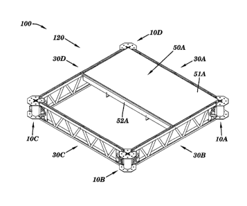
FIG. 7 depicts a section, or module", of a work platform support system 100 as
constructed. Note that four hubs 10A, 10B, 10C, 10D are interconnected with
four joists 30A,
30B, 30C, 30D. FIG. 7 shows a work platform support system 100 that is square
in plan. It
should be apparent to one skilled in the art, that other shapes and
configurations can be made.
By varying the lengths of joists 30, for example, other shapes can be made.
For example, a work
platform support system 100 that is rectangular can be constructed. Also, by
attaching joists 30
to various openings 13, 14 of the hub 10, various angles at which the joists
30 interconnect with
the hubs 10 can be achieved. For example, a work platform support system 100
that is triangular
in plan (not shown) may be constructed. Thus, by changing joist 30 lengths
(See e.g., FIGs.
19A-19D) and/or changing the angle(s) at which the joists 30 extend from the
hubs 10, virtually
any shape and size work platform support system 100 may be constructed..
Further, different
shape, size, and configuration of work platform support system 100 can be
joined and abutted
CA 02561444 2006-09-28
WO 2005/096725
PCT/US2005/010165
13
with each other, so that the work platform design is virtually completely
customizable. This
adaptability of the work platform support system 100 provides a convenient way
to gain access
to virtually any shape work area required in construction.
FIGs. 8A, 8B, and 8C depict various views, and close-up views of the
interconnection
between a middle support deck joist 52 and the joist 30. The middle support
deck joist 52
provides added support to support platforms 50 (see e.g., FIG. 9) and may span
between two
joists 30. At either end of the middle support deck joist 52 is a pin 53 which
communicates with
a corresponding hole 54 on the upper portion of the joist 30. For example,
FIG. 8B depicts an
exploded view of the interconnection, wherein pin 53 will go in hole 54A. In
this manner,
movement (both lateral and axial) of the middle support deck joist 52 is
minimized.
FIG.9 shows the embodiment of support system 100 from FIG. 7 wherein a
platform 50A
has been placed on the support system 100 thus transforming the support system
100 into a work
platform system 120. The platform 50A rests, in this embodiment, on the middle
support deck
joist 52A and on the joists 30A, 30B, 30D. The edges of the platform 50A may
rest on the top of
the middle support deck joist 52 and the angle iron 39A, 39B on the top of the
applicable joists
30A, 30B, 30D. The configuration of the top of the middle support deck joist
52 and the angle
iron 39A, 39B is such that vertical and horizontal movement of the platform
50A is avoided.
The work platform 50 typically is sized to be a 4' x 8' piece of material. The
work platform 50A
may include a wood panel 51A, for example. Suitable work platform 50 may be
made from
metal (e.g., steel, aluminum, etc.), wood, plastic, composite, or other
suitable materials.
Similarly, the work platform 50 may be made of items that are solid,
corrugated, [gated, smooth,
or other suitable configurations. For example, the work platform 50 may be
wood sheeting,
plywood, roof decking material, metal on a frame, grating, steel sheeting, and
the like. Thus,
after placing a first work platform 50A on the work platform support system
100, an installer
may continue in this manner and place additional multiple work platforms 50A,
50B, such as
CA 02561444 2006-09-28
WO 2005/096725
PCT/US2005/010165
14
shown in FIG. 10, so that the entire support system 100 covered with wood
platforms 51A, 51B
so that a complete work platform system 120 is created.
FIGs. 11A, 11B, and 11C show various close-up views of an additional, optional
feature
that may be provide as part of a work platform system 120. A deck retainer
plate 60 may be
placed over the spacing between the multiple work platforms 50. The deck
retainer plate 60 may
include a plurality of holes 62 so that a plurality of deck retainer bolts 61
may adhere the deck
retainer plate 60 to the joist 30. The deck retainer plate 60 is one way in
which to adhere work
platforms 50 to the support system 100.
As FIGs. 12 and 13 depict, there is virtually no limit as to the size and
shape of the
support system 100 and work platform system 120 that can be made with the
present invention.
FIGs. 12 and 13 show top and bottom perspective views, respectively, of one
large rectangular
embodiment of a support system 100 and work platform system 120.
As stated above, one deficiency of numerous existing work platforms are their
inability
to be installed in situ and also their inability to be relocated, extended, or
removed, while a
portion of the work platform is already installed in place. The present
invention overcomes this
deficiency. That is, the invention allows for a worker, or workers, to add on
additional sections
of support system 100 while this worker(s) is physically on an existing,
installed portion of
support system 100. That is the worker(s) can extend, relocate, or remove
support system 100
with only the need of hand tools. No mechanical tools, hoists, cranes, or
other equipment is
required to add to, subtract from, or relocate the support system 100. This
advantage, thus,
offers savings in labor, time, and equipment.
For as FIGs. 14 through 18 depict the gradual articulation of just one section
of work
support system 100 into place. This can be readily accomplished by one, or
two, workers by
simply placing sequentially an additional joist 30D off of an existing hub
10A. Then a "new"
hub 10D is connected to the first joist 30D. A second additional joist 30E is
connected to the
hub 30D. Further, another hub 10E and joist 30F are connected so that the
final joist 30F is
CA 02561444 2006-09-28
WO 2005/096725
PCT/US2005/010165
connected back to an existing hub 10B. In this manner, a worker(s) can install
a new section of
support system 100 (e.g., made up of "new" hubs 10D, 10E and "new" joists 30D,
30E, 30F) off
of an existing section of support system 100 (e.g., made up of inter alia hubs
10Q, 10B, 10C and
joists 30A, 30B). The worker(s) can install new, or relocate, sections of
support system 100,
5 while the worker remains on existing sections of work platform 50. That
is, additional lift
equipment, machinery is not required to install, relocate, or remove the
additional support
system 100 sections. Further, the installing worker(s) need not extend beyond
the existing
installed support system 100 or, they need only extend barely beyond the
system 100. This
allows the present invention to be safer than existing systems available,
during installation,
10 relocation, tear down, and movement. For example, as shown in FIG. 14,
the installer(s) can be
on the existing work platforms 50A, 50B, 50C, 50D when relocating, or
installing, the next
section(s) of the invention.
As FIGs. 15 through 17 clearly show via the motion arrows "M", that by a
combination
of rotation of the new joists 30D, 30E, 30F and new hubs 10D, 10E, that the
new section of work
15 support system 100 is able to move and rotate into its final requisite
location. That is, the
supports system 100 articulates into place. Further, the articulation can be
initiated and stopped
(and even reversed) by an installer(s) while the installer(s) remains on the
pre-existing support
system 100. Although not shown, additional supplemental devices to aid in the
articulation (e.g.,
motors, hand tools, mechanical tools, hydraulics, etc.) can be used.
FIG. 18 shows a new section of support system 100 articulated into place,
prior to the
installation of support platform(s) 50 and other pieces, as discussed supra
(See e.g., FIGS. 8A,
8B, 8C, 9, 10, 11A, 11B, 11C, 12). The removal of a portion of the support
system 100 can
essentially be done by reversing the aforementioned steps.
Although the present invention, as discussed, may be installed, and extended,
via the
aforementioned articulation capability, it should be apparent that this method
of use is not the
only method available. For example, in lieu of articulating the various
modules, or sections, of
CA 02561444 2011-09-14
72037-169
16
support system 100 from already installed section of support system 100, the
installation may be done, essentially, "in the air". That is, the system 100
may be
erected and connected together "in the air", in a piece-by-piece order via the
use of
multiple pieces of lifting, or hoisting, equipment. Alternatively, the hubs 10
and
joists 30 may be preassembled on the ground, or at a remote location, and then
moved and hoisted as a pre-assembled module into the desired location
underneath
a structure.
With reference to the teachings herein, including at least Figures 6A, 9
and 14-18, it is apparent that at least one of the joists is to be connected
with at least
one of the hubs using a pin to provide free rotation of the at least one joist
with
respect to the at least one hub about the pin. Moreover, it is apparent that
the free
rotation is restricted by at least one of: i) an additional pin that is to be
located
proximate a perimeter of the at least one hub; and ii) at least a portion of a
work
platform when the plafform is positioned with respect to the hubs and the
joists in the
final position.
FIGS. 19A, 19B, 19C, 19D show various embodiments of a joist 30 and
hub 10 configuration. For example, FIG. 19D shows a "standard" length joist
30A
(e.g., 8 foot nominal length) with two hubs 10A, 10B. This "standard" length
joist 30A
could be termed a "6/6 unit". FIG. 19C shows two joists 30A, 30B of equal
length
connected to hubs 10A, 10B, 10C. The joists 30A, 30B in FIG. 19C, being half
the
length, each of the length of the joist 30A in FIG. 19D, may be termed a "3/6
unit" in
that they are half the length of the aforementioned "6/6 unit". Similarly, two
unequal
length joists 30A, 30B are depicted in FIG. 19B, and can be termed a "2/6
unit" and a
"4/6 unit", respectively. This is because the "2/6 unit" is approximately one
third the
length of a "standard" "6/6 unit" joist as shown in FIG. 19D, as is the "4/6
unit" is
approximately two thirds the length of the "6/6 unit". The same system is
shown in
FIG. 19A, wherein the first joist 30A is termed a "1/6 unit" and the second
joist 30B is
termed a "5/6 unit". As stated above, by using different lengths of joist 30,
and by
extending joists 30 from hubs 10 at different angles, one can obtain a nearly
infinite
variety of configurations and footprints of the support systems 100. This
CA 02561444 2011-09-14
. 72037-169
16a
variety, for example, allows the installer to set up the support system 100
around
various obstacles (e.g., columns, piers, abutments, etc.) and structures. The
variety
allows the installer to create numerous shapes to the work platform system 120
beyond just a rectangle.
FIGS. 20A and 20B depict the plan view of just two embodiments of the
invention. In these figures it can be seen that the work platform support
system 100
is capable of various horizontal alignments. For example, FIG. 20A shows 8
foot
length joists 30 interconnected with
CA 02561444 2006-09-28
WO 2005/096725
PCT/US2005/010165
17
a plurality of hubs 10. Due to spacing between the pin 40 and hub 10, some
flexibility is
provided in the system 100 so that the system 100 can be curved, or "racked",
in the horizontal
direction. This can help allow the system 100 to be installed around
structures. FIG. 20B
depicts a system 100 that is angled. For example, the joists 30C connected to
hub 10C can be
shorter than joists 30B connected to hub 10B. Joists 30B, in turn, are shorter
than joists 30A,
which are connected to hub 10A. In this fashion, by using joists 30A, 30B, 30C
of different
length and/or altering the angle at which a joist 30 is connected to a hub 10,
systems 100 that are
angled, as in FIG. 20B can be configured. Similarly, this allows the system
100 to be installed,
for example, around various impediments, structures, and the like.
FIGS. 21A through 22C show various connection details as to how a railing
system can
be attached to the present invention. FIGs. 21A, 21B and 21C show the
interconnection between
a railing standard 85 and the hub 10. The railing standard 85 is typically
elongate an includes a
first flange 86A, and a second flange 86B extending therefrom for connection
to the hub 10. The
first flange 86A has a hole in it, as does the second flange 86B. By leading
the pin 40 through
the upper flange 86A, then through holes 13 in the upper element 11 down
through the lower
flange 86B, and then through the holes 14 in the lower element 12 an installer
is able to attach
the railing standard 85 to the hub 10 of the support system 100. The pin 40
may includes various
devices, such as roll pins 42 and a holding loop 43. In this manner, a
plurality of railing
standards 85 may be attached to a plurality of hubs 10, creating a railing
system around the work
platform system 120 so as to meet the regulations promulgated by OSHA.
FIGs. 22A, 22B, 22C depict various views of a railing standard 85 and its
interconnection
with a railing 88. The railing 88 can be a variety of materials, such as
chain, cable, line, and the
like. For example, the railing 88 may be galvanized aircraft cable. The
railing standard 85
includes a plurality of holes 87. As the exploded view in FIG. 22B shows, a J-
bolt 89 may be
used with a nut 84 to attach the railing 88 to the railing standard 85. By
attaching a plurality of
railings 88 to the plurality of railing standards 85 a railing system that
meets the OSHA
CA 02561444 2006-09-28
WO 2005/096725
PCT/US2005/010165
18
regulations is made. For example, an additional railing 88 may be added at the
midpoint of the
railing standard 85. In other embodiments, the railing standards 85 can also
be used to erect a
work enclosure system. For example, tarps, sheeting, or the like could be
attached to the railing
standards 85 to enclose the work area for painting, demolition, asbestos or
lead paint abatement,
and similar activities where the workers do not want any escape of fumes,
paint, hazardous
materials, debris, etc. from the work area.
FIG. 23 shows an elevation sectional view of one embodiment wherein a support
system
100 and work platform system 120 are attached, via a suspension connector 80,
to a structure 90.
The structure 90 in this embodiment is a bridge 90. On the underside of the
bridge 90 are a
plurality of beams 92. A series of suspension connectors 80, in this
embodiment high strength
chains, are attached to several of the beams 92 via structure attachment
device 82, in this
embodiment standard beam clamps. At the perimeter of the work platform system
120 are a
plurality of railing standards 85, thereby creating a railing system around
the work platform
system 120. The plurality of chains 80 are attached to various hubs 10 in the
support system
100 thereby providing structural connection to the bridge 90. In this manner,
a work platform
system 120 and support system 100 can be fully suspended from a suitable
structure 90. Note
that each hub 10 does not necessarily require a suspension connector 80 to be
connected to the
structure 90. For example, there is no suspension connector 80 connecting hub
10X to beam
92X. This may be because hub 10A does not line up underneath beam 92X, or
other suitable
suspension point, and thus, using a chain 80 in that location is either not
possible, or not
desirable.
The suspension connector 80 may be any suitable support mechanism that can
support
both the work platform system 120, and all its ancillary dead loads, plus any
intended live load
that is placed upon the work platform system 120. In fact, the work platform
system 120 may
support its own weight plus at least four times the intended live load that is
to be placed on the
work platform system 120. Similarly, the suspension connector 80 is also
suitable to support its
CA 02561444 2006-09-28
WO 2005/096725
PCT/US2005/010165
19
own weight plus at least four times the intended live load placed on it. The
suspension
connector 80 may be a high-strength chain, cable, or the like. For example,
one suitable
suspension connector 80 is 3/8", grade 100, heat-treated alloy chain.
The suspension connector 80 is attached to a beam clamp 82 which is further
attached to
a plurality of elements 92 on the underside of a structure 90. The structure
90 may be a bridge,
viaduct, ceiling structure of a building, or the like. Similarly, the elements
92 which the
suspension connector 80 are attached to may be beams, joists, or any other
suitable structural
element of the structure 90. Instead of beam clamps 82, other suitable
structure attachment
devices 82 may be used.
FIGs. 24A, 24B, 25A, 25B all depict various views of the interconnection
between the
suspension connector 80 (e.g., chain, cable, etc.) and the hub 10. In the
embodiment shown, a
free end of the chain 80 (i.e., end distal to structure 90) is placed through
the center opening area
19 of the top element 11 of the hub 10. The chain 80 is then slid over and in
to one of the four
slots 17 (e.g., 17A). Once the chain 80 is place within slot 17A, a chain
retainer pin 200 is
placed in the adjacent transverse slot 18A so that the chain 80 kept retained
in the distal end of
slot 17A. The chain 80 and slot 17A are sized and configured so that upon
proper placement of
the keeper pin 200 with in the transverse slot 18A, the chain 80 is
effectively locked to the hub
10 and is unable to slip, vertically or horizontally, from its position in
17A. This locking system
effectively fixes the hub 10 to the chain 80. As an added safety check, a zip
tie 201 may be
placed between a hole 202 in the chain retainer pin 200 and an adjacent link
in the chain 80.
This further provides a visual aid to the installer to ensure that the chain
retainer pin 200 has
been installed.
An alternative device for connecting a suspension connector 80 to the work
platform
support system 100 is a an auxiliary suspender mounting bracket 300. The
auxiliary mounting
bracket 300 is typically used when a particular hub 10 can not be accessed for
connection with a
suspension connector 80. As the various FIGS. 26A, 26B, 26C, and 26D depict,
one
CA 02561444 2006-09-28
WO 2005/096725
PCT/US2005/010165
embodiment of the auxiliary suspender mounting bracket 300 includes two
opposing and parallel
flanges 303. Spanning the flanges 303 is an interconnecting tube 304 and a
base plate 302.
Through the base plate 302 are a plurality of mounting holes 305. The
auxiliary suspender
mounting bracket 300 can be used in lieu of, or in addition to, the hub 10 for
a suspension point.
5 The bracket 300 allows a suspension connector 80 to be connected to the
system 100 at locations
other than a hub 10.
For example, FIG. 27 depicts a scenario that may typically be encountered when
installing a work platform system 120. Note that FIG. 27 is not drawn to
scale. One or more
obstructions 95A may be located on the underside of the structure 90, or
between the structure
10 90 and the work platform system 120. These obstruction(s) 95A may be man-
made, or natural.
For example, the obstructions 95A may be concrete beams, box-beams,
inadequately sized
framework, ductwork, lighting, finished surfaces, and the like. The
obstructions 95A are such
that a particular hub 10B is not practical, or possible, as a connecting point
for the system 120 to
a suspension connector 80. In this case, one or more auxiliary suspender
mounting brackets 300
15 may be attached to a joist 30. High strength bolts (not shown) may be
passed through the
mounting holes 305 and then through holes on an upper element 32 and connected
to bolts below
the upper element 32. (See for similar connection detail the connection of
plate 60 in FIG. 11B).
The suspension connector 80 (e.g., chain) may be connected, via a beam clamp
82, to a beam 92
that is on the underside of the structure 90.
20 As
shown in FIG. 27, obstruction 95B is directly vertically over hub 10B, thereby
rendering hub 10B inadequate for a suspension point. Thus, a bracket 300 can
be attached to a
joist 30 adjacent to hub 10B, thereby allowing a suspension connector 80 to
get proper
attachment to a nearby beam 92. The angle, 43.. between the suspension
connector 80 and
vertical, denoted by V, allows for the suspension connector 80 to be either
non-vertical, or
slightly off of vertical.
CA 02561444 2006-09-28
WO 2005/096725
PCT/US2005/010165
21
FIGS. 28A, 28B, and 28C show elevation views of various embodiments wherein
the
vertical flexibility of the present invention is apparent. For example, FIG.
28A shows a portion
of a work platform system 120 suspended from the non-flat underside of a
structure 90 (e.g.,
arched bridge). The suspension connector 80 and other connection details are
not shown for
ease of illustration. There is flexibility, due to the design, in the
interconnections between hub
and joist 30. This flexibility allows for some bendability in the vertical
direction (See e.g.,
FIG. 28A). This allows the system 120, for example, to parallel, or "mirror",
the underside of a
curved, arched bridge.
Alternatively, should the curvature of the supporting structure 90 be even
greater, a
10 configuration such as shown in FIG. 28B can be installed. That is
multiple portions of the
system 120 are not co-planar, but rather stepped, or tiered. If required,
various suspension
connectors 80 may be installed of such length so that multiple hubs 10A, 10B
may be installed to
the same suspension connector 80. As discussed above, the suspension connector
80 may be
connected to a slot 17 of the upper hub 10A, then passed through the bottom
opening 23 of the
upper hub 10A and then connected also to a slot 17 of the lower hub 10B (See
e.g., FIGs. 24A,
24B).
As FIG. 28C shows another configuration of the present invention is the
capability to
install the system 120 in a multi-level configuration. For example, where work
perhaps needs to
be done on a vertical structure 99 (e.g., bridge pier), at least two systems
120A, 120B may be
installed. Similar to the connection scenario used in FIG. 28B (above),
suspension connector 80
can, again, be of suitable length so as to pass from hubs 10A on the upper
system 120 on to, and
also connect up to, the hubs 10B on the lower system 120. In this manner,
multiple levels of
system 120 may be installed in a vertical orientation.
CA 02561444 2006-09-28
WO 2005/096725
PCT/US2005/010165
22
Load Testing:
The present invention is capable of supporting its own weight and at least
four times the
intended live load applied, or transmitted, upon the work platform system 120.
Various load
tests were conducted on the present invention. See e.g., Figure 26.
For example, one uniform load test was conducted on a 8 foot x 8 foot module
of a work
platform system 120. In this load test, a two (2) 4' x 8' sheets of 3/4" BB
OES Plyform decking
served as the platform 50. The platform 50 (i.e., Plyform) was installed as
discussed above. The
work platform system 120 included standard hubs 10, joists 30, supports 52,
and the like, as
discussed above. One of the two sheets of Plyform was uniformly loaded with a
plurality of
steel plates. Each plate was '/2" x 12" x30", and weighed 50 pounds. Twelve
(12) plates were
arranged per layer on the platform 50. A total of 256 plates were added,
producing a total live
load of 12,800 pounds, or 400 PSF (i.e., pounds per square foot). Further, the
Plyform platform
50 was thoroughly soaked with water while the full weight of the plates on it.
The test was
witnessed and there was no failure of the Plyform after being loaded for over
twenty four hours.
In conclusion, by using 3/4" BB OES Plyform as the platform 50 in the present
invention, when
supported on all four sides, the work platform system 120 is capable of
supporting a uniform
load of 100 PSF at a 4:1 safety factor.
Another load test was conducted on the invention.
In this second load test, a nominal 8 foot x 8 foot module of a work platform
system 120 was
erected. The four hubs 10 of this module were supported off the floor and
secured to resist
uplift. Then, two additional 8 foot x 8 foot work platform system 120 modules,
or "grids", were
assembled from one side of the original, supported module. This resulted in a
16 foot cantilever,
which simulates a scenario that might be encountered during erection of the
work platform
system 120. The work platform system 120 included standard hubs 10, joists 30,
supports 52,
and the like, as discussed above. One extreme corner of the cantilever was
loaded with weight to
simulate a load on a cantilever. A 1,000 weight with a 30" x 30" footprint was
placed on the
cantilevered corner. Additional 50 pound weights were added, producing a total
live load on the
CA 02561444 2006-09-28
WO 2005/096725
PCT/US2005/010165
23
corner of 2,200 pounds. The test was witnessed and there was no failure of the
work platform
system 120 and the maximum deflection at the hub 10 at the loaded corner was
6.5 inches. In
conclusion, in a 16 foot cantilever configuration, the present invention is
capable of supporting a
load of 550 pounds with a 4:1 safety factor.
A third load test that was conducted, and witnessed, on an embodiment of the
present
invention, entailed the live loading of a 16 foot span with 45 PSF x 4 Safety
Factor (i.e., 180
_
PSF). In this test, as depicted in FIG. 29, two joists 30A, 30B and three hubs
10A, 10B, 10C
were connected to form a 16 foot span. The span was then lifted via chains
80A, 80B connected
to the two outer hubs 10A, 10C. The chains 80A, 80B were connected, in turn,
to cables,
hydraulic cylinders, and fixed framing 500. As FIG. 29 indicates weight (i.e.,
22,835 pounds),
simulating an intended live load plus a factor of safety of four, were
suspended along lengths of
the joists 30A, 30B. Strips of plywood approximately 1 foot wide were clamped
to either side of
the joists 30A, 30B in to simulate a portion of the platform 50. The structure
(i.e., hubs 10, joists
30) was suspended with the aforementioned weight without failure. The test was
repeated a
second time, resulting in no failure.
A fourth load test conducted, and witnessed, on a portion of the present
invention
entailed a chain load test. In this test, a chain 80 was attached to a hub 10.
The chain 80, which
was a Grade 100 chain, was connected to one of the slots 17 of the hub 10,
similar to the
methods discussed above. The chain 80 and hub 10 assembly then was setup on a
hydraulic test
stand wherein a 30.6 Kip load was applied to the chain 80. There was no
failure of either the
hub 10 or chain 80. In conclusion, a typical hub 10 and chain 80 can withstand
at least a 7.4 Kip
load with a 4:1 factor of safety.
Thus, depending on spacing of the suspension connectors 80 that attach to the
work
platform system 120, various loading capabilities are created with the present
invention. If the
suspension connectors 80 are spaced in a 8 foot x 8 foot grid configuration,
the system 120 can
be termed a heavy duty support system that can support 75 PSF. If the
suspension connectors 80
CA 02561444 2006-09-28
WO 2005/096725 PCT/US2005/010165
24
are spaced at a 8 foot x 16 foot grid, the system 120 can be termed a medium
duty support
system that can support 50 PSF. Similarly, if the suspension connectors 80 are
spaced at 16 foot
x 16 foot grid, the system 120 can be termed a light duty support system that
can support 25
PSF.
The foregoing description of the present invention has been presented for
purposes of
illustration and description. It is not intended to be exhaustive or to limit
the invention to the
precise form disclosed or to the materials in which the form may be embodied,
and many
modifications and variations are possible in light of the above teaching.