Note: Descriptions are shown in the official language in which they were submitted.
CA 02561843 2006-09-29
WO 2005/097308 PCT/IB2004/051643
1
A HOMOGENISER FOR THE CONTINUOUS TREATMENT OF FLUIDS AT
VERY HIGH PRESSURE.
TECHNICAL FIELD AND BACKGROUND ART.
The present invention relates to a homogenises for the
continuous treatment of fluids at very high pressure.
Said apparatus, consisting of a plunger pump and of one or
more homogenising valves installed in series on the
delivery manifold, is applied in sectors such as the food,
pharmaceuticals, cosmetics, and chemical industries and is
used more generally for cell breakage treatment of fluids,
that is to say for biological products such as vaccines,
therapeutic substances and enzymatic and diagnostic
preparations.
The objective of all cell breakage techniques, using
predetermined apparatuses and/or chemical substances, is
to achieve productive cell disaggregation, that is to say.
which destroys any polluting cells, and at the same time
is able to liberate any subcellular substances useful for
subsequent production processes.
The use of a high pressure homogenises, which is normal in
mechanical cell breakage techniques, takes advantage of
the forced passage from a high pressure zone to a low
pressure zone, causing said controlled cellular
disaggregation of the fluid treated, using an adjustable
valve, commonly known as a homogenising valve, applied on
the plunger pump delivery side to generate the pressure
CA 02561843 2006-09-29
WO 2005/097308 PCT/IB2004/051643
2
required.
PR99A000045 by the same Applicant describes a pump for the
treatment of fluids at high pressure comprising a
reciprocating plunger in a compression chamber from a
fluid intake position to a fluid delivery position; a
block for each plunger, connecting the pumping chamber to
the intake and delivery valves housed in lateral
containers fixed to the block. Each block comprises two
half-parts or plates clamped together and having internal
grooves to house an internal manifold which connects the
pumping chamber and the intake and delivery valves.
The prior art comprises various different types of pumps
and therefore homogenisers able to operate at pressures
which range from around 500 bar to a maximum of 1500.bar.
Studies of said apparatuses have focused on a gradual
increase in the operating pressure.
Over the years such homogenisers have evolved to provide a
continuous increase in the operating pressures, focusing
on both the search for a type and configuration of
internal pipes eliminating all variations in cross-
section, intersection between holes and internal edges,
and on the search for special materials characterised by
greater resistance to the stresses to which the pipes and
in particular their intersections are subjected.
Initial studies allowed the development of increasingly
high operating pressures, up to a maximum of 1500 bar, but
research on the quality of the materials was abandoned on
CA 02561843 2006-09-29
WO 2005/097308 PCT/IB2004/051643
3
account of the impact that they would have had on the
final cost of the machine, limiting its commercial scope.
By means of computational fluid simulations followed by
laboratory tests, the Applicant analysed the assembly
consisting of the compression chamber, intake pipe and
delivery pipe, the pump and the homogenising valve which
together form a high pressure homogenises.
The Applicant's studies and experiments allowed the
identification of the geometrical set up and the technical
measures to be applied to the type of machine previously
described in order to obtain a prototype able to operate
at pressure values that are almost tripled.
DISCLOSURE OF THE INVENTIONE.
The aim of the present invention is to provide a
homogenises with a configuration which allows it to reach
pressures of up to 4000 bar, the materials used to
construct the part subject to the processed fluid pressure
being the same.
Another aim of the present invention is to provide a
homogenises able to operate at up to 4000 bar without
increasing its production costs for the maker and
maintenance costs for the end user.
Said aims are fulfilled by the machine disclosed, as
described in the claims herein.
In particular, the homogenises consists of a pump part
comprising at least one reciprocating plunger in a
compression chamber between a fluid intake position and a
CA 02561843 2006-09-29
WO 2005/097308 PCT/IB2004/051643
4
fluid delivery position; a block for each plunger,
connecting the compression chamber to the intake and
delivery valves housed in containers preferably having a
cylindrical shape connected to the upper and lower parts
of the block by removable connecting systems such as stud
bolts; an internal manifold connecting the compression
chamber to the intake and delivery valves, the homogeniser
being characterised in that, close to the manifold, the
plunger has a dynamic self-energising seal system acting
on its cylindrical surface, and in that upstream and
downstream of each valve, and downstream of the manifold
where the manifold intersects with the compression
chamber, and generally in the connections between the
various component parts of the assembly, there are static
seal systems consisting of an anti-extrusion ring in which
a self-energising seal with the appropriate geometry and
profile is inserted.
The delivery valve units, if more than one, there always
being the same number as the plungers, are connected to
one another by a delivery manifold which receives the flow
of pressurised liquid from each compression chamber.
Similarly, the equivalent intake. valve units, if more than
one, are connected to one another by an intake manifold,
and there may be a support flange for each intake valve
unit inserted between them.
BEST MODE FOR CARRYING OUT THE INVENTION.
This and other characteristics are more clearly
CA 02561843 2006-09-29
WO 2005/097308 PCT/IB2004/051643
illustrated in the description which follows, with
reference to the accompanying drawing, which illustrate a
preferred embodiment without limiting the scope of
application, and in which:
5 - Figure 1 is a side view and cross-section at mid length
of the pump part of the homogenises;
- Figure 2 is a side view and enlarged cross-section at
mid length of the guide chamber for the single-acting
reciprocating plunger;
- Figure 3 is a side view and enlarged cross-section at
mid length of the manifold connecting the compression
chamber and the valves;
- Figure 4 is a side view and enlarged cross-section at
mid length of a non-return delivery valve.
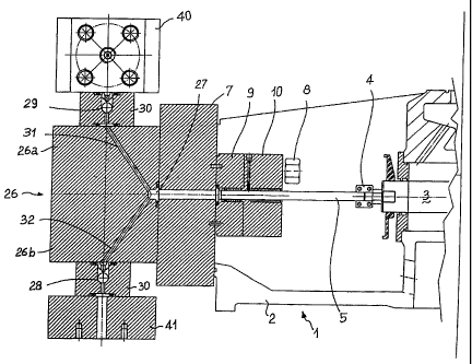
With reference to the accompanying drawings, the numeral 1
denotes as a whole a homogenises whose body 2 houses a
cross-head guide piston 3, driven in a substantially known
way, to the end of which a clamp 4 fixes a reciprocating
plunger 5 in a compression chamber or cylinder 6.
The plunger 5 is preferably made of a ceramic material
such as pure silicon nitride Si3N4.
The compression chamber 6 is formed inside a first block 7
to which stud bolts 8 fix a housing flange 9 and a locking
flange 10, the latter both preferably cylindrical and
between them forming a guide chamber 11 for the plunger 5
coaxial with the compression chamber 6 (Figure 2).
To prevent problems with the coaxial alignment between the
CA 02561843 2006-09-29
WO 2005/097308 PCT/IB2004/051643
6
compression chamber 6 and the guide chamber Z1 for the
plunger 5, and at the same time to facilitate assembly in
sequence on the block 7 first of the housing flange 9 then
the locking flange 10, the block 7 and the housing flange
9 have, on their surfaces which face one another, a
plurality of cylindrical connecting and centring pins 12,
whilst the locking flange 10 has, on the surface facing
the housing flange 9 a projection 13 having the shape of a
truncated cylinder designed to fit into a recess in the
surface of the housing flange 9.
Inside the locking flange 10 there is a seat 14, formed by
a widening of the cross-section of the guide chamber 11
hole, for housing a guide bushing 15 for the plunger 5,
made of self-lubricating plastic material, preferably
PEEK, and having one end 15a in contact with the widening
of the cross-section of the guide chamber 11 hole and the
opposite end 15b clamped by an elastic stop ring 16. Said
guide bushing 15 is preferably characterised by two or
more longitudinal cuts designed to reduce the contact
surface between the bushing 15 and the plunger 5 to limit
friction and allow evacuation of the lubricating liquid
used from a lubricating liquid feed pipe 17, present on
the locking flange 10 and preferably angled so that it is
perpendicular to. a horizontal plane passing through the
axis of the guide chamber 11 and parallel with the surface
of the locking flange 10 in contact with the housing
flange 9.
CA 02561843 2006-09-29
WO 2005/097308 PCT/IB2004/051643
7
Said lubricating pipe 17, supplied with water or another
type of liquid or emulsion, has one end 17a opening into
the plunger 5 guide chamber 11 and the opposite end 17b
terminating on the side wall of the locking flange 10.
Inside the housing flange 9, along the hole forming the
guide chamber 11, there is a first widening of the cross-
section 18 and a second widening of the cross-section 19,
separated from one another by a shoulder 20.
The first widening of the cross-section 18 involves the
insertion of a first dynamic seal unit 21 acting on the
surface of the reciprocating plunger 5, having a first
self-energising seal 22, preferably shaped so that it has
a single sealing lip and preferably made of a combination
of plastic materials such as high molecular weight PE and
PEEK, and fitted with an energising ring made of an
elastomer.
The first self-energising seal and a bearing assembly 23
face one another and are respectively closed upstream of
the first self-energising seal 22 by the shoulder 20 and
downstream of the bearing assembly 23 by the projection 13
on the locking flange 10. The projection 13 is used to
centre the PEEK bushing 15 relative to the housing flange
9.
The bearing assembly 23 is made of special non-galling
stainless steel, preferably Nitronic 60, and is coaxial
with and alongside the first self-energising seal 22 and
equipped with a system for extraction from its housing
CA 02561843 2006-09-29
WO 2005/097308 PCT/IB2004/051643
8
such as a suitably sized thread.
The second widening of the cross-section 19 houses a
second static seal unit 24 having a second self-energising
seal 25 (with dimensions and geometry allowing containment
of the very high pressures and preferably made of
polyurethane with Shore hardness 90-98), blocked upstream
of it by the surface of the block 7 and downstream of it
by the shoulder 20. The seal 25 does not make contact with
the plunger 5 and is designed to contain the pressurised
fluid between the block 7 and the chamber 6; it may also
be fitted with an external anti-extrusion ring 39.
The numeral 26 denotes a block consisting of two half
parts or plates 26a and 26b rigidly clamped to one another
by fixing means, preferably stud bolts not illustrated in
Figure 1.
The insides of the two plates 26a and 26b have been
machined to make grooves in them designed to house an
internal manifold 27, preferably having a hemispherical
shape, connecting the compression chamber 6 and a non-
return intake valve 28 and a non-return delivery valve 29
housed in containers 30 inserted between the central
blocks 26 and respectively the delivery manifold 40 and
the lower support flanges 41.
The block 26 may also consist of a single piece, directly
worked with a machine tool to create the channels 31 and
32 and the manifold hole 27 opposite the rear surface of
the block 26.
CA 02561843 2006-09-29
WO 2005/097308 PCT/IB2004/051643
9
The non-return intake valve 28 is connected to the
internal manifold 27 by the channel 31 which forms an
intake pipe and the non-return delivery valve 29 is
connected to the internal manifold 27 by the channel 32
which forms a delivery pipe.
The intake pipe and delivery pipe are arranged in such a
way that they are specular with one another relative to a
horizontal plane passing through the axis of the pumping
chamber 6 and set at an angle a to the normal to said
horizontal plane which varies from 45 to 62 degrees,
preferably 56 degrees.
Advantageously, the internal surfaces of the manifold 27
and of the intake and delivery pipes 31 and 32, exposed to
the pressure of the fluid, are treated by polishing,
radiusing of any edges on the intersections of concurrent
holes, micro shot peening and electropolishing.
For each non-return valve 28, 29, hollows are made close
to the upper and lower surfaces of the valve containers
30, respectively a first hollow 33 upstream of the non-
return valve and a second hollow 34 downstream of it
(Figure 4).
Said hollows 33, 34 are designed to accommodate a third
static seal unit 35 having an anti-extrusion ring 36,
preferably a circular ring with a rectangular cross-
section, inside which a third self-energising seal 37 is
fitted.
Said third static seal unit 35 is also inserted, by means
CA 02561843 2006-09-29
WO 2005/097308 PCT/IB2004/051643
of a third hollow 38, close to the internal manifold 27,
more precisely at the intersection between the manifold
and the compression chamber 6 (Figure 3).
The third static seal unit 35 has one end closed by the
5 block 7 and the opposite end contained in a widening of
the cross-section of the internal manifold 27.
Each anti-extrusion ring 36 is shaped in such a way as to
create an interference fit with the height of the
respective hollow 33, 34, 38, preferably by 0.1 mm, so
10 that, during assembly, the ring forms a mechanical seal on
the hollow and at the same time guarantees correct self-
energising seal 37 preloading.
The numeral 40 denotes a delivery manifold connecting the
two or more delivery valve 29 units, whilst 41 denotes a
support flange for the intake valve 28 unit for each
plunger connected to the pump intake manifold.