Note: Descriptions are shown in the official language in which they were submitted.
CA 02562023 2012-05-03
LONG TRAVEL HIGH CAPACITY FRICTION DRAFT GEAR ASSEMBLY
Field of the Invention
The present invention relates, in general, to friction-type draft gear
assemblies
used on railway cars to provide slack and to absorb shock loads encountered by
such railway
cars and, more particularly, this invention relates to a housing and friction
clutch mechanism
for use in a draft gear assembly having a longer travel capability and which
is capable of
reducing unwanted reaction force spikes, producing a smoother ride of the
railway vehicle,
and consequently increasing the overall efficiency of the draft gear.
Background of the Invention
Draft gear assemblies which utilize friction-type clutch mechanisms to absorb
heat energy generated during service have been in widespread use on railway
cars for several
years prior to the present invention, as is generally well known in the
railway art. These draft
gear assemblies are disposed within an elongated opening located in the center
sill member of
the railway car along the longitudinal axis thereof and behind the shank, or
innermost end, of
the railway car's coupling mechanism.
In this position, these friction clutch type draft gear assemblies will absorb
at
least a relatively large portion of both the buff and draft forces generated
during service.
Such buff and draft forces encountered by such railway car are usually being
applied in an
alternating manner to the center sill member during normal car operation on
the track.
A representative teaching of such prior art type friction clutch draft gear
assemblies can be found, for example, in U.S. Patent Numbers 2,916,163;
3,178,036;
3,447,693; 4,576,295; 4,645,187 and 4,735,328. Most, if not all, of these
prior art type draft
gear assemblies either have been or still are being utilized in the railway
industry prior to the
development of the present invention. Furthermore, except for U.S. Patent
Numbers
4,576,295 and 4,735,328, each of the remaining above-identified patents is
owned by the
assignee of the present invention.
It is quite well recognized, by those persons who are skilled in the friction
clutch type draft gear assembly design art, that these draft gear assemblies
must be provided
with the capability of maintaining at least a certain minimum shock absorbing
capacity both
during making up a train consist and in-track service. Such minimum capacity
has been
specified by the Association of American Railroads (AAR). For example,
friction clutch type
draft gear assemblies have a specified absolute minimum capacity rating of at
least 36,000
foot pounds. Any draft gear assembly with a capacity rating which is
determined to be below
1
WO 2005/100120 CA 02562023 2006-09-27PCT/US2005/011710
36,000 pounds will not receive approval from the AAR for service on any
railroad car which
may be used in interchange.
It is, likewise, important to note that the heat energy absorbing action of
the
friction clutch mechanism must enable this minimum capacity rating to be
readily achieved
without exceeding a specified maximum 500,000 pound reaction force, or
pressure, being
exerted on the center sill member of the railway car during both such make-up
and operation
of such train consist. It has been found that such maximum reaction pressure
is required to
enable these high energy shocks to be readily absorbed without upsetting the
end of the
coupling member shank and/or damaging other critical car components and/or the
lading that
) is being transported by such railway cars.
In order for the manufacturers of such friction clutch type draft gear
assemblies to meet the requirements of the railroad industry, with the ever
increasing load
carrying capacity of their modem day railroad cars, it has become of extreme
importance to
enhance the overall rated capacity of the friction-type draft gear assemblies
as much as
possible. This higher capacity rating being found necessary in order to
minimize any damage
to such cars and/or the lading due to the increased forces being exerted on
the center sill
member of the cars by the heavier loads such cars are now carrying.
U.S. Patent Number 5,590,797, owned by the assignee of the present invention
and hereby incorporated by reference thereto, relates to a friction clutch
mechanism for a
) high capacity draft gear assembly having a higher capacity rating as
discussed above. The
friction clutch mechanism in this patent improves upon the prior friction
clutch mechanisms
by modifying the wedge shoe members. Specifically, in the ('797) patent, the
wedge shoe
members have a Brinell Hardness of between 429 and 495 and an upper surface
which is
tapered from a point disposed inwardly from a tapered outer surface inwardly
toward and at
an acute angle relative to a longitudinal axis of the friction clutch
mechanism at an angle of
between 46.5 and 48.5 . The ('797) patent also teaches that it is
advantageous to include
brass inserts in various plate components of the friction clutch mechanism to
provide a
requisite amount of lubrication necessary to prevent detrimental sticking of
the friction clutch
mechanism after closure of the friction clutch draft gear assembly and during
a release cycle
D thereof.
While the above discussed design resulted in an improved friction clutch draft
gear assembly than those previously in use, it was determined that this
particular design does
not satisfy the requirements as defined in AAR Specification M-901-G. It was
determined
during testing of Super Mark 50's, with rusted friction packs, assembled with
H-911 brass
2
WO 2005/100120 CA 02562023 2006-09-27 PCT/US2005/011710
inserts, that the units tested had reaction force spikes higher than 500K.
This resulted in
hammer capacities of less than 36,000 ft/lbs. When tested on the test track,
the same super
Mark 50 reached the 500K reaction force levels well before the 5-MPH
requirement for a G
specification draft gear. Thus, a need exists in the art for a draft gear
assembly that meets the
standards as defined in AAR Specification M-901-G.
Additionally, it is now known that certain rail systems require a draft gear
having an extended travel distance of about 4.75 inches in order to meet their
requirements.
However, draft gear presently in use must fit within a 24.625 inch pocket and
have a travel distance of only 3.25 inches.
Objects of the Invention
It is, therefore, one of the primary objects of the present invention to
provide
an improved friction-type clutch mechanism which can be utilized to
significantly enhance
the capacity rating of a friction-type draft gear assembly to be used on a
railway car to absorb
buff and draft loads during service having a longer travel distance while
fitting in a 24.625
inch pocket.
Yet another object of the present invention is to provide a friction clutch
mechanism for use in a draft gear assembly which is capable of reducing
unwanted reaction
force spikes.
Still anotlner object of the present invention is to provide a friction draft
gear
assembly which produces a smoother ride of the railway vehicle.
A farther object of the present invention is to provide a friction draft gear
assembly which increases the overall efficiency of the draft gear.
Another object of the present invention is to provide a friction draft gear
assembly which is an all steel design and non-hydraulic which results in a
reduction in
production costs in terms of material and assembly time.
In addition to the objects and advantages listed above, various other objects
and advantages of the friction clutch mechanism of the draft gear assembly
disclosed herein
will become more readily apparent to persons skilled in the relevant art from
a reading of the
detailed description section of this document. The other objects and
advantages will become
particularly apparent when the detailed description is considered along with
the drawings and
claims presented herein_
SUMMARY OF THE INVENTION
Briefly, and in accordance with the forgoing objects, the invention comprises
an improved draft gear assembly having a housing member capable of fitting
into a 24.625
3
WO 2005/100120 CA 02562023 2006-09-27
PCT/US2005/011710
inch pocket while allowing a 4.75 inch travel. In the open end of the housing
there is a
friction clutch mechanism for absorbing heat energy in a friction clutch type
draft gear
assembly which is used. in a railway car. The friction clutch mechanism
includes a pair of
outer stationary plate members. Each of the pair of outer stationary plate
members has an
inner and an outer surface. The outer surface is engageable with a respective
radially opposed
portion of an inner surface of a draft gear housing member adjacent an open
end of such
housing member. The friction clutch mechanism further includes a pair of
movable plate
members. Each of the movable plate members has at least a predetermined
portion of an
outer surface thereof frictionally engageable with a respective inner surface
of the pair of
outer stationary plate members for absorbing at least a first portion of heat
energy generated
during closure of the friction clutch type draft gear assembly. A pair of
inner stationary plate
members are provided in the friction clutch mechanism. Each of the inner
stationary plate
members has an outer surface thereof frictionally engageable with at least a
portion of a
respective inner surface of the pair of movable plate members for absorbing at
least a second
portion of such heat energy generated during closure of the friction clutch
type draft gear
assembly. An inner surface of each of the inner stationary plate members is
tapered at a first
predetermined angle. A pair of wedge shoe members are provided. Each of the
wedge shoe
members includes a tapered outer surface frictionally engageable with a
respective inner
surface of the tapered stationary plate members for absorbing a third portion
of heat energy
generated during closure of such friction clutch type draft gear assembly. The
wedge shoe
members further include an upper surface which is tapered from a point
disposed inwardly
from the tapered outer surface inwardly toward and at an acute angle relative
to a longitudinal
axis of the friction clutch mechanism. The tapered upper surface is tapered at
an angle of
approximately 49.0 -50 .0 . The wedge shoe members also include a bottom
surface which is
tapered from a point disposed inwardly from the tapered outer surface inwardly
toward and at
an acute angle relative perpendicularly to the longitudinal axis of the
friction clutch
mechanism. A center -wedge member is provided which includes a pair of
correspondingly
tapered surfaces frictionally engageable with an upper tapered surface of a
respective one of
the pair of wedge shoe members for absorbing at least a fourth portion of such
heat energy
generated during closure of such friction clutch type draft gear assembly. The
pair of tapered
surfaces of the center wedge is tapered at an angle of between about 49.00-
50.00 .
A high capacity friction clutch type draft gear assembly for absorbing both
buff and draft loads being applied to a center sill member of a railway car
during make-up of
a train consist and in-track operation of such train consist including a
compressible
4
WO 2005/100120 CA 02562023 2006-09-27PCT/US2005/011710
cushioning element disposed adjacent a closed end of a housing member, a
friction clutch
mechanism as described above disposed at least partially within an open end of
the draft gear
housing member and a spring seat disposed intermediate such compressible
cushioning
element and such friction clutch mechanism.
BRIEF DESCRIPTION OF THE FIGURE
Figure 1 is a layout of the high capacity friction clutch type draft gear
assembly which illustrates a prior art type housing in which the friction
clutch is constructed
according to a presently preferred embodiment of the invention.
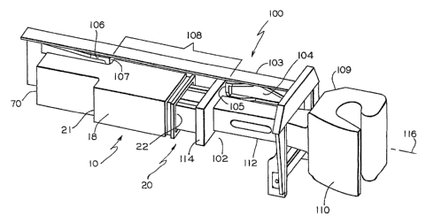
Figure 2 is a perspective view of the high capacity friction clutch type draft
gear assembly illustrated in Figure 1 but which illustrates a housing, having
the required
increased travel capability, for use with the friction clutch shown in Figure
1 that is
constructed according to a presently preferred embodiment of the invention.
Figures 3-6 are graphs illustrating reaction force (solid) in (kips) and
displacement (dashed) in (inches) at time in (sec) and speed in (Mph).
Figures 7-10 are graphs illustrating reaction force (solid) in (kips) at
displacement in (inches) and speed in (Mph).
DETAILED DESCRIPTION OF THE INVENTION
Now reference is made to the drawing figures which illustrates an improved
friction clutch mechanism, generally designated 20, best illustrated in Figure
1, for absorbing
heat energy in a friction clutch type draft gear assembly generally designated
10 which is
used in a railway car (not shown). This heat energy, as is quite well known in
the art, is
generated during the make-up of a train consist and during the movements of
such train
consist over a track structure.
The friction clutch mechanism 20 comprises a pair of outer stationary plate
members 12. Each of the pair of outer stationary plate members has an inner
surface 13 and
an outer surface 14. The outer surface 14 is engageable with a respective
radially opposed
portion of an inner surface 16 of a draft gear housing member 18 adjacent an
open end 22 of
such housing member 18.
The friction clutch mechanism 20 further includes a pair of movable plate
members 38. Each of the movable plate members 38 has at least a predetermined
portion of
an outer surface 40 thereof frictionally engageable with a respective inner
surface 13 of the
pair of outer stationary plate members 12 for absorbing at least a first
portion of heat energy
generated during closure of the friction clutch type draft gear assembly 10.
Each of the
5
WO 2005/100120 CA 02562023 2006-09-27PCT/US2005/011710
movable plate members 38 are generally rectangular in shape and the outer
surface 40 is
disposed substantially parallel to the inner surface 13 of outer stationary
plate members 12.
A pair of inner stationary plate members 44 are provided in the friction
clutch
mechanism 20. Each of the inner stationary plate members 44 has an outer
surface 46 thereof
frictionally engageable with at least a portion of a respective inner surface
39 of such pair of
movable plate members 38 for absorbing at least a second portion of such heat
energy
generated during closure of the friction clutch type draft gear assembly 10.
An inner surface
48 of each of the inner stationary plate members 44 is tapered at a first
predetermined angle.
The first predetermined angle of the inner surface 48 of the pair of inner
stationary plate members 44 is approximately 4.5 .
The friction clutch mechanism 20 further includes a pair of wedge shoe
members 54. Each of the wedge shoe members 54 includes a tapered outer surface
56
frictionally engageable with a respective inner surface 48 of the tapered
stationary plate
members 44 for absorbing a third portion of heat energy generated during
closure of such
friction clutch type draft gear assembly 10. The wedge shoe members 54 further
include an
upper surface 58 which is tapered from a point disposed inwardly from the
tapered outer
surface 56 inwardly toward and at an acute angle relative to a longitudinal
axis of the friction
clutch mechanism 20. The tapered upper surface is tapered at an angle of
approximately
49.0 -50.0 , preferably at an angle of 49.5 .
The wedge shoe members 54 also include a bottom surface 60 which is
tapered from a point disposed inwardly from the tapered outer surface 56
inwardly toward
and at an acute angle relative perpendicularly to the longitudinal axis of the
friction clutch
mechanism.
Also included in the friction clutch mechanism is a center wedge member 66.
The center wedge member includes a pair of correspondingly tapered surfaces 68
frictionally
engageable with an upper tapered surface 58 of a respective one of such pair
of wedge shoe
members 54 for absorbing at least a fourth portion of such heat energy
generated during
closure of such friction clutch type draft gear assembly 10. The pair of
tapered surfaces 68 of
the center wedge 54 is tapered at an angle of between about 49.0 -50.0 and
preferably at an
angle of 49.5 .
The inner surface 13 of each of the outer stationary plate members 12 of the
friction clutch mechanism 20 include a first elongated slot 24. This elongated
slot 24 will
have a generally arcuate shape in a plane disposed substantially at a right
angle to the
longitudinal axis of such first elongated slot 24. A first lubricating insert
member 28 is
6
WO 2005/100120 CA 02562023 2006-09-27PCT/US2005/011710
disposed within the first elongated slot 24 to prevent detrimental sticking of
the friction
clutch mechanism 20 after closure of such friction clutch type draft gear
assembly 10 and
during a release cycle thereof. The first lubricating insert members are
formed from a
mixture of a pre-selected lubricating metal and at least 2% graphite.
The outer surface 46 of each of the tapered plates 44 includes a second
elongated slot 52 having a generally arcuate shape in a plane disposed
substantially at a right
angle to the longitudinal axis of such second elongated slot 52. A second
lubricating insert
member 53 is disposed within the second elongated slot 52 of each of the
tapered plates 44 to
prevent detrimental sticking of the friction clutch mechanism 20 after closure
of such friction
clutch type draft gear assembly 10 and during a release cycle thereof. These
second
lubricating insert members 53 are also formed from a mixture of a pre-selected
lubricating
metal and at least 2% graphite.
The outer tapered surface 56 of each of said wedge shoe members 54 includes
a third elongated slot 62. This third elongated slot 62 has a generally
arcuate shape in a plane
disposed substantially at a right angle to the longitudinal axis of such third
elongated slot 62.
A third lubricating insert member 64 is located within each of these third
elongated slots 62
to prevent detrimental sticking of the friction clutch mechanism 20 after
closure of such
friction clutch type draft gear assembly 10 and during a release cycle
thereof. These third
lubricating insert members are also formed from a mixture of a pre-selected
lubricating metal
and at least 2% graphite.
The present invention, in a second aspect thereof, provides an improved higher
capacity rated friction clutch type draft gear assembly 10 for absorbing both
the buff and
draft loads which are applied to a center sill member, generally designated
100, of a railway
car (not shown) during the make-up of a train consist and the in-track
operation of such train
consist.
A front stop 104 and an axially opposed rear stop 106 are attached to each
side
member 103 of the center sill 100 and form a draft gear pocket 108 of a first
predetermined
length being 24.625 inches. A coupler arm 112 of a coupler 109 extends from a
typical
coupler knuckle 110 into the pocket 102. The coupler 109 is generally disposed
along the
longitudinal axis 116 of the center sill 100. The knuckle 110 of the coupler
arm 109 engages
a similar member protruding from a second railway car or locomotive to connect
the railway
cars for travel along railway tracks. A front coupler follower 114 is disposed
intermediate the
coupler arm 112 and the friction draft gear assembly 10 for evenly
transmitting the shock
from the coupler knuckle 110.
7
WO 2005/100120 CA 02562023 2006-09-27PCT/US2005/011710
In the presently preferred embodiment, such friction clutch type draft gear
assembly 10 includes a shaped housing member 18. The housing member 18 has an
end wall
70 for closing a first end thereof. The housing member 18 is open at a
radially opposed
second end 22 thereof. As can be seen in Figure 2, housing member 18 includes
ledges 21
which enable the housing 18 to be elongated while still fitting into a 24.625
inch pocket.
A compressible cushioning means 19 is disposed within a cavity of the
housing member 18 abutting at least a portion of an inner surface of the end
wall 70 disposed
at the first end of the housing member 18. The compressible cushioning means
19 extends
longitudinally from the first end. As shown in the U.S. Patents incorporated
by reference,
such compressible cushioning means 19 are well known in the art and normally
comprise a
plurality of springs in a variety of different arrangements, or a coil spring
in combination with
one or more resilient members such as a compressible rubber body, or a coil
spring in
combination with the hydraulic assembly.
The compressible cushioning means 19 stores at least a portion of energy
generated during a compressive force being applied to such friction clutch
type draft gear
assembly 10 and then releases the stored energy to restore the friction clutch
type draft gear
assembly 10 toward an open condition when such compressive force is either
reduced or
completely removed.
The friction clutch mechanism 20 is disposed at least partially within the
open
end 22 of the housing member 18. The inventive friction clutch mechanism 20 is
discussed
in detail above.
The friction clutch type draft gear assembly 10 further includes a spring seat
member 74 having at least a portion of a first surface 76 thereof abutting the
opposite end of
the compressible cushioning means 19 and a second surface 78 for engaging the
friction
clutch mechanism 20. The spring seat member 74 is mounted to move
longitudinally within
the housing 18 for respectively compressing and releasing the compressible
cushioning
means 19 during application and release of a force on the draft gear assembly
10.
The Mark 550 draft gear of the present invention is designed to meet the AAR
M-901-G specification. This draft gear is an all steel design similar to that
of a Mark 50-draft
gear. In the previous conducted tests on Super Mark 50 draft gears, with
rusted friction
packs, assembled with H-911 brass inserts, the units tested had reaction force
spikes higher
than 500,000 resulting in hammer capacities of less than 36,000 ft/lbs. When
tested on the
test track, the same Super Mark-50 reached the 500,000 reaction force levels
well before the
5-MPH requirement for a G specification draft gear. When brass inserts were
replaced with
8
CA 02562023 2012-05-03
inserts containing 2% graphite, the overall performance was reduced to levels
less than that
of a standard Mark 50. Installing the graphite inserts also eliminated the
high reaction force
spikes seen during the previous tests. As a result of the reduction in
capacity along with the
smoothing of the draft gear's closure curve led to a belief that additional
center wedge angle
described above might be necessary to meet the minimum test requirements for
the M-901-G
specification. During impact testing, it was also observed that the high
reaction force spikes
were eliminated and the gear's closure curve closely resembled that of an H-60
without the
initial effects of the hydraulic unit. It was determined that increasing the
center wedge shoe
angle by 2 degrees will increase the clamping force on the friction pack. It
was also
determined that applying inserts containing 2% graphite reduced any unwanted
reaction force
spikes. The combination of these two modifications increased the overall
performance of the
draft gear without adversely affecting its operation. Consequently, with
increasing the overall
efficiency, the draft gear will meet AAR M-901-G specifications. Additionally,
due to the
use of an all steel design and the elimination of the hydraulic means reduced
production costs
in terms of material and assembly time.
The invention has been described in such full, clear, concise and exact terms
so as to enable any person skilled in the art to which it pertains to make and
use the same. It
should be understood that variations, modifications, equivalents and
substitutions for
components of the specifically described embodiments of the invention may be
made by
those skilled in the art without departing from the scope of the invention as
set forth
in the appended claims.
9