Note: Descriptions are shown in the official language in which they were submitted.
CA 02562122 2006-10-04
WO 2005/097646 PCT/FI2005/050110
1
Method and apparatus for reeling control
The invention concerns a method and apparatus for controlling reeling used in
connection with the making of paper/board/an equivalent web-like material, in
which reeling a reefer is used, which comprises a reeling element, a reeling
core,
around which the web is reeled to form a reel, as well as elements for loading
the
reeling core and the reeling element against each other in order to bring
about a
reeling nip in between the reeling element and the reel.
The invention relates generally to the making of paper, tissue or board or
some
other equivalent web-like product and to the associated reeling. When
referring
hereinafter to a papermaking machine or to paper, such reference also includes
a
machine intended for making the above-mentioned products or the product to be
made by it.
The finished paper web of a papermaking machine or other device processing a
web-like product is reeled around a roll in a reefer located at the end of the
ma-
chine, which is called a reeling drum. The reel formed around the roll from
the
paper web of full width emerging from the machine is called a machine reel. In
the reeling device, that is, in the reefer, a reeling cylinder rotates at a
peripheral
speed equal to the speed of the paper web. The reeling cylinder is bearing-
mounted in the body of the reeling device with the aid of shafts located at
its ends.
At its one end the reeling cylinder is connected to a driving device, which
for its
part is in connection with the overall drive of the machine in such a way that
the
reeling cylinder's peripheral speed is equal to the speed of the completed
paper
web emerging from the machine. This type of reefer goes under the name of Pope
reefer. Besides the reeling cylinder, a reeling belt may also be used in the
reefer,
which belt is known from the applicant's FI-94231 patent.
CA 02562122 2006-10-04
WO 2005/097646 PCT/FI2005/050110
2
The finished web is collected on a reeling drum located at the reeling
station,
while the drum is loaded at the same time towards the reeling cylinder. The
reel-
ing drum may have its motional power with the aid of friction through the
paper
web from the reeling cylinder (a so-called peripherally driven Pope reefer) or
ac-
s cording to a solution in general use today, it can be provided with a drive,
whereby the reefer is called a centre-driven reefer.
When a sufficient quantity of paper web has accumulated on the reeling drum,
the
reel is dismounted from the surface of the reeling cylinder. The reel's
peripheral
speed will decrease as the reel is slowed down, and a bag will form in the web
before the reeling drum, which bag is guided with the aid of an airflow and
placed
around a new empty reeling drum brought to the reeling cylinder. The paper web
moving on to a full reeling drum will break off immediately and it starts
winding
around the new reeling drum. Other alternative ways are also used, and they de
pend on the basis weight of the paper, among other things.
In connection with the reeling, especially with today's high and constantly in-
creasing speeds, an over-pressure occurs in the inlet jaw between the web and
the
reeling cylinder, in consequence of which an excessive quantity of air will
pene-
trate in an undesirable manner between the reeling cylinder and the arriving
paper
web. This problem occurs especially in broad machines operating at high speeds
and it is especially harmful with paper grades poorly permeable to air (with
grades
calendered on line in particular).
The forming air bag, which is located just before the reeling nip between the
reel-
ing cylinder and the reel, makes air penetrate between the paper layers,
whereby
smaller air bags will form especially between the topmost layers. The phenome-
non is illustrated in the appended Figure 1B, which shows air bags b forming
in
the reel in spaces between the topmost paper layers P1, P2, P3, Pa. The air
can only
escape from the ends of the reel, whereby air will collect in the reel's
middle parts
in particular. This causes several various problems, such as folding,
looseness in
CA 02562122 2006-10-04
WO 2005/097646 PCT/FI2005/050110
3
the reel structure and various flaws in the paper quality. The phenomenon can
occur, for example, as a star pattern visible at the end of the reel. The
quality
problems resulting in this manner will for their part give rise to an
increasing
quantity of rejects in the production.
An attempt to solve the airbag problem is made, for example, by a solution pre-
sented in the printed patent specification FI 107327, wherein the reeling
cylinder
is grooved to conduct the air away in a controlled manner from the reeling
nip.
Another problem occurring in connection with reeling relates to cross-cutting
of
the paper web in connection with the reel change. Irrespective of the cross-
cutting
method used, the problem in connection with cross-cutting is the occurrence of
loose pieces of paper, that is, fodder, and their ending up inside the
material to be
reeled. If in connection with unreeling fodder drifts to the following process
stage,
typically in connection with the calendering on to rolls, then damages may
result,
which must be corrected at high costs. The calenderer's roll coatings in
particular
are easily damaged by the impact of superfluous particles.
According to the state of the art, attempts have been made to solve said
fodder
problem by leaving a sufficient quantity unused of the reel's final part in
connec-
tion with the unreeling. The idea is to make sure in this manner that no
fodder will
occur in the part of the reel intended for use. However, the consequence is a
loss
of material, since an unnecessarily large quantity of paper is often rejected
just to
be sure.
Of the problematic situations occurring with the reeler such a situation may
also
be mentioned, where at least a double folding has formed in the edge of the
paper
web or equivalent and such a double part begins assembling in the reel. As the
reel is growing, the nip will draw in this double area only, but not in the
other part
of the reel. The occurrence of a double edge may be caused, for example, by
flap-
ping of the edge, which may result from a too high running speed, profile prob-
CA 02562122 2006-10-04
WO 2005/097646 PCT/FI2005/050110
4
lems in the web, breaking of the edge or quality flaws occurring in connection
with the calendering, such as a sharp fold in the paper.
As the size of the roll is growing, a double edge will cause mechanical
tensions in
the reel. The mechanical tension is released when the paper layers in the reel
yield, and in this way a situation arises where the reel disintegrates.
Disintegration
may even take place explosively, whereby pieces weighing 0.5 - 5 kilos may
hurl
out of the disintegrating reel into the environment. The hurling reel pieces
cause a
hazardous situation for people nearby. They may also cause mechanical damages
to equipment nearby.
Furthermore, such a problematic situation occurs in connection with reeling,
where the paper web piles up or folds up on the reel bottom in connection with
the
reel change, and a situation where the web does not move on to the reel but
drifts
around the reeling cylinder or elsewhere near the reeler. In addition, the web
may
have split up in the machine direction before the reeling, and this will lead
to qual-
ity problems in the reeling. At times when the edges of a split web have over-
lapped, the split web is not necessarily detected by the state-of-the-art
devices
observing holes occurring in the web.
The invention aims at providing a method and device in connection with reeling
for significantly reducing the problems presented above.
The invention aims at providing a method and device in connection with reeling
for automatic detection of problematic situations occurnng in reeling.
The invention aims at providing a method and device in connection with reeling
for automatic correction of problematic situations occurnng in reeling.
The method according to the invention is characterised in that reeling is
monitored
by a detection apparatus, which automatically detects events differing from
nor-
CA 02562122 2006-10-04
WO 2005/097646 PCT/FI2005/050110
mal reeling.
The apparatus according to the invention for its part is characterised in that
the
apparatus comprises means for automatic detection of situations differing from
5 normal reeling.
According to the invention, the area in between the reeling cylinder and the
reel is
is observed by a measuring device in order to detect reeling errors, that is,
an air-
bag and/or loose pieces of paper and/or a double edge and/or piling up of the
web
and/or a split web. The observing is done by a detection apparatus comprising
a
monitoring device, preferably a camera or a distance-measuring laser, as well
as a
data processing unit, and various computer vision methods and related pattern
recognition methods are utilised in the observing.
When observing airbags occurring in the reeling area, the dimensions
permissible
for airbags are determined and when these are exceeded steps are taken in
order to
diminish the airbag. The measured information obtained from the apparatuses
for
airbag detection is used for controlling the airbag by controlling the reeling
pa-
rameters, such as the linear load, the web tension or the peripheral force.
Correspondingly, loose pieces of paper occurring in connection with the
reeling
are observed by the detection apparatus. The information on loose pieces of
paper
detected by the monitoring device according to the invention is supplied, for
ex-
ample, to a measuring unit used for determination of the reel size, which
registers
that place in the reel where fodder occurs. Based on this information, exact
infor-
mation is obtained on how big a part of the beginning of the reel has to be re-
jected.
For its part, detection of a double edge or a web split in the machine
direction by
the detection apparatus according to the invention results in an interruption
of the
reeling, until the fault has been corrected, or in a reel change. With the
apparatus
CA 02562122 2006-10-04
WO 2005/097646 PCT/FI2005/050110
6
according to the invention such a situation is also detected, where the web
does
not end up in the reel but starts winding around the reeling cylinder or
drifts to
some other wrong place. When this occurs, the reeling must be interrupted. An
interruption of the reeling results in a signal being given to the web-break
moni
toting, whereby the web will be run as reject from a suitable shutdown point.
With the automatic monitoring of the reeling area according to the invention
one
avoids the exhausting monitoring by human eyes of the reeling area, and
prompter
control or correction measures can also be taken when problems occur. For exam-
ple, when an airbag occurs, the dimensions of the forming airbag can automati-
cally be kept within permissible limits by using the feedback adjustment
accord
ing to the invention. Steps can be taken quickly to deal with other problems
no
ticed and the situation can be restored to normal. With papermaking machines,
better runnability and a higher running speed are hereby achieved, among other
things.
By using the method and apparatus according to the invention the quantity of
re
sulting rejects can be reduced significantly. In consequence of this, costs
savings
are achieved and the drawbacks caused by interruptions in the production are
re
duced.
The apparatus according to the invention for controlling reeling can be imple-
mented as a modular system, which can easily be installed as a retrofit even
in old
papermaking machines or finishing machines.
The method and apparatus according to the invention can be applied in all
reeling
devices used in papermaking, which are, for example, a papermaking ma
chine's/tissue-making machine's/board-making machine's continuously working
reeler, an intermediate reefer, a calender's in-reefer, a coating machine's
reefer
and a slitter's reeling part.
CA 02562122 2006-10-04
WO 2005/097646 PCT/FI2005/050110
7
The invention will be described in greater detail in the following by
referring to
the appended figures, in which:
Figure 1A illustrates airbags occurring in the reeling area and it presents a
first
way of measurement for observing the reeling area.
Figure 1 B presents airbags occurring in between paper layers.
Figure 2 shows another way of measurement for observing the reeling area.
Figure 3A shows a third way of measurement for observing the reeling area.
Figure 3B shows a picture taken by the third way of measurement during a
normal
reeling process.
Figure 3C shows a picture taken by the third way of measurement of an airbag
formed in connection with reeling.
Figure 4 shows a fourth way of measurement for observing the reeling area.
Figure SA shows a fifth way of measurement for observing the reeling area.
Figure SB shows a picture taken by the method of measurement according to Fig-
ure SA of a loose piece of paper ending up in the reeling area.
Figure 6 shows a sixth way of measurement for observing the reeling area.
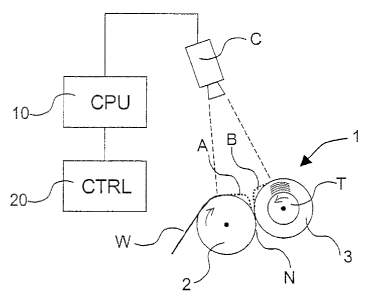
Figure 1A shows a first way of measurement for observing a reeling area. In
this
embodiment, the measured object is especially the detection of airbags
occurring
near the reeling nip. Figure 1A is a schematic view of a papermaking machine's
reeler 1 comprising a reeling element, preferably a reeling cylinder 2 and a
reeling
CA 02562122 2006-10-04
WO 2005/097646 PCT/FI2005/050110
g
core, such as a reeling drum T or a reel 3 formed around a reel core. The
paper
web W is guided through the reeling cylinder 2 on to the reel 3. An arrow
drawn
into the reeling cylinder 2 indicates the reeling cylinder's 2 direction of
rotation
and an arrow drawn into the reeling core T indicates the reeling core's T
direction
of rotation. Differing from this presentation, it is also possible as the
reeling ele-
ment to use the reeling wire presented in the applicant's FI-94231 patent.
In connection with reeling cylinder 2 beside the nip N an airbag A has formed,
and an airbag B has formed atop the reel 3 beside nip N. The reeling area is
ob-
served in order to detect airbags by an apparatus, which in this embodiment
com-
prises a camera C functioning as the monitoring device and connected to it in
data
communication connection a data processing unit 10. In Figure 1A, the area ob-
served by camera C is delimited by dashed lines. The area under observation is
chosen by adjusting the camera's characteristics (the focal distance, the
distance
between the camera and the target, zooming, etc.) in such a way that both
airbags
A, B will be visible in the pictures taken by the camera C. It is advantageous
to
illuminate the reeling area by a light source (not shown in Figure 1 A) and
the di-
rection of incidence of the light is chosen so that any abnormal phenomena ob-
served in the reeling area will show in a pronounced manner. When observing
airbags or other objects slightly raised from the web, the direction of light
inci-
dence is preferably adjusted to be almost in parallel with the web, whereby
the
shadows of observed objects will show as clearly as possible. Electromagnetic
radiation is used as the light source, preferably a source producing a visible
or an
invisible light.
The camera C for use in the different embodiments of the present invention may
be a line camera, digital camera, video camera or some other scanner suitable
for
computer vision applications and applicable to observation of a reeling area.
Camera C is a scanner detecting electromagnetic radiation, preferably visible
or
invisible light. From camera C the information is transmitted as a suitable
signal,
for example, as a video signal when using a video camera, to a data processing
CA 02562122 2006-10-04
WO 2005/097646 PCT/FI2005/050110
9
unit 10, which will determine the airbag's dimension or a sudden change of the
situation. The data processing unit 10 is a functional unit comprising the
processor
and memory capacity necessary for the invention. It may be a separate unit or
a
part of an available information system and it has the required data
transmission
connections with other systems, such as the monitoring systems of a
papermaking
machine.
From the data processing unit 10 the control information is transmitted to the
con-
trol unit 20 for reeling parameters used for controlling the reeling
parameters. The
control unit 20 for reeling parameters is a functional unit, which may be
imple-
mented, for example, as a part of a reeling control unit. Controlled reeling
pa-
rameters are, for example, one or more parameters from the following set of
con-
trol targets: linear load, web tension, peripheral force, profiling
electrostatic nip,
air pressure device, profiling nip roll or running speed.
Figure 2 shows another way of measurement for detecting airbags. In the em-
bodiment shown in Figure 2, the reeling area is observed by an apparatus
compris-
ing distance-measuring lasers L1, L2, L3, of which there are three in this
example,
but the number of which can also be different from the number presented here.
The distance-measuring lasers L,, L2, L3 give information on changes in the
reel
size at the point where the airbag occurs. The size of reel 3 is also
constantly ob-
served by a reference-measuring laser LK, which is directed at such a place,
where
airbags do not occur and which thus gives exact reference information on the
reel
size. The size of the airbag B formed on the reel is determined by subtracting
the
distance information given by the reference laser LR from the measurement
infor-
mation of lasers Ll, L2, L3. The measured distance information is taken to the
data
processing unit 10, which processes the information and which when required,
upon detecting an exceptional situation, gives a control signal to the control
unit
20 for reeling parameters.
Figure 3A shows a third way of measuring for observing a reeling area. Figure
3A
CA 02562122 2006-10-04
WO 2005/097646 PCT/FI2005/050110
shows an embodiment according to the invention, wherein the detecting
apparatus
comprises means (not shown) for bringing about one or more laser lines as well
as
one or more cameras C for picturing the laser line/lines. According to the
inven-
tion, the laser line 1i is directed at the reel surface in a transverse
direction and the
5 shape of the laser line 11 is observed on the picture taken by camera C.
When an
airbag occurs on the reel surface, a change can be seen in the picture taken
by
camera C by comparing it with a picture where no airbag is seen. In this
manner
information is obtained automatically about the occurrence of an airbag.
10 The shape of the airbag can be determined as different coordinate points,
whereby
measured points can be stored and descriptors can be drawn of the coordinates.
The resulting data can also be read by normal types of control room software,
and
real-time trends of the bag's shape can be displayed on the control room
display.
In this manner alarm limits can be established for the displayed data in such
a way
that as the airbag grows bigger than a certain established limit an alarm will
be
given to the operating staff, or the reeling parameters will be adjusted
automati-
cally. In an embodiment of this kind, no specific software or algorithms need
be
developed for the processing, but these can be procured as ready-for-use
products.
If it is desirable to monitor not only the length of the airbag but also its
width at a
certain place of the reel, a second laser line 12 can be set crosswise to the
former
laser line in the machine direction. In addition, Figure 3A shows a third
laser line
13, which is directed at the end of the reel and which can be pictured and
used for
measuring the size/thickness of the reel. Information relating to the reel
size can
be utilised, when wishing to store in a memory at which point of the reel the
air-
bag has occurred, and when possibly choosing not to use this part of the reel
later
in connection with the unreeling.
Figure 3B shows a picture taken by camera C on the laser line 1, in a
situation
where no airbag occurs. The laser line 11 is hereby of a straight shape.
Correspond-
ingly, in Figure 3C a picture has been taken, where an airbag occurs and the
shape
CA 02562122 2006-10-04
WO 2005/097646 PCT/FI2005/050110
11
of the laser line l, has changed. By having a programme compare these pictures
an
automatic airbag identification system is brought about.
Figure 4 shows a fourth way of measurement for observing a reeling area. Ac-
cording to this embodiment, a light pattern is directed at the reeling area to
be
observed and the light pattern is scanned by a camera. When the reeling
situation
changes, for example, upon emergence of an airbag, the shape of the light
pattern
will change and the change is detected optically.
The apparatus according to the fourth way of measurement comprises a light
source LS1, a camera C and a data processing unit 10, which is in connection
with
a control unit 20 for the reeling parameters. The light source LS, produces a
line
pattern P to the observed reeling area. Light source LS, produces
electromagnetic
radiation, preferably visible or invisible light. The line pattern P can be
produced,
for example, by a coherent laser light or by some other suitable light source.
The
line pattern P is preferably a regular line pattern, for example, a line grid,
such as
is shown in Figure 4, or some other line pattern, wherein any occurring
geometri-
cal changes can be clearly detected, which have occurred upon a change in the
web's geometry. The pictures are analysed in the data processing unit 10,
wherein
a reference picture is stored of line pattern P in a situation, where the
reeling situa-
lion is normal and the web is in an optimum state. The data processing unit 10
compares in real time the pictures taken of the reeling area with the
reference pic-
ture, and based on this comparison any changed situation will be detected. In
the
analysis of the line pattern methods of image processing and analysis known as
such are utilised. For example, when using a very dense line pattern, it is
possible
in the analysis to use analysing methods relating to the so-called Moire's
pattern.
Figure SA shows an embodiment according to the invention, wherein the reeling
area is observed from the input side of the in-reefer in order to detect loose
pieces
of paper, that is, fodder H. Figure SA shows an apparatus according to the
inven-
tion, which is used for monitoring the reeling area from the input side of the
nip of
CA 02562122 2006-10-04
WO 2005/097646 PCT/FI2005/050110
12
the in-reeler. Reeler 1 comprises similar parts as those described in
connection
with Figure 1 A. The detection apparatus comprises a camera C functioning as
the
monitoring device and a data processing unit 10. The monitoring device is used
to
measure changes occurring in the cross machine direction of the web, and the
pic-
ture area is set so that any loose pieces of paper about to drift through the
nip will
be detected. The monitoring devices used are, for example, one or more digital
cameras, and the camera uses a short shutter time (for example, 1/10 000).
When
the nip area is well illuminated, any loose pieces of paper moving in the area
will
stand out clearly and the obtained change information will be taken to the
moni-
toring apparatus. In the detection apparatus a reference picture is stored,
where the
nip area is trouble-free. The pictures taken during monitoring are compared
with
the reference picture, and any changes, which may have occurred in the area,
are
detected automatically with the aid of picture-analysing software known as
such.
Figure SB shows an example of a picture taken by a detection apparatus in
accor-
dance with the embodiment presented in Figure SA, which picture has been proc-
essed, for example, by an analysing programme and wherein a loose piece of pa-
per can be seen. When detecting deviations in the pictures, the current reel
size at
the moment of detection is stored and this information on the reel size is
stored. In
the following unreeling, this information can be utilised and the concerned
part of
the reel can be guided for removal of that part (as reject) from the reel,
where fod-
der was found to occur. Alternatively, the concerned part of the reel can be
run
slower during unreeling. Limit values can be established for the size of
deviations
in the picture area detected by the camera, whereby very small pieces of paper
may be overlooked, if desired. The limit value can be set, for example, by
defin-
ing a permissible number of pixels, where changes occur in the grey level, or
al-
ternatively by defining the duration of the occurring trouble pulse.
Figure 6 shows a sixth way of measurement according to the invention for obser-
vation of the reeling area. In this way of measurement, the reeling area is
observed
in order to recognise a double edge. The web W arriving at reeling cylinder 2
is
CA 02562122 2006-10-04
WO 2005/097646 PCT/FI2005/050110
13
lighted by a lighting device LS2 from one side of the web, in this example
from
below, and the lighted area is pictured by camera C from the opposite side of
the
web. The lighting device LSZ produces electromagnetic radiation, preferably
visi-
ble or invisible light. In the pictures taken by camera C, the area de
occurring at
the edge of web W, where the edge of the web has folded so that it is double,
is
detected due to the intensity, which is different from the rest of the web.
From
camera C the picture information is supplied to the data processing unit 10,
from
which information on the exceptional situation is supplied to the reefer's
control
unit 20, when required. With this method and apparatus it is also possible to
detect
other irregularities occurring in the web, such as holes or non-homogeneous
areas,
which can be seen in the pictures taken by camera C on account of their
different
intensity.
In the following, claims will be presented, but there is no intention to limit
the
invention solely to these claims.