Note: Descriptions are shown in the official language in which they were submitted.
CA 02562236 2012-02-03
1
CABLE ANCHOR BRACKET
TECHNICAL FIELD OF THE INVENTION
The present invention relates generally to guardrail
systems and, more particularly, to a cable anchor system.
BACKGROUND OF THE INVENTION
Guardrail systems are widely used along heavily
traveled roadways to enhance the safety of the roadway
and adjacent roadside. For example, end terminals are
utilized at the upstream end of guardrail systems to
dissipate impact energy from head-on collisions of
vehicles with the upstream end to prevent intense
deceleration of the vehicles. In addition, guardrail
systems are designed to contain and redirect vehicles
that impact the guardrails predominantly from the side.
One element that is utilized in guardrail systems to
address impacts along the side of the guardrail
downstream from the end terminal is a tension cable that
connects between the end terminal support post and the
guardrail. The
tension cable is designed to provide
tension strength during side impacts and to breakaway
during head-on impacts to avoid counteracting the
benefits of the impact absorbing end terminal.
CD, 02562236 2012-02-03
la
SUMMARY OF THE INVENTION
Certain exemplary embodiments can provide a guardrail
system, comprising: a guardrail; an end terminal coupled
to the guardrail; a support post for supporting the end
terminal; a cable anchor bracket coupled to the guardrail;
a cable extending between the support post and the cable
anchor bracket; the cable anchor bracket comprising: a
plate having an aperture formed therein; a plurality of
protrusions coupled to the plate and extending from a
plane containing the aperture, the plurality of
protrusions releasably engaging a plurality of apertures
formed in the guardrail; wherein the cable is coupled to
the support post at a first end and coupled to the
aperture of the plate at a second end, the cable
terminating at the aperture such that an extension of a
longitudinal axis of the cable from the second end forms
an acute angle with respect to a longitudinal axis of the
guardrail and approximately intersects a centroid of the
protrusions; and wherein a longitudinal axis extending
through the center of the aperture in a direction
substantially perpendicular to the plane having the
aperture is substantially perpendicular to the
longitudinal axis of the cable when the cable is coupled
to the plate having the aperture.
Certain exemplary embodiments can provide a guardrail
system, comprising: a guardrail; an end terminal coupled
to the guardrail; a support post for supporting the end
terminal; a cable anchor bracket coupled to an attachment
portion of the guardrail; a cable extending between the
support post and the cable anchor bracket; the cable
anchor bracket comprising: a flat plate defining a plane
CA 02562236 2012-02-03
lb
having an aperture formed therein; a plurality of
protrusions coupled to the flat plate and extending from
the plane containing the aperture, the plurality of
protrusions releasably engaging a plurality of apertures
formed in the attachment portion of the guardrail; and
wherein the cable is coupled to the support post at a
first end and coupled to the aperture of the flat plate at
a second end, a longitudinal axis of the cable
substantially aligning with the plane defined by the flat
plate having the aperture formed therein.
Certain exemplary embodiments can provide a cable
anchor bracket for coupling a cable to a guardrail,
comprising: a flat plate having an aperture formed
therein; a plurality of protrusions extending from a plane
containing the aperture, the protrusions configured to
releasably engage the guardrail; and wherein the aperture
of the plate is operable to receive one end of the cable,
wherein a longitudinal axis of the cable substantially
aligning with the plane defined by the plate having the
aperture formed therein.
Other embodiments provide a cable anchor system for
an end terminal includes a cable anchor bracket configured
to couple to a guardrail, in which the cable anchor
bracket includes a flat plate having an aperture formed
therein and a plurality of protrusions extending from a
plane containing the aperture. The protrusions are
configured to releasably engage the guardrail.
CA 02562236 2006-10-05
WO 2005/100694
PCT/US2005/011266
2
Technical advantages of particular embodiments of
the present invention include improved performance of the
connection between the tension cable and the guardrail by
improving the alignment between the tension cable and
anchor bracket. This is facilitated by an improved cable
anchor bracket that reduces the eccentricity of the
alignment between the cable and the guardrail. The cable
anchor bracket also reduces manufacturing cost.
Other technical advantages are readily apparent to
one skilled in the art from the following figures,
descriptions and claims. Moreover, while specific
advantages have been enumerated above, various
embodiments may include all, some or none of the
enumerated advantages.
BRIEF DESCRIPTION OF THE DRAWINGS
FIGURES 1 and 2 are plan and elevation views,
respectively, of a guardrail system according to one
embodiment of the present invention;
FIGURES 3A and 3B are perspective and elevation
views, respectively, illustrating the coupling of a cable
anchor bracket to a guardrail in accordance with one
embodiment of the present invention;
FIGURE 4 is an elevation view of a cable anchor
bracket according to one embodiment of the present
invention;
FIGURE 5 is an elevation view of a guardrail system
according to one embodiment of the present invention in
which the guardrail is a box beam; and
FIGURES 6A and 6B are perspective and elevation
views, respectively, illustrating the coupling of a cable
anchor bracket to a box beam in accordance with one
embodiment of the present invention.
CA 02562236 2012-02-03
3
DETAILED DESCRIPTION OF THE INVENTION
FIGURES 1 and 2 are plan and elevation views,
respectively, of a guardrail system 100 according to one
embodiment of the present invention. Guardrail system
100 may be installed adjacent a roadway to protect
vehicles, drivers and passengers from various obstacles
and hazards and prevent vehicles from leaving the roadway
during a traffic accident or other hazardous condition.
Guardrail systems incorporating aspects of the present
invention may be used in median strips or shoulders of
highways, roadways, or any suitable path that is likely
to encounter vehicular traffic. =
In the illustrated embodiment, guardrail system 100
includes a guardrail 102, an end terminal 104, a support
post 106, a cable anchor bracket 108, and a cable 110.
Guardrail 102 may be any suitable guardrail, such as
a w-beam (illustrated in FIGURES 1 and 2) or a box beam
(as illustrated in FIGURE 5), having any suitable length.
In the embodiment illustrated in FIGURES 1 and 2, an end
of guardrail 102 is supported by end terminal 104, which
may be any suitable end treatment. In the illustrated
embodiment, end terminal 104 resembles a guardratl
extruder terminal ("GET"), such as the ET-2000 and ET-
PLUS manufactured by Trinity Industries, Inc. An
example description of a GET is described in U.S. Pat.
No. 4,928,928 by Buth et al. The present invention
contemplates any suitable end terminal that has a
releasable anchor plate, such as a Sequential Kinking
Guardrail Terminal System ("SKGTS"), an Anchor Assembly
for Highway Guardrail End Terminal ("AAHGET"), a
CA 02562236 2006-10-05
WO 2005/100694
PCT/US2005/011266
4
Guardrail Cutting Terminal ("GCT"), and a Box Beam
Terminal.
Support post 106 functions to support end terminal
104 and/or guardrail 102. In the illustrated embodiment,
support post 106 is a breakaway support post formed from
a generally rectangular wood post; however, support post
106 may be any suitable support post formed from any
suitable material and having any suitable shape.
Cable anchor bracket 108 may be coupled to guardrail
102 in any suitable manner; however, it is envisioned
that cable anchor bracket 108 be releasably engaged with
guardrail 102 so that cable anchor bracket 108 may be
easily released from guardrail 102 during a head-on
collision of a vehicle with an end 105 of end terminal
104 to avoid possible jamming of the movement of end
terminal 104 and facilitate the safe and effective
kinetic energy reduction during the head-on collision.
In the illustrated embodiment, cable anchor bracket 108
is releasably coupled to guardrail 102 with a plurality
of protrusions 112, as described in greater detail below
in conjunction with FIGURES 3A and 3E.
According to the teachings of the present invention,
cable anchor bracket 108 provides an improved alignment
of cable 110 with guardrail 102 to provide improved
performance of the connection between cable 110 and
guardrail 102. As described in greater detail below,
eccentricities with respect to cable 110 and the
connection between cable anchor bracket 108 and guardrail
102 are reduced, thereby reducing moments resulting from
a collision of a vehicle with the side of guardrail 102.
A reduction in moments reduces the likelihood of "tear-
out" of protrusions 112 and strengthens the connection
between cable anchor bracket 108 and guardrail 102. The
CA 02562236 2006-10-05
WO 2005/100694
PCT/US2005/011266
connection between cable anchor bracket 108 and guardrail
102 is described in greater detail below in conjunction
with FIGURES 3A and 3B.
Cable 110 extends between support post 106 and cable
anchor bracket 108. Cable
110 may be any suitable
elongated element formed from any suitable material that
provides tension to guardrail system 100 during a
collision of a vehicle with a side of guardrail 102. A
general function of cable 110 during a collision may be
found in U.S. Pat. No. 4,928,928. In the
illustrated
embodiment, cable 110 forms an acute angle 111 with
respect to a longitudinal axis 109 of guardrail 102.
Acute angle 111 may be any suitable angle; however, in
one embodiment, acute angle 111 is between approximately
and 25 degrees. One end of cable 110 couples to a
lower portion of support post 106 in any suitable manner
and the other end of cable 110 couples to cable anchor
bracket 108 in any suitable manner. One
example of
coupling cable 110 to cable anchor bracket 108 is shown
and described below in conjunction with FIGURES 3A and
3B.
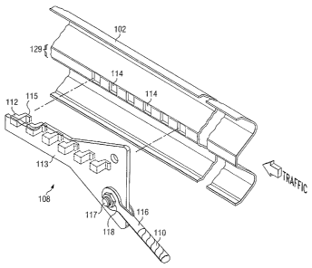
FIGURE 3A is a perspective view and FIGURE 3B is an
elevation view illustrating the coupling of cable 110 to
cable anchor bracket 108 and cable anchor bracket 108 to
guardrail 102 according to one embodiment of the
invention. In the
illustrated embodiment, cable anchor
bracket 108 is formed from a plate 113 having an aperture
119 formed therein and a plurality of protrusions 112
coupled to plate 113 and extending from a plane
containing aperture 119. Plate
113 is preferably a
single flat plate of structural steel with a thickness
between approximately 1/4 inches and 3/4 inches.
CA 02562236 2006-10-05
WO 2005/100694
PCT/US2005/011266
6
However, plate 113 may be formed from any suitable
material having any suitable thickness.
Aperture 119 is utilized to couple cable 110 to
cable anchor bracket 108 by any suitable method. In the
illustrated embodiment, a shackle 116 is utilized along
with a bolt 117 and a nut 118 to couple the end of cable
110 to plate 113. The use
of shackle 116 allows a
longitudinal axis 120 (FIGURE 33) of cable 110 to
substantially align with a plane containing plate 113.
For example, a plane running through the mid-thickness of
plate 113, as denoted by reference number 122,
substantially aligns with longitudinal axis 120.
Depending on the location of support post 106 (see FIGURE
1) and where cable 110 couples to support post 106,
longitudinal axis 120 may form a slight angle with a
plane containing plate 113. In addition, a longitudinal
axis 121 of aperture 119 (FIGURE 33) is substantially
perpendicular to longitudinal axis 120. This positioning
of cable 110 with respect to plate 113 results in an
eccentricity 123 with guardrail 102 that is less than
eccentricities of prior cable anchor systems. The
reduction in eccentricity reduces the moment on the
connection of protrusions 112 with guardrail 102, thereby
introducing less stress to the connection during a side
impact collision. Thus,
there is less chance for
"tearing-out" of protrusions 112 during a side impact
collision, which improves the performance of the
connection.
In the illustrated embodiment, protrusions 112
cooperate with a plurality of apertures 114 formed in
guardrail 102 in order to releasably couple cable anchor
bracket 108 to guardrail 102. In the
illustrated
embodiment, this is facilitated by a plurality of tabs
CA 02562236 2006-10-05
WO 2005/100694
PCT/US2005/011266
7
115 associated with respective protrusions 112 that "hook
on" respective apertures 114 formed in an attachment
portion 129 of guardrail 102. The tautness of cable 110
after installation ensures the correct positioning of
cable anchor bracket 108 in addition to keeping a snug
fit of protrusions 112 with apertures 114. Any suitable
number and arrangement of protrusions 112 may be utilized
within the teachings of the present invention. The
present invention also contemplates other suitable
coupling methods for cable anchor bracket 108 that
facilitate a releasable engagement.
FIGURE 4 is an elevation view illustrating another
advantage of cable anchor bracket 108 according to one
embodiment of the invention. As
described above in
conjunction with FIGURES 1 and 2, cable 110 forms acute
angle 111 with respect to the longitudinal axis 109 of
guardrail 102. As
illustrated by FIGURE 4, this
facilitates an extension 122 of longitudinal axis 120 of
cable 110 intersecting a line 130 extending through the
interior protrusions, as denoted by reference numeral
132, when viewed from a side elevation as in FIGURE 4.
In a particular embodiment, extension 122 may intersect a
centroid 124 of all of the protrusions 112. Interior
protrusions are defined by all of the protrusions 112
except the upstream-most protrusion(s) 112 and
downstream-most protrusion(s) 112.
This positioning of cable 110 with respect to plate
113 substantially reduces or eliminates eccentricities,
as denoted by eccentricity 126, that exists in prior
cable anchor systems, thereby reducing an additional
moment on the connection between cable anchor bracket 108
and guardrail 102. Eccentricity 126 results from the
positioning of prior cables (denoted by reference numeral
CA 02562236 2006-10-05
WO 2005/100694
PCT/US2005/011266
8
127) of prior cable anchor systems.
Eccentricity 126
causes additional stress on the connection between the
cable anchor bracket and the guardrail of prior guardrail
systems, thereby enhancing the possibility of failure of
the connection and minimizing the effectiveness of a
tension cable during a side impact with the guardrail.
Referring now to FIGURE 5, an elevation view of
guardrail system 100 according to another embodiment of
the present invention is illustrated in which the
guardrail is a box beam 500. In this
embodiment,
guardrail system 100 includes a cable anchor bracket 502
that couples to a bottom 503 of box beam 500. In the
illustrated embodiment, box beam 500 has an "open" cross-
section that resembles a C-section; however, box beam 500
may also have a "closed" cross-section.
Cable anchor bracket 502 may be coupled to bottom
503 of box beam 500 in any suitable manner; however, it
is envisioned that cable anchor bracket 502 be releasably
engaged with box beam 500 for reasons discussed above in
conjunction with cable anchor bracket 108. In the
illustrated embodiment, cable anchor bracket 502 is
releasably coupled to box beam 500 with a plurality of
protrusions 504, as described in greater detail below in
conjunction with FIGURES EA and 6B.
FIGURE EL is a perspective view and FIGURE 6B is an
elevation view illustrating the coupling of a cable 506
to cable anchor bracket 502 and cable anchor bracket 502
to box beam 500 according to one embodiment of the
invention. In the illustrated embodiment, cable anchor
bracket 502 is formed from a flange plate 508, a web
plate 510 having an aperture 512 formed therein, and a
plurality of protrusions 504 coupled to flange plate 508.
Flange plate 508 and web plate 510 are preferably single
CA 02562236 2006-10-05
WO 2005/100694
PCT/US2005/011266
9
flat plates of structural steel with a thickness between
approximately 1/4 inches and 3/4 inches. However, flange
plate 508 and web plate 510 may be formed from any
suitable material having any suitable thickness. In the
illustrated embodiment, web plate 510 extends
substantially perpendicular to flange plate 508; however,
web plate 510 may be angled with respect to flange plate
508 in some embodiments.
Aperture 512 is utilized to couple cable 506 to
cable anchor bracket 502 by any suitable method. In the
illustrated embodiment, a shackle 511 is utilized along
with a bolt 513 and a nut 515 to couple the end of cable
506 to web plate 510. The use of shackle 511 allows a
longitudinal axis 516 (FIGURE 6B) of cable 506 to
substantially align with web plate 510. Depending on the
location of support post 106 (see FIGURE 1) and where
cable 506 couples to support post 106, longitudinal axis
516 may form a slight angle with web plate 510.
In the illustrated embodiment, protrusions 504
cooperate with a plurality of apertures 518 formed in
bottom 503 of box beam 500 in order to releasably couple
cable anchor bracket 502 to box beam 500. In the
illustrated embodiment, this is facilitated by a
plurality of tabs 509 associated with respective
protrusions 504 that "hook on" respective apertures 518
formed in bottom 503 of box beam 500. The tautness of
cable 506 after installation ensures the correct
positioning of cable anchor bracket 502 in addition to
keeping a snug fit of protrusions 504 with apertures 518.
Any suitable number and arrangement of protrusions 504
may be utilized within the teachings of the present
invention. The present invention also contemplates other
CA 02562236 2006-10-05
WO 2005/100694
PCT/US2005/011266
suitable coupling methods for cable anchor bracket 502
that facilitate a releasable engagement.
Referring back to FIGURE 5, cable 506 forms an acute
angle 507 with respect to the longitudinal axis of box
beam 500. This
facilitates an extension 520 of
longitudinal axis 516 of cable 506 intersecting a line
extending through the interior protrusions, as denoted by
reference numeral 522. In a
particular embodiment,
extension 520 may intersect a centroid of all of the
protrusions 504.
Thus, an improved cable anchor bracket is disclosed
by the present invention that improves performance of the
connection of the cable anchor bracket with the guardrail
by reducing eccentricities associated therewith. Reduced
eccentricities result in reduced moments and reduced
stress at the connection, thereby increasing the strength
of the connection and ensuring that the anchor cable may
perform its function in an efficient and safe manner.
Although the present invention is described by
several embodiments, various changes and modifications
may be suggested to one skilled in the art. The present
invention intends to encompass such changes and
modifications as they fall within the scope of the
present appended claims.