Note: Descriptions are shown in the official language in which they were submitted.
CA 02562278 2006-10-06
WO 2005/100099 PCT/US2005/012635
BUMPER WITH NESTING ENERGY-ABSORBING END PIECE
CROSS-REFERENCE TO RELATED APPLICATIONS
[0001] This application claims benefit of provisional application Serial No.
60/561,737,
filed April 13, 2004, entitled BUMPER WITH NESTING ENERGY-ABSORBING
END PIECE, the entire contents of which are incorporated herein in their
entirety.
BACKGROUND
[0002] The present invention relates to vehicle bumper systems having energy
absorbers,
including energy-absorbing end pieces that nest against the bumper beam.
[0003] Modern vehicles have bumper systems that are both functional and
aesthetic.
Functionally, they must be able to withstand substantial impact requirements,
including
front and corner impact testing standards, such as those set by the insurance
and federal
agencies. Also, they must meet customer expectations concerning appearance. In
particular, many modern vehicles have an aerodynamic appearance, with sweeping
curved fronts, especially at vehicle corners. The vehicles are also compact in
design.
This results in conflicting requirements. On the one hand, the reinforcement
beam must
provide substantial strength for frontal impact, but must not interfere with
the sweeping
"rounded-off" corner designs on the vehicles. As a result, many beams have
their ends
modified, such as by attaching a separate component to an end of the beam to
provide a
mitered/angled cut on the front outer end (see U.S. patent 6,042,163, angled
front
surface 42 in Fig. 4). Other beams have ends that are miter cut, and then have
flat plates
welded onto the miter cut portion to form a sharply angled front outer
surface. However,
such processes are expensive, because cutting a high-strength beam is
expensive, and
also because weldingly attaching a secondary bracket is time consuming,
expensive, and
leads to inconsistencies, variables, and complications in the final
components.
[0004] Thus, a system having the aforementioned advantages and solving the
aforementioned problems is desired.
SUMMARY OF THE PRESENT INVENTION
[0005] In one aspect of the present invention, a bumper system includes a
tubular beam
having front and rear walls and horizontal walls connecting the front and rear
walls, with
CA 02562278 2006-10-06
WO 2005/100099 PCT/US2005/012635
an end of at least the front wall being removed to thus form forwardly-open
pockets in
the beam. An energy-absorbing end piece is nested into the pockets in each end
that
forms an energy-absorbing corner arrangement for corner impact.
[0006] In another aspect of the present invention, a bumper system includes a
tubular
beam having miter-cut ends that form forwardly-open pockets. Energy-absorbing
end
pieces are nested into each of the pockets to form energy-absorbing corner
arrangements
for corner impact. In narrower aspects, a center energy absorber is also
engaged with a
face of the beam, the center energy absorber and the end pieces having front
surfaces
that define a continuous curvilinear front support structure for fascia on the
vehicle. Also
in a narrower aspect, the end pieces include flanges that frictionally engage
the pockets
to retain the end pieces to the beam during assembly.
[0007] These and other aspects, objects, and features of the present invention
will be
understood and appreciated by those skilled in the art upon studying the
following
specification, claims, and appended drawings.
BRIEF DESCRIPTION OF DRAWINGS
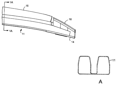
[0008] Fig. 1 is a top fragmentary view of the present bumper system;
[0009] Fig. 1A is a cross-sectional view of the "B" beam of Fig. 1;
[0010] Fig. 2 is an exploded perspective view of Fig. 1; and
[0011] Figs. 3-4 are perspective views of the energy-absorbing end pieces
shown in
Figs. 1-2.
DETAILED DESCRIPTION OF PREFERRED EMBODIMENTS
[0012] A bumper system 10 (Fig. 1) includes a high-strength metal B-shaped
beam 11
with miter-cut end sections 12, a front center energy absorber 15 against a
face of the
beam 11, and a pair of energy-absorbing end pieces 16 that nestingly engage
front outer
ends of the beam 11. By this arrangement, the bumper system 10 with energy
absorbers
15-16 forms an impact system capable of providing iinpact resistance as
required by
Federal Motor Vehicle Safety Standards of the U.S. government, yet at a
reduced cost.
In particular, the energy-absorbing end pieces 16 act as a low-cost and
lightweight
extension to the beam 11, and absorb energy so as to lessen intrusion and
decrease the
energy that is transmitted into the frame rails.
-2-
CA 02562278 2006-10-06
WO 2005/100099 PCT/US2005/012635
[0013] The illustrated beam 11 defines two tubes 11A and 11B. (It is
contemplated that
the present invention could also be used on other beam sections, such as a "D"
shaped
beam or box beam.) Each end section 12 is miter-cut to have an angled front on
its front
outer ends. This allows the beam 11 to better match the aerodynamic curved
shape of a
front of the vehicle to which it is attached without adversely affecting a
position of the
fascia which covers a front (or rear) of the vehicle. The remaining material
(i.e., the
four exposed horizontal walls that form the "B" beam) forms a pair of
forwardly and
laterally open pockets or channels 13 in the two tubes 11A and 11B of the beam
11. A
mounting bracket 14 is attached behind the end section 12 adjacent its outer
end. The
mounting bracket 14 includes a plate attached to the beam 11, such as by
welding, and
includes holes, apertures, or flanges configured for attachment to a vehicle
frame rail.
[0014] A center energy absorber 15 is positioned against a face of the beam
11. The
center energy absorber 15 can be any one of a variety of constructions, such
as an
injection-molded part with box-shaped energy-absorbing crush boxes, and/or
foam
blocks, and/or honeycomb-shaped components and/or hybrids thereof. The center
energy
absorber 15 defines a front surface that extends curvilinearly across a front
(or rear) of a
vehicle, and is useful for both absorbing energy and also supporting a fascia
on the
vehicle. Notably, a depth of the energy absorber 15 is not necessarily
uniform, but
instead is designed to provide the curvature around a front (or rear) of the
vehicle as
may be desired. For example, near outer ends of the center energy absorber 15,
there is
potentially an increasing curvature of its face surface.
[0015] The energy-absorbing end pieces 16 are injection-molded "honeycomb-
shaped"
components configured to be mated against each of the end sections 12. The end
pieces
16 each include two rearwardly-protruding lobes 17 shaped to nestingly fit
into the
pockets 13 and includes two inwardly-extending tongues 18 that fit partially
into an open
end of the tubes 1 1A and 11B. It is contemplated that the tongues 18 can be
eliminated
in some circumstances. A center flange 19 connects the upper and lower lobes
17 of the
energy absorber end piece 16, and upper and lower "J" flanges 20-21 extend
upwardly
and downwardly from the lobes 17, respectively, to define cavities that
matingly
frictionally engage the exposed walls on the end sections 12. The flanges 19-
21 can be
designed to provide friction for retaining the end pieces temporarily in place
until the
fascia is installed, or can include detent bumps or hooks that more securely
frictionally
-3-
CA 02562278 2006-10-06
WO 2005/100099 PCT/US2005/012635
engage the beam 11 for retaining them in place. The illustrated energy-
absorbing end
pieces 16 extend outboard of the beam 11 and include an outer portion that
abuts an
outer portion of the plate on the mounting bracket 14. A front surface of the
end pieces
16 forms a continuous surface with the front surface of the center energy
absorber 15, so
as to form a continuous support surface around the front (or rear) corner of
the vehicle
for supporting fascia thereon. The illustrated end pieces 16 are designed so
that they can
be molded using injection-molding dies that do not require cutouts, slides,
die pulls, or
other moving die parts that make the dies more complex and higher maintenance.
[0016] The end pieces 16 nestingly engage the end of the beam 11 due to both
the
tongues 18 and the lobes 17. This nested arrangement is stable on the beam 11,
such that
the arrangement is able to withstand significant corner impact forces, despite
the beam
11 terminating at the mounting bracket 14, and despite a lack of substantial
energy
absorber material extending outward from the mounting brackets 14. Notably, on
vehicles that include side rails on their frames that are located closer to an
outboard edge
of the vehicle, the present bumper system 10 has been found to be particularly
effective.
[0017] It is to be understood that variations and modifications can be made on
the
aforementioned structure without departing from the concepts of the present
invention,
and further it is to be understood that such concepts are intended to be
covered by the
following claims unless these claims by their language expressly state
otherwise.
-4-