Note: Descriptions are shown in the official language in which they were submitted.
CA 02562280 2006-10-06
WO 2005/106306 PCT/EP2005/004579
Spacer for coaxially sheathed fuel pipes
The present invention relates to a spacer, particularly for coaxially sheathed
fuel
pipes of an aircraft. The intermediate space obtained via the spacer is used
for
ventilation and drainage of leakage liquid and condensed water, particularly
for fuel
pipes in aircrafts, in which such coaxially sheathed fuel pipes are required
and/or
prescribed in the fuselage region.
Coaxially sheathed fuel lines comprise an internal line and an external line,
which
encloses the internal line. In order to ensure a uniform distance between
internal and
external pipes under all circumstances, spacers are necessary between the
internal
and external pipelines. Internal and external lines may be manufactured from
identical or different materials. These may be pipe, hose, or cable systems.
Currently, plastic spacers are disadvantageously used, which are fixed in a
slip-proof
way on the internal pipe using complex screw fasteners. This type of mounting
may
only be performed in a cumbersome way. The danger exists that damage to the
internal pipe will occur because of the high pre-tension force of the screw.
The
internal pipe may, for example, be dented by the high force. During the
mounting,
one must work with special care in order to avoid contact of the screw
fastener with
the external pipe. If contact with the screw occurs, the external pipe may be
damaged. In addition, multiple components (main body, screw, washer, nut) must
be
assembled during mounting, which is disadvantageous. Therefore, the greatest
care is
required during mounting, because of which mounting becomes complex.
New requirements for implementing special pipe diameters and especially small
spaces between internal and external pipe lines may not be implemented using
screw
fasteners because of the space required.
It is an object of the present invention to specify an improved spacer.
According to an exemplary embodiment of the present invention, a spacer for
pipes
is specified. The spacer comprises a closure, a pipe clamping structure, and
at least
one distance element. This at least one distance element is attached to the
pipe
clamping structure. The at least one closure is integrated into at least one
of the pipe
clamping structure and the at least one distance element.
CA 02562280 2006-10-06
WO 2005/106306 PCT/EP2005/004579
-2-
This exemplary embodiment of the present invention advantageously allows the
integration of the closure into the spacer. In this way, a loss of closure
elements
during mounting may be suppressed. Errors during assembly may also be avoided.
If
necessary, the mounting may even be performed by untrained personnel.
In contrast to known plastic spacers described above, errors may be avoided
during
mounting and time may be saved during assembly. The components necessary for
the
mounting are mounted on the part itself and present on location. Therefore, it
is no
longer possible to lose elements important for mounting without destroying the
part.
According to a fiu-ther exemplary embodiment of the present invention, the at
least
one distance element and a pipe form a unit. The at least one distance element
holds
the pipe at a defined distance in relation to a receiver. Through this
arrangement, a
permanently determined distance between the pipe and the receiver may be
produced, so that pipe and receiver do not touch.
According to a further advantageous exemplary embodiment of the present
invention, the arrangement of the at least one distance element and a first
pipe may
be designed in such a way that it is held centered in a second pipe. Through
the
sheathing of the first pipe by the second pipe, ventilation of the first pipe
is possible.
Leakage liquid and condensed water may be transported away easily. The
centering
mounting fixes the first pipe in the second pipe, so that a spacing is
produced on all
sides. Striking of the first pipe on the second pipe may be prevented by the
centering
mounting.
According to a further advantageous exemplary embodiment of the present
invention, the closure may comprise at least one pin and at least one eye. The
at least
one eye receives the at least one pin. The mounting is thus made easier and
the
manufacturing of the pipelines, in which multiple spacers are attached to the
internal
pipe and inserted into the external pipe, is accelerated.
According to a further exemplary embodiment of the present invention, the pin
comprises at least one first hook and the eye comprises at least one second
hook. The
CA 02562280 2006-10-06
WO 2005/106306 PCT/EP2005/004579
-3-
parts in which the pin is inserted into the eye determines a gap between the
components of the spacer. This gap is initially changeable; however, after the
hooks
have locked together, it may only be reduced without a special tool. The hooks
produce a self-locking effect. The width of the gap determines the diameter of
the
pipe clamping structure. This set diameter influences the pressure which the
spacer
exerts on the first pipe and is adjustable via the position of the locked
hooks.
According to a further advantageous exemplary embodiment of the present
invention, the pin and the eye may be implemented like a cable tie. Typical
cable tie
tools may then be used for the mounting. These tools allow a defined tensile
force
and/or a defined gap dimension to be set. High quality is thus possible with
rapid
mounting speed. The danger of denting and damaging the first pipe in the event
of
strikes in accordance with the known plastic spacer described above, which is
usually
implemented using screws, may be countered using this exemplary embodiment.
According to a further advantageous exemplary embodiment of the present
invention, a further closure may be designed as a snap-fit closure. The
closure is
produced from two structures which fit one inside the other. The first
structure has
first dimensions, which are enclosed by second smaller dimensions, produced by
at
least one jaw, in such a way that unintentional sliding out is no longer
possible. In
order to allow the first dimensions to slide into the second smaller
dimensions, the at
least one jaw is designed as flexible in order to perinit a sufficiently large
opening
temporarily.
According to a further exemplary embodiment of the present invention, the pipe
clamping structure may be provided with a joint. This exemplary embodiment may
make it easier to attach the spacer. If the pipe clamping structure must be
implemented as rigid in order to achieve the required stability, lateral
placement of
the spacer on the first internal pipe may not be possible. A spacer provided
with a
joint makes attachtnent at the desired location easier. In case of use with
multiple '
permanently mounted spacers in particular, this may be advantageous in order
to
allow the replacement of individual spacers without dismounting the others,
for
example.
CA 02562280 2006-10-06
WO 2005/106306 PCT/EP2005/004579
-4-
According to a further advantageous exemplary embodiment of the present
invention, the spacer may be manufactured from one part. In addition to
advantages
during manufacturing of the spacer, which may be performed in this case
without
final assembly, provision as a single part offers the advantage that no
components of
the spacer may be lost. All elements which are necessary for mounting are
provided
on the part. In addition, no additional components are necessary during
installation,
which may place restrictions on the installation space. Additional fastener
material
would require additional space. Therefore, smaller distances may also be
produced
between the internal and external pipes.
According to a fu.rtlier exemplary embodiment of the present invention, it may
be
advantageous to manufacture the spacer from plastic (e.g., polyamide). The
plastic
must fulfill the special requirements in regard to pressure resistance and
acid
resistance. In this exemplary embodiment, plastic may offer the advantage that
a high
stability is achieved at low weight. If the spacer is implemented from
plastic, the
weight is reduced in relation to the known spacers, in which screws are used
for
attachment.
According to a further exemplary embodiment of the present invention, the
spacer is
manufactured in the injection molding method.
According to a further exemplary embodiment of the present invention, the
spacer is
adapted for coaxially sheathed fuel lines.
According to a further exemplary embodiment of the present invention, the
spacer is
implemented for one of a rigid line or a flexible line, a hose and a cable.
The spacer
may advantageously be used in line systems comprising any arbitrary
combination of
lines, such as hose in a pipe, pipe in a hose, or hose in a hose.
A fiuther exemplary einbodiment of the present invention relates to an
aircraft
comprising a spacer as described in one of the above embodiments.
In the following, exemplary embodiments of the present invention will be
described
in greater detail with reference to the following figures.
CA 02562280 2006-10-06
WO 2005/106306 PCT/EP2005/004579
-5-
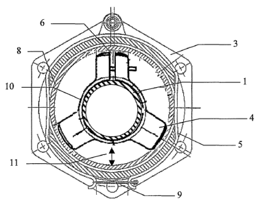
Fig. 1 shows an exemplary embodiment of a spacer according to the present
invention installed between an internal pipe and an external pipe.
Fig. 2 shows a frontal view of an exemplary embodiment of a spacer according
to the
present invention.
Fig. 3 shows a sectional view of an exemplary embodiment of a spacer according
to
the present invention along the section A-A in Fig. 2.
Fig. 4 shows a more detailed view of an exemplary embodiment of a closure for
a
spacer according to the present invention.
Fig. 5 shows a sketch of an exemplary embodiment of a closure according to the
"snap-fit" principle.
Fig. 6 shows an aircraft comprising an exemplary embodiment of the spacer
according to the present invention.
In the following descriptions of Fig. 1 through Fig. 6, identical reference
numbers are
used for identical or corresponding elements.
Fig. 1 shows an exemplary embodiment of a spacer according to the present
invention in its use between an internal pipe and an external pipe of a
pipeline
system. In this case, a pipeline system is understood as any combination of a
rigid or
flexible line, particularly a hose or a cable. Thus, line systems such as pipe
in pipe,
hose in pipe, pipe in hose, or hose in hose may be implemented.
A flange 3 is provided in order to be able to connect multiple line systems to
one
another. A spring 5, which is held together by a rubber band 9, for example,
prevents
the line structure from slipping out of the fastener structure. An internal
pipeline 1 is
enclosed by a pipe clamping structure 10 having distance elements 4 in such a
way
that a pressure is built up on the internal pipe 1 and therefore a slip-proof
connection
is produced. Using the closure according to the present invention, the width
of the
CA 02562280 2006-10-06
WO 2005/106306 PCT/EP2005/004579
-6-
gap 6, which is implemented in one of the at least one distance element 4 or
the pipe
clamping structure 10, is influenced. This width regulation has an effect on
the
diameter of the pipe clamping structure 10 and therefore on the pressure on
the
internal pipe 1.
The distance elements 4 abut the internal wall of the external pipe 8 and thus
hold the
internal pipe at a specified distance to the external pipe. This resulting
intermediate
space 11 is used for ventilation and drainage of leakage liquid and condensed
water
and is required and/or prescribed according to FAA/JAA guidelines for the fuel
system in the fuselage region of aircrafts. The exemplary embodiment of the
present
invention advantageously allows a smaller intermediate space 11 to be
implemented
between internal and external pipes than would be possible using a screw
fastener.
Fig. 2 shows a view of the spacer according to an advantageous exemplary
embodiment of the present invention. A width of the gap 6, which regulates the
pressure on the internal pipe, it is not regulated using a screw fastener, but
rather
using a pin 12, which penetrates into the eye 14 to the depth corresponding to
the
necessary pressure.
The pipe clamping structure 10, the distance elements 4, the pin 12, and the
eye 14
may be manufactured in one piece with the spacer. This avoids multiple
elements
being necessary during mounting to produce the connection. Through the
integration
of the closure, comprising a pin 12 and an eye 14, into the distance element
4, for
example, less space is necessary for installation in the external pipe.
Therefore,
smaller pipe distances 11 may also be achieved than would be possible using
the
known plastic spacers having screws.
An exemplary embodiment of a joint 16 is also shown in Fig. 2. This joint may
be
necessary if the spacer is manufactured from one piece and is to be put onto
the pipe.
However, it is also used for keeping the gap 6 movable.
The number of the distance elements may be arbitrary. The width and depth of
the
distance elements may also be designed arbitrarily. In the arrangement shown
in Fig.
2, they center the internal pipe. However, a non-centering arrangement is also
conceivable.
CA 02562280 2006-10-06
WO 2005/106306 PCT/EP2005/004579
-7-
Fig. 3 shows a sectional view through an exemplary embodiment of the present
invention along the section A-A in Fig. 2. The eye 14, into which the pin 12
is
inserted, a section through the distance element 4, and a part of the pipe
clamping
structure 10 are shown. The width of the spacer is to be selected in
accordance with
the particular requirements.
An advantageous exemplary embodiment of the closure of the present invention
is
shown in Fig. 4. Through the force with which the two halves of the distance
element
4 are pressed together, the pressure of the pipe clamping structure 10 on the
internal
pipe is set in the way described above. The at least one pin and the at least
one eye
are inserted one into the other. At least one hook is attached to the at least
one pin
and in the at least one eye, which are flexible enough in order to allow them
to slide
over one another in one direction. Sliding back is blocked, corresponding to
the
function of a barb. The mutually attached hooks in the eye 14 and on the pin
12 form
a permanent connection, in that they mutually block one another. If the
closure has
the form of a known cable tie, the tensile force and/or gap width may be
predefined
using known auxiliary tools for cable ties and the pressure on the internal
line may
thus be regulated. As a result, the danger of damage through too high a
pressure on
the internal pipe is minimized. If the entire spacer and particularly the
closure are
manufactured from plastic, the danger of damage to the external pipe due to
contact
is minimized. No metal, such as from a screw, then contacts the external pipe.
Fig. 5 shows a fiu ther advantageous exemplary embodiment of the closure for
the
spacer according to the present invention. Two structures which fit one inside
the
other form a snap-fit closure. Both structures have different dimensions. The
first
structure 20 has first dimensions 26 which are enclosed by smaller second
dimensions 24, formed by at least one jaw 22, in such a way that unintentional
sliding out is no longer possible. In order to allow the first dimensions 26
to slide
into the second smaller dimensions, the at least one jaw 22 is designed as
flexible in
order to permit a sufficiently large gap opening temporarily.
Fig. 6 shows an aircraft, particularly a commercial aircraft which may
comprises a
spacer according to the present invention.