Note: Descriptions are shown in the official language in which they were submitted.
CA 02562284 2006-10-06
WO 2005/111550 PCT/US2004/011795
METHOD AND APPARATUS FOR FORCE BALANCING
Background of the Invention
1. Field of the Invention
The present invention relates to force balancing of a Coriolis flow meter.
2. Statement of the Problem
Vibrating flow tube sensors, such as Coriolis mass flow meters, typically
operate by detecting motion of a vibrating flow tube (or tubes) that contains
a
material. Properties associated with the material in the flow tube, such as
mass
flow and density may be determined by processing signals from motion
transducers
associated with the flow tube. The vibration modes of the vibrating material-
filled
system generally are affected by the combined mass, stiffness and damping
characteristics of the containing flow tube and the material contained
therein.
A typical Coriolis mass flow meter may include two flow tubes that are
connected inline with a pipeline or other transport system and convey
material, e.g.,
fluids, slurries and the like, in the system. Each flow tube may be viewed as
having
a set of natural vibration modes including, for example, simple bending,
torsional,
radial and coupled modes. In a typical Coriolis mass flow measurement
application, two U-shaped flow tubes that are oriented parallel to-each other
are
excited to vibrate about their end nodes in the first out-of-phase bending
mode.
End nodes at the ends of each tube define each tube's bending axis. A plane of
symmetry exists half way between the flow tubes. In the most common mode of
vibration, the flow tubes' motion is a periodic bending toward and away from
each
other about the plane of symmetry. Excitation is typically provided by an
actuator,
e.g., an electromechanical device, such as a voice coil-type driver, that
pushes the
flow tubes in a periodic fashion in phase opposition at the tubes' resonant
frequency.
As a material flows through the vibrating flow tubes, the motion of the flow
tubes is measured by motion transducers (commonly called pick-off transducers)
at
points spaced along the flow tube. Mass flow rate may be determined by
measuring time delay or phase differences between motion at the pick-off
transducer locations. The magnitude of the measured time delay is very small;
I
CA 02562284 2006-10-06
WO 2005/111550 PCT/US2004/011795
often measured in nanoseconds. Therefore, it is necessary that the pick-off
transducer output be very accurate.
Coriolis mass flow meter accuracy may be compromised by nonlinearities
and asymmetries in the meter structure or from undesired motion arising from
extraneous forces. For example, a Coriolis mass flow meter having unbalanced
components can cause external vibration of its case and of the attached
pipeline at
the drive frequency of the meter. The coupling between the desired flow tube
vibration and the undesired external vibration of the entire meter means that
damping of the meter's external vibration damps the flow tube vibration, and
that a
stiff meter mount raises flow tube frequency while a soft meter mount lowers
flow
tube frequency. The change in flow tube frequency with mounting stiffness has
been observed experimentally in meters with high external vibration amplitude.
It is
a problem because flow tube frequency is used to determine fluid density.
Frequency is also an indication of flow tube stiffness. Changes in flow tube
stiffness due to mounting stiffness change the calibration factor of the
meter. The
direct coupling between the drive vibration and (via external vibration) the
local
environment also results in an unstable zero signal (a flow signal when no
flow is
present).
The undesired external vibration perturbs the meter output signal in an
amount that depends on the rigidity and damping of the mount. Since the
characteristics of the mount are generally unknown and can change over time
and
temperature, the effects of the unbalanced components cannot be compensated
and may significantly affect meter performance. The effects of these
unbalanced
vibrations and mounting variations are reduced by using flow meter designs
that
are balanced.
The balanced vibration mentioned above traditionally involves only a single
direction of vibration: the Z-direction. The Z-direction is the direction that
the flow
tubes are displaced as they vibrate in phase opposition. This is often called
the
drive direction. Other directions may include the X-direction along the
pipeline and
the Y-direction perpendicular to the Z and X-directions. This reference
coordinate
system is important and will be repeatedly referred to.
There are also secondary sources of unwanted vibration in the Y-direction
resulting from tube geometry. The tube geometry is normally configured so that
the
2
CA 02562284 2006-10-06
WO 2005/111550 PCT/US2004/011795
motion of the tubes' centers of mass is toward. and away from each other about
the
plane of symmetry. Thus the momentum of the oscillation of the tube (and
fluid)
masses largely cancels. In order to avoid Y-motion of the tube centers of
mass,
each center of mass must lie on its respective plane that includes its bending
axis
and is parallel to the symmetry plane. These planes will be referred to as the
balance planes. If the symmetry plane is vertical, the centers of mass must
lie
directly above the bending axes to insure that this Y-direction vibration
cancels.
There is also a secondary vibrating force in the Y-direction resulting from
the
driver, pickoff transducers, and other masses attached to the vibrating
portion of the
flow tubes. The sum of these additional vibrating components will be referred
to,
for simplicity, as the vibrating components. If the center of mass of the
vibrating
components attached to each flow tube is offset from that tube's balance
plane, a
Y-direction vibrating force is generated. This is because the tubes' bending
motion
has a rotation component. If the driver mass is offset from balance plane in
the
Z-direction, then the rotational component of tube motion causes the driver
mass to
have a component of motion in the Y-direction. The source of the Y-direction
motion can be understood by visualizing an extreme offset of a mass. If a mass
is
offset from the balance plane by a 45 degree angle (taken from the bending
axis),
then the rotational component of motion causes it to move equally in the Y and
Z-directions as it vibrates. Equal offset masses on the two vibrating tubes
balance
the forces in the Z-direction but not in the Y-direction.
EP 1 248 084 Al discloses a solution to the problems of Y-vibrations by
affixing an offset mass to the opposite side of a flow tube as the driver mass
so as
to bring the combined center of mass onto the flow tube's balance plane plane.
Secondary unbalanced vibration forces can also be generated in the
Z-direction even when the masses are equal and located on the balance planes
of
the flow tubes. These forces, which are the subject of this invention, are
generated
when the masses affixed to the flow tubes have unequal moments of inertia
about
the lines connecting each respective tube's end nodes (hereafter referred to
as
bending axes).
Summary of the Solution
The present invention improves the balance of the Coriolis flow meter
structure by designing the vibrating components so that the moment of inertia
of
3
CA 02562284 2006-10-06
WO 2005/111550 PCT/US2004/011795
each component is equal to the moment of inertia of the other drive component.
The expression for the moment of inertia of an object is:
I= 5r= an= MR2 (4)
r
Where:
I = the moment of inertia
in = mass
r = the distance from the rotation axis of the component to the increment
of mass o"in.
M = the total mass of the component
R = The radius of gyration of the component
The moment of inertia is greatly affected by the distance term r) being a
squared term. For a driver in a Coriolis flow meter, the rotation axis is
unknown
because the tubes bend rather than rotate. Fortunately, as long as the meter
geometry is symmetric, (equal masses at equal positions) the choice of
rotation
axis does not matter. The parallel axis theorem states that the moment of
inertia
about an axis is equal to the moment of inertia about a parallel axis through
the
center of mass plus the mass times the distance between the two axes squared.
If
we set the moments of inertia of the two drive components about arbitrary
symmetrical axes equal, then the distances from the arbitrary axes to the
center of
masses of the drive components are equal and, with the masses equal, the
parallel
axis term cancels. This means that to set the moments of inertia of the drive
components equal, one only needs to have the centers of mass located
symmetrically and to have the moments of inertia about the centers of mass
equal
to each other.
The components of the driver and the coil including their mounting elements
are fabricated in a distributed manner so that the mass of the magnet and its
mounting elements is equal to the mass of the coil and its mounting elements.
In
addition, the magnet and its elements and the coil and its elements are
configured
and mounted so their centers of mass of these elements when combined with
their
respective tube centers of mass are on the tubes' balance planes. Their
moments
of inertia about their center of masses are also made to be equal. Making the
two
4
CA 02562284 2006-10-06
WO 2005/111550 PCT/US2004/011795
(coil and magnet) elements of equal mass and locating the combined centers of
mass on the balance plane contributes towards a reduction of undesired
vibrations
within the flow meter. Making the two components of equal moments of inertia
contributes to a further reduction in undesired vibration.
Sometimes, however, it is difficult to set the components' moments of inertia
about their centers of mass equal. In these instances an alternate approach
can be
used. Because both mass and moment of inertia impact the meter balance in the
Z-direction, a small moment of inertia for one tube can be balanced by a
larger
mass on that same tube. This technique in essence uses the parallel axis
theorem
to balance moments of inertia about the (assumed position) axis of rotation.
In summary from the above, it can be seen that the driver embodying the
present invention includes a magnet component and a coil component. It can be
further seen that the components embodying the magnet component and the
apparatus embodying the coil component are fabricated and mounted to their
respective flow tubes in such a manner that the mass of the driver component
equals that of the coil component ; that the coil and magnet components have
their
combined (with the flow tube) centers of mass on their respective balance
planes;
and that the magnet component and the coil component have equal moments of
inertia about their centers of mass. The mounting of such a drive coil
component to
the bottom of a first flow tube and the mounting of the magnet component to
the
bottom of a second flow tube provides a dynamically balanced structure which
vibrates the flow tubes in-phase opposition and inhibits the generation of
undesired
internal vibrations.
Further in accordance with the present invention, the pick-off transducers are
designed, fabricated, and mounted on the flow tubes in the same manner as
described for the driver. In other words, each pick-off transducer has a
magnet
component affixed to a first flow tube, a coil component affixed to a second
flow
tube and distributed components that provide dynamically balanced elements
that
do not significantly contribute to the generation of undesired vibrational
forces
within the flow meter.
5
CA 02562284 2006-10-06
ASPECTS
One aspect of the invention includes a Coriolis flow meter comprising:
a first flow tube and a second flow tube adapted to be vibrated in phase
opposition about a plane of symmetry;
a drive system adapted to vibrate each flow tube about axes connecting end
nodes of each flow tube;
first vibrating components including a first vibrating drive system component
affixed to said first flow tube;
second vibrating components including second vibrating drive system
component affixed to said second flow tube;
said first and second vibrating drive system components are of equivalent
size and position such that the moments of inertia of said first flow tube
plus said
first vibrating drive system component are substantially equal to the moments
of
inertia of said second flow tube plus said second vibrating drive system
component;
characterized in that end nodes of said first flow tube and the combined
center of mass of said first flow tube plus said first vibrating drive system
component lie on a first balance plane parallel to said plane of symmetry; and
end nodes of said second flow tube and the combined center of mass of said
second flow tube plus said second vibrating drive system component lie on a
second balance plane parallel to said plane of symmetry.
Preferably, said first and second vibrating drive system components are
sized to have substantially equal masses.
Preferably, said first vibrating drive system component includes a coil
component of a driver affixed to said first flow tube; and
said second vibrating drive system component includes a magnet
component of said driver affixed to said second flow tube and coaxially
aligned with
said coil component.
Preferably, said first vibrating components further include a first pickoff
component, and said second vibrating components include a second pickoff
component.
Preferably, said first pickoff component is affixed to said first flow tube;
and
said second pickoff component is affixed to said second flow tube.
Preferably, said first and second vibrating drive system components are
sized to have substantially equal masses.
6
CA 02562284 2006-10-06
Another aspect of the invention comprises a method of operating a Coriolis
flow meter comprising:
a first flow tube and a second flow tube adapted to be vibrated in phase
opposition about a plane of symmetry;
a drive system adapted to vibrate each flow tube about axes connecting end
nodes of each flow tube; said method comprising the steps of:
affixing first vibrating components including a first vibrating drive system
component to said first flow tube;
affixing second vibrating components including a second vibrating drive
system component to said second flow tube;
sizing and positioning said first and second vibrating drive system
components to be of equivalent size and position such that the moments of
inertia
of said first flow tube plus said first vibrating drive system component are
substantially equal to the moment of inertia of said second flow tube plus
said
second vibrating drive system component;
characterized in that said method comprises the further step of:
positioning end nodes of said first flow tube and the combined center of
mass of said first flow tube plus said first vibrating drive system component
on a
first balance plane parallel to said plane of symmetry; and
positioning end nodes of said second flow tube and the combined center of
mass of said second flow tube plus said second vibrating drive system
component
on a second balance plane parallel to said plane of symmetry.
Preferably, the method further comprises the further steps of sizing said
first
and second vibrating drive system components to have substantially equal
masses.
Preferably, the method further comprises the further steps of:
affixing said first vibrating drive system components including a coil
component of a driver to said first flow tube; and
affixing said second vibrating drive system components including a magnet
component of said driver to said second flow tube and coaxially aligned with
said
coil component.
Preferably, the method further comprises said first vibrating drive system
component furthers include a first pickoff component and that said second
vibrating
drive system component further includes a second pickoff component; said
method
includes the further steps of:
7
CA 02562284 2006-10-06
affixing a first pickoff component to said first flow tube; and
affixing a second pickoff component to said second flow tube.
Preferably, the method further comprises sizing said first and second pickoff
components to have substantially equal masses.
Description of the Drawings
The above and other advantages and aspects of the invention may be better
understood from a reading of the following detailed description taken in
conjunction
with the drawings in which:
FIG. 1 illustrates a conventional prior art Coriolis flow meter;
FIG. 2 illustrates a typical driver for a prior art Coriolis flow meter;
FIG. 3 illustrates a perspective view of a Coriolis flow meter embodying the
present invention;
FIG. 4 illustrates the Coriolis flow meter of FIG. 4 with a portion of the
outer
shell removed;
FIG. 5 illustrates the flow tubes and brace bars of the Coriolis flow meter of
FIG. 3;
8
CA 02562284 2011-10-13
FIG. 6 illustrates the perspective view of the driver D of the Coriolis flow
meter of FIG. 3;
FIG. 7 illustrates a vertical cross sectional view of the flow tubes of FIG. 4
affixed to the driver elements embodying the invention;
FIG. 8 illustrates the details of the driver D affixed to first and second
flow
tubes; and
FIG. 9 illustrates the details of pick-off transducers and the manner in which
they are affixed to the flow tubes.
Detailed Description of the Invention
FIGS. 1-9 and the following description depict specific examples to teach
those skilled in the art how to make and use the best mode of the invention.
For
the purpose of teaching inventive principles, some conventional aspects have
been
simplified or omitted. Those skilled in the art will appreciate variations
from these
examples that fall within the scope of the invention. Those skilled in the art
will
appreciate that the features described below can be combined in various ways
to
form multiple variations of the invention. As a result, the invention is not
limited to
the specific examples described below, but only by the claims and their
equivalents.
DESCRIPTION OF FIGURE 1
FIG. 1 illustrates a Coriolis flow meter 5 comprising a flow meter assembly
10 and meter electronics 120. Meter electronics 120 is connected to meter
assembly 10 via leads 100 to provide density, mass flow rate, volume flow
rate,
totalized mass flow, temperature, and other information over path 126. It
should be
apparent to those skilled in the art that the present invention can be used by
any
type of Coriolis flow meter regardless of the number of drivers, pick-off
sensors,
flow tubes or the operating mode of vibration.
Flow meter assembly 10 includes a pair of flanges 101 and 101'; manifolds
102 and 102'; driver D; pick-off sensors LPO, RPO; and flow tubes 103A and
1036.
Driver D and pick-off sensors LPO, RPO are connected to flow tubes 103A and
103B.
Flanges 101 and 101' are affixed to manifolds 102 and 102'. Manifolds 102
and 102' are affixed to opposite ends of spacer 106. Spacer 106 maintains the
spacing between manifolds 102 and 102' to prevent undesired vibrations in flow
tubes 103A and 103B. When flow meter assembly 10 is inserted into a pipeline
9
CA 02562284 2011-10-13
system (not shown) which carries the material being measured, material enters
flow
meter assembly 10 through flange 101, passes through inlet manifold 102 where
the total amount of material is directed to enter flow tubes 103A and 103B,
flows
through flow tubes 103A and 103B and back into outlet manifold 102' where it
exits
meter assembly 10 through flange 101'.
Flow tubes 103A and 103B are selected and appropriately mounted to inlet
manifold 102 and outlet manifold 102' so as to have substantially the same
mass
distribution, moments of inertia, and elastic moduli about bending axes W--W
and
W'--W' respectively. These axes contain the tube end nodes (stationary points)
for
each flow tube. The flow tubes extend outwardly from the manifolds in an
essentially parallel fashion.
Flow tubes 103A-B are driven by driver D in phase opposition about their
respective bending axes W and Wand at what is termed the first out of bending
mode of the flow meter. Driver D may comprise one of many well known
arrangements, such as a magnet mounted to flow tube 103A and an opposing coil
mounted to flow tube 103B. An alternating current is passed through the
opposing
coil to cause both flow tubes to oscillate in phase opposition. A suitable
drive
signal is applied by meter electronics 120, via lead 110 to driver D. The
description
of FIG. 1 is provided merely as an example of the operation of a Coriolis flow
meter
and is not intended to limit the teaching of the present invention.
Meter electronics 120 transmits sensor signals on leads 111 and 111',
respectively. Meter electronics 120 produces a drive signal on leads 110 which
causes driver D to oscillate flow tubes 103A and 103B in phase opposition.
Meter
electronics 120 processes left and right velocity signals from pick-off
transducers
LPO, RPO to compute mass flow rate. Path 126 provides an input and an output
means that allows meter electronics 120 to interface with an operator.
DESCRIPTION OF FIGURE 2
FIG. 2 illustrates a drive system D for a preferred embodiment of Coriolis
flow meter 5. In a preferred exemplary embodiment, driver D is a coil and
magnet
assembly. One skilled in the art will note that other types of drive systems,
such as
piezoelectric, may be used.
Driver D has a magnet assembly 210 and a coil assembly 220. Brackets
211 extend outward in opposing directions from magnet assembly 210 and coil
CA 02562284 2011-10-13
assembly 220. Brackets 211 are wings which extend outward from the flat base
and have a substantially curved edge 290 on a bottom side that is formed to
receive a flow tube 103A or 103B. The curved edge 290 of brackets 211 are then
welded or in some other manner affixed to flow tubes 103A and 103B to attach
driver D to Coriolis flow meter 5.
Magnet assembly 210 has a magnet keeper 202 as a base. Brackets 211
extend from a first side of magnet keeper 202. Walls 213 and 214 extend
outward
from outer edges of a second side of magnet keeper 202. Walls 213 and 214
control the direction of the magnetic field of magnet 203 perpendicular to the
windings of coil 204.
Magnet 203 is a substantially cylindrical magnet having a first and a second
end. Magnet 203 is fitted into a magnet sleeve (not shown). The magnet sleeve
and magnet 203 are affixed to a second surface of magnet keeper 202 to secure
magnet 203 in magnet assembly 210. Magnet 203 typically has a pole (not shown)
affixed to its second side. The magnet pole (not shown) is a cap that is
fitted to the
second end of magnet 203 to direct the magnetic fields into coil 204.
Coil assembly 220 includes coil 204, and coil bobbin 205. Coil bobbin 205 is
affixed to a bracket 211. Coil bobbin 205 has a spool protruding from a first
surface
around which coil 204 is wound. Coil 204 is mounted on coil bobbin 205
opposing
magnet 203. Coil 204 is connected to lead 110 which applies alternating
currents
to coil 204. The alternating currents cause coil 204 and magnet 203 to attract
and
repel one another which in turn causes flow tubes 103A and 103B to oscillate
in
opposition to one another.
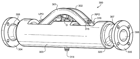
Description of FIG. 3
FIG. 3 discloses a Coriolis flow meter 300 embodying the present invention.
Flow meter 300 comprises a spacer 303 enclosing the lower portion of the flow
tubes 301, 302 which are internally connected on their left ends to flange 304
via its
neck 308 and which are connected on their right ends via neck 320 to flange
305,
and manifold 307. Also shown on FIG. 3 are the outlet 306 of flange 305, left
pick-off LPO, right pick-off RPO and driver D. The right pick-off RPO is shown
in
some detail and includes a magnet structure 315 and a coil structure 316.
Element
314 on the bottom of manifold spacer 303 is an opening for receiving from
meter
electronics 120 the wires 100 that extend internally to driver D and pick-offs
LPO
and
11
CA 02562284 2006-10-06
WO 2005/111550 PCT/US2004/011795
RPO. Flow meter 300 is adapted when in use to be connected via flanges 304 and
305 to a pipeline or the like.
Description of FIG. 4
FIG. 4 is a cut away view of flow meter 300. This view removes the front
portion of manifold spacer 303 so that parts internal to the manifold spacer
may be
shown. The parts that are shown on FIG. 4, but not on FIG. 3, include outer
end
brace bars 401 and 404, inner brace bars 402 and 403, right end flow tube
outlet
openings 405 and 412, flow tubes 301 and 302, curved flow.tube sections 414,
415, 416, and 417. In use, flow tubes 301 and 302 vibrate about their bending
axes W and W'. The outer end brace bars 401 and 404 and the inner brace bars
402 and 403 help determine the location of bending axes W and W'. Element 406
is a mounting fixture for the wires affixed to driver D and pick-offs LPO and
RPO
which are not shown on FIG. 4 to minimize complexity. Surface 411 is the flow
meter inlet; surface 306 is the flow meter outlet.
Element 405 and 412 are the inner surface of the right ends of flow tubes
301 and 302. The bending axes W and Ware shown extending the length of the
flow meter 300.
Description of FIG. 5
FIG. 5 comprises an end view of flow tubes 301 and 302 which are shown as
being outwardly deflected from each other under the influence of driver D
(which is
not shown on FIG. 5). Inner brace bars 402 and 403 as well as outer brace bars
401 and 404 together with outlet openings 405 and 412 are also shown on FIG.
5.
The portrayal of the outward deflection of flow tubes 301, 302 is shown
exaggerated to facilitate an understanding of its operation. In use, the
deflections
of the flow tubes by the driver D are so small in magnitude so as to be
undetectable
by the human eye. Bending axes W and Wfor flow tubes 301 and 302 are also
shown.
Description of FIG. 6
FIG. 6 discloses driver D which has a coil section C and a magnet section M.
Coil section C is shown as having end 601 of a bolt (not shown) which extends
axially through the entirety of the coil section C. Surface 604 is the axial
outer end
of coil section C. Element 602 is a coil spacer that surrounds coil section C.
Surface 603 is a spacer. Element 604 supports the wires (not shown) which are
12
CA 02562284 2011-10-13
connected to the ends of coil winding of coil section C. Element 605 is the
outer
surface of the coil bobbin. Element 606 is the surface around which the wires
of
coil section C are wound. Element 608 are the wires comprising coil section C.
The right hand magnet section includes keeper 609, cylindrical magnet
bracket 610 which surrounds an inner magnet, transition surface 612, counter
weight and magnetic brackets 613, and surface 611 on the left end of magnetic
bracket 613.
In use, coil 608 is energized by a sinusoidal signal from meter electronics
120 over conductors 110. The field created by energized coil 608 interacts
with the
magnetic field at the end of the magnet to cause the coil element C and the
magnet
element M to move axially in-phase opposition under the influence of the
energizing
signal from meter electronics 120. In so doing, the right end portion of coil
element
C on FIG. 6 including the coil 608 and surface 607 move in and out axially of
the
magnetic keeper 609. As shown on FIG. 8, the upper surface of coil spacer 602
is
affixed to a lower surface of flow tube 301. In a similar manner the upper
surface of
magnet bracket 610 is affixed to the lower surface of flow tube 302. The
oscillatory
movement of the coil and magnet components of driver D causes a similar
oscillatory motion of flow tubes 301 and 302 to vibrate in-phase opposition
under
the influence of the drive signal on path 110.
Description of FIG. 7
FIG. 7 is a cross section view of the flow tubes 301 and 302 taken about
their longitudinal axial mid-portion as well as a cross section view of the
elements of
coil component C, magnet component M of driver D. Coil spacer 602 has its top
surface affixed to the lower surface of flow tube 301. The top surface of
magnet
bracket 610 is affixed to the lower surface of flow tube 302. Coil spacer 602
and
magnet bracket 610 may be affixed to the flow tubes by means of brazing and/or
spot welding. Bolt 701 having end 601 is contained within coil spacer 602 and
extends inwardly through spacer 603 and terminates in element 606. Element 606
is affixed to element 704 which includes the surface about which the coil 608
of
FIG. 6 is wound.
The magnet M component of driver D includes element 702 on its outer right
end. The left end of magnet M is element 703; the middle portion of magnet M
is
element 710. The right hand portion 702 is contained within counter weight
613.
When component coil C of driver D is energized, the right hand portion of coil
13
CA 02562284 2006-10-06
WO 2005/111550 PCT/US2004/011795
component C and the left hand portion 703 of magnet component M vibrate
axially
inwardly and outwardly with respect to each other and in so doing cause a
similar
inward and outward vibration of flow tubes 301 and 302.
When driver D vibrates flow tubes 301 and 302, flow tube 301 vibrates about
bending axis Wand while flow tube 302 vibrates about bending axis W. This is
more clearly shown on FIGS. 4 and 5. Vertical line 716 is in the balance plane
for
flow tube 301. Balance plane 716 contains the bending axis Wand is parallel to
the plane of symmetry 708. Vertical line 717 is in the balance plane for flow
tube
302. Balance plane 717 contains bending axis W and is also parallel to the
plane
of symmetry 708 which is mid way between planes 716 and 717.
Flow tubes 301 and 302 vibrate like a tuning fork about their respective
bending axes W' and W. However, the two flow tubes by themselves are not a
perfectly dynamically balanced structure and therefore may be assumed to
generate a low level of undesired vibrations within the Coriolis flow meter of
which
they area part.
FIG. 7 shows the bending axes W' and W located slightly inward from the
centerlines 706 and 707 of flow tubes 301 and 302. These bending axes W' and W
are often located on the flow tube centerlines 706 and 707. However in the
present
invention as shown on FIG. 7, bending axes W' and W are shown offset the flow
tube center lines 706 and 707 because of the mass and stiffness of the
structures
to which they are attached. The flow tube centers of mass 712 and 715,
(neglecting the attached components), are on the tube centerlines 706 and 707.
As
the tubes bend inwards, their centers of mass 715 and 712 follow
circumferential
paths about the bending axes W' and W. It can thus be seen that as the centers
of
mass approach their respective balance planes 716 and 717, they also move
slightly upward. Likewise, as the centers of mass 715 and 712 of the flow
tubes
move away from their respective balance planes 716 and 717, they move
downward. Unless balanced, this vertical movement of the tube centers of mass
715 and 712 would cause the meter to shake in the Y-direction.
The driver of a typical flow meter also has a mass that is dynamically
unbalanced when affixed to the flow tubes of the typical Coriolis flow meter.
Such a
driver is shown in FIG. 2 and can seen as comprising a first structure 220
that is
affixed to a first flow tube and a second structure 210 that is affixed to a
second
14
CA 02562284 2006-10-06
WO 2005/111550 PCT/US2004/011795
flow tube. Such a driver adds significant mass to the vibrating structure of
the flow
tubes. Also the driver adds the mass in such a manner that the bulk of the
mass is
positioned in the space between the two flow tubes. This mass comprises
elements 204, 203, 205, 213, and 214 of the driver of FIG. 2.
If the structure of the driver of FIG. 2 were added to the flow tubes 301,
302,
instead of the driver D of the present invention, the flow meter would likely
remain
unbalanced since the centers of mass of the driver components of FIG. 2 would
be
positioned between the radial centers 706 and 707 of flow tubes 301 and 302.
These centers of mass would lie far to the inner side of the balance plane 716
and
717. Because of this location, the drive component centers of mass would go
down
as the tubes move toward each other and up as they move away from each other.
This would cancel the y-direction unbalance from the bare flow tubes but,
unfortunately, with prior art drivers, the effect of the drive component
offsets
overwhelms the effect of the flow tube center of mass offset from the balance
plane. This dynamic unbalanced would in turn generates significant amount of
undesired vibrations in such a flow meter.
The driver D of the present invention includes coil component C and a
magnet component M which are affixed to the bottom of respective ones of flow
tubes 301 and 302 in such a manner as to enable the flow tubes to operate with
a
minimum of undesired vibrations. This is achieved in accordance with the
present
invention by designing, fabricating, and configuring the coil component C and
magnet component M so that they each comprises a dynamically balanced
structure having equal and identical inertial characteristics. Elements are
affixed
individually to the bottom of flow tube 301 and 302. They are positioned in
axial
alignment with each other so that the axial center of the coil and the magnet
have a
common center axis that enables the two elements to vibrate in-phase
opposition
along their common axis. The affixing of the drive element C with its center
of
mass 718 to flow tube 301 with its center of mass 715 creates a combined
center of
mass 727 that lies on the balance plane 716. Likewise, the affixing of the
drive
element M with its center of mass 713 to flow tube 302 with its center of mass
712
creates a combined center of mass 714 that lies on the balance plane 717.
Locating the combined centers of mass on balance planes 716 and 717 ensures
CA 02562284 2011-10-13
that the added components do not disturb the vibrational balance of the meter
and
thus do not generate any undesired vibration in the Y-direction.
The coil C component and the magnet M component of driver D are
designed, fabricated, and configured to have the vibrational characteristics
next
described. First, the mass of the coil C component is made equal to the mass
of
the magnet M component of driver D. The center of mass 718 of the coil and the
center of mass 713 of the magnet are made equal distance from the bending axes
W' and W. Next, the moment of inertia is configured for the coil C component
and
the magnet M component so that the moment of inertia of each of these is made
essentially equal. The moment of inertia of each of these elements may be
expressed as
I= 1r2.an
Where:
I = the moment of inertia of the component
m = mass of each incremental element
r = the distance from each incremental element to the center of
mass of the component
Lastly, the center of mass of each drive component is located such that the
combined centers of mass of each drive component and its respective flow tube
are
located on the balance planes 716 and 717. Designing a driver to these rules
ensures a dynamically balanced structure that enables the flow tubes to be
vibrated
in-phase opposition while avoiding the generation of undesired vibrations.
Description of FIG. 8
FIG. 8 discloses the details of the driver D of FIG. 6 and 7 when affixed to
the bottom of flow tubes 301 and 302. FIG. 8 shows the end 601 of the bolt
that
extends through coil C. It further shows end surface 614 of the coil section
and the
coil spacer cover 602, coil surface 603, wire terminal 604. FIG. 8 also shows
the
elements 609, 610, 612, and 613 of the magnet component M. FIG. 8 shows
conductors 806 and 807 extending from bracket 802 to coil terminals 604.
Conductors 806 and 807 are connected by conductors 110 (not shown) to apply
energizing signal 110 from meter electronics 120 to coil section C. Brackets
801,
16
CA 02562284 2011-10-13
802, 803, 804, and 805 are mounting brackets to support conductors 806 and
807.
The magnet bracket 610 is affixed to the bottom of flow tube 302 in the same
manner that the coil spacer element 602 is affixed to the bottom of flow tube
301.
Description of FIG. 9
FIG. 9 illustrates further details of pick-offs RPO and LPO of FIG. 3 affixed
to
the top of flow tubes 301 and 302. Each pick-off has a coil component C and a
magnet component M in the same manner as does the driver D. The coil C
component has a spacer 315 affixed to the top of flow tube 301; the magnet M
component has a spacer 316 affixed to the top of flow tube 302. Pick-off RPO
has
conductors 907 which are connected to conductor paths 111 and 111' of FIG. 1
by
means not shown in detail on FIG. 9. These conductors are supported by bracket
906. The coil C component has a element 902 and 904 to support the coil
conductors as well as further having an axially inner end surface 903. Magnet
M
component has an inner end portion 905 that corresponds to element 609 of
magnet component M of FIG. 6.
The pick-offs RPO and LPO are designed, configured, and fabricated in the
same manner as described for the driver so that each component has equal
masses, centers of mass on the balance planes, and equal moments of inertia.
This ensures that the parts of the pick-offs comprise dynamically balanced
structures that can be affixed to the flow tubes as shown so as to enable the
flow
tubes to be operated in a manner that does not generate undesired vibrations.
17