Note: Descriptions are shown in the official language in which they were submitted.
CA 02562286 2006-10-10
WO 2005/103533 PCT/US2005/007801
TITLE OF THE INVENTION
Coil Gasket
BACKGROUND OF THE INVENTION
A wide variety of gaskets are known for use in sealing applications.
Porous expanded polytetrafluoroethylene (PTFE) is widely used today as a
gasket material. As disclosed in U.S. Patent No. 3,953,566 to Gore, this
material has numerous properties making it highly desirable as a gasket. These
properties include being readily compressible and conformable, being
chemically resistant, having relatively high strength, and being far less
prone to
creep relaxation and loss of sealing pressure than non-expanded, non-porous
PTFE alone.
Furthermore, gaskets made from biaxially or multiaxially expanded
PTFE have improved sealing performance as compared to uniaxially expanded
PTFE gaskets. For example, gaskets made from multiaxially expanded PTFE are
resistant to creep relaxation and cold flow in multiple directions. The multi-
directional tensile strength in multiaxially expanded PTFE gaskets provides
circumferential and radial strength to the gasket and increases the cut
through
resistance of the gasket. Enhanced radial strength and cut through resistance
provided by multiaxially expanded PTFE is achieved when the plane of
expansion of the expanded PTFE is substantially parallel to the flange surface
on
which the gasket is installed.
In many sealing applications, the gasket is used to seal the junction
between flanges, such as between pipes. Expanded PTFE is a desirable material
for the gaskets because the expanded PTFE gasket can be placed between the
flanges, and the flanges can then be pressed together with the application of
force, such as by tightening of bolts. This application of force compresses
the
expanded PTFE. As the expanded PTFE is compressed, its initial pore volume
is reduced, thus densifying the expanded PTFE. Particularly with metal-to-
metal flanges, it is possible to apply sufficient force (or "stress") to the
flanges
to fully densify the expanded PTFE. Thus, in at least part of the expanded
PTFE
CA 02562286 2006-10-10
WO 2005/103533 PCT/US2005/007801
gasket, the pore volume may be reduced to substantially zero, preventing fluid
contained within the pipes from leaking between the flanges by the densified,
non-porous PTFE gasket, which seals the flanges.
In many applications, particularly when harsh chemicals are used which
would readily break down the metal or the metal could contaminate the chemical
which is being transported or housed, it is common to use glass-lined steel,
glass, or fiberglass reinforced plastic ("FRP") piping and vessels. Because
this
equipment is often used with extremely harsh chemicals, there is a great
desire
to use PTFE gaskets to seal the connecting flanges of this equipment because
of
the well-known extraordinary chemical resistance of PTFE. Unfortunately, non-
expanded, non-porous PTFE gaskets are generally not conformable enough to
effectively seal this type of equipment.' In the case of glass-lined steel
flanges,
although there is a relatively smooth finish, there is often a large amount of
unevenness or lack of flatness associated with the flanges. This unevenness or
lack of flatness requires the gasket to conform to large variations around the
perimeter as well as between the internal and external diameter of the flange
in
order for an effective seal to be created. Thus, a non-expanded, non-porous
PTFE gasket is not conformable enough to provide an adequate seal in many of
these applications.
Because expanded PTFE is conformable, it would be desirable to use
expanded PTFE to seal these commonly uneven flanges. Unfortunately, in
many applications it is not possible to apply sufficient force to the flanges
to
create enough gasket stress to fully densify the expanded PTFE gasket to
create
an effective seal. For example, glass-lined steel piping flanges, glass
flanges, or
FRP piping flanges may deform, fracture, or break upon the application of a
high amount of stress. Thus, in these applications, an expanded PTFE gasket
may not be completely densified to reach a non-porous state, and therefore
does
not become leak proof, because the maximum stress that can be applied to the
flanges without breaking them is not sufficient to densify the gasket. In some
constructions where expanded PTFE gasket is not densified to a substantially
non-porous state, leakage can occur through the residual porosity within the
gasket. Often, this leakage is detected immediately after the installation of
the
gasket through either a "sniffing" technique or a "bubble test". In the bubble
CA 02562286 2006-10-10
WO 2005/103533 PCT/US2005/007801
test, a solution such as soapy water is applied to the gasketed flange and an
internal air pressure is applied to the piping system or vessel. If a leak of
a
sufficient rate is present, bubbles will form in the soapy water solution. In
some
cases, a leak may exist but at a rate small enough not to form a bubble. In
such
cases and where corrosive chemicals are being processed, the leak may persist
for months or years where the corrosive chemicals can eventually leak through
the gasket undetected and attack the flange bolts or clamps resulting in a
catastrophic failure of the flange.
As discussed in U.S. Patent Publication 2003/0003290 in the name of
Hisano et al., methods are known in industry for producing gaskets by wrapping
ePTFE films on a mandrel to produce a tubular element whereby the tubular
element is sliced into rings to produce gaskets. Within the laminated layers
of
these gaskets, a compact ePTFE film is interposed to prevent fluid penetration
leakage through the gasket. These methods for producing such gaskets are
limited in the size of gaskets that can be produced. The laminate thickness in
these methods is typically limited to a maximum of about 10 mm to 15 mm
which corresponds to the a gasket width of only 15 mm or less. Laminate
thicknesses greater than this are difficult to restrain during the sintering
process
and can result in significant density gradients within the laminate. Gasket
widths
in typical applications, especially with larger diameter gaskets, are
generally on
the order of 25 mm and greater. Furthermore, when the tubular element is
sliced,
the laminate layers of the ePTFE are oriented perpendicular to the gasket
upper
and lower surfaces. Therefore, the transverse direction of expansion of the
ePTFE is oriented in the z direction or thickness direction of the gasket and
provides little or no strength to the gasket in the radial direction.
U. S. Patent No. 6,485,809, in the name of Minor et al., teaches a low
stress to seal gasket construction comprising a multilayer, unitary gasket
including at least one inner layer of expanded PTFE disposed between a first
substantially air impermeable outer layer and a second substantially air
impermeable outer layer, and a substantially air impermeable region bridging
the first and second substantially air impermeable layers. By "low stress to
seal" is meant a gasket which provides a substantially air tight, or air
impermeable, seal upon the application of a relatively low stress (i.e., a
stress
CA 02562286 2006-10-10
WO 2005/103533 PCT/US2005/007801
below that required to fully densify a porous expanded PTFE gasket, generally
less than about 20,700 kPa (3000 psi)). This patent teaches gaskets which are
stamped or cut from multilayered laminated sheets formed by wrapping layers
around a mandrel, and subjecting gaskets to compressive treatment to compress
a discreet portion and form an air impermeable region. While this patented
construction may overcome many challenges in creating a low stress to seal
gasket, there are limitations to the sizes of gaskets that can be produced
when
cutting gaskets from sheet goods. The largest size gasket that can be produced
when cutting from sheet gasketing cannot be larger than the sheet size itself.
Another concern with the manufacturing of such large size gaskets from sheet
gasketing materials is the cost associated with producing such gaskets. For
example, the manufacturing efficiencies of cutting gaskets from sheet stock
can
be relatively low especially with large diameter gaskets..
U. S. Patent No. 4,990,296 to Pitolaj teaches a method of welding
together filled sintered PTFE components, wherein large diameter gaskets can
be formed in sections by welding the ends of the sections together. This
method,
while perhaps suitable for sintered filled PTFE, would not be suitable for
soft,
porous expanded PTFE which would densify as a result of the applied heat and
pressure at the welded joint. Densification would result in thinner, hard and
non-conformable sections within the gasket. A gasket having variable thickness
and softness would not be able to effectively seal fragile flanges such as
glass
lined steel and FRP flanges.
U. S. Patent No. 5,964,465 to Mills et al. teaches a biaxially expanded
PTFE form-in-place type gasket. Form-in-place gaskets have the advantage of
being able to be formed to any size flange without the limitations of gaskets
cut
from sheet stock such as low material utilization rates. Form-in-place gaskets
made in accordance with the teachings of Mills et al., comprised of biaxially
expanded PTFE, may have additional advantages offered by the biaxially
expanded PTFE such as chemical resistance, dimensional stability, and
resistance to creep relaxation. However, as previously noted, since adequate
gasket stress cannot be applied to densify the ePTFE, these gaskets cannot
effectively seal glass lined steel and FRP flanges.
4
CA 02562286 2006-10-10
WO 2005/103533 PCT/US2005/007801
In PCT publication WO01/27501 A1 to Dove et al., a form-in-place
gasket comprising an inner layer of expanded PTFE and substantially air
impermeable outer layers that are bridged by a substantially impermeable
region
is taught. The substantially air impermeable outer layers and substantially
air
impermeable region are intended to prevent permeation through the expanded
PTFE gasket material. The purpose of this gasket construction is to provide a
tight seal at the low stresses where ePTFE alone can not be fully densified by
preventing leakage through the porous ePTFE. However, gaskets constructed
according to the teachings of WO 01/27501 are subject to a number of
disadvantages. For example, outer air impermeable layers made of
incompressible materials such as full density PTFE or densified expanded PTFE
may increase the stiffness of the gasket, making it too rigid for a form-in-
place
gasket. It is desirable for form-in-place gaskets to be flexible so that they
can be
formed to the geometry of the flange.
Further, form-in-place gaskets comprising biaxially expanded PTFE are
typically joined at the ends by skive-cutting the ends and overlapping the
skive
cut ends as taught in U.S. Patent No. 5,964,465. Form-in-place gaskets
constructed in accordance with PCT publication WO01/27501 A1 to Dove et al.
having the outer impermeable layers, cannot be joined by overlapping the ends
of the tape using the skive cutting technique without compromising the air
impermeable nature of the material. When a skive cut is made through the outer
air impermeable layers, porous expanded PTFE may be exposed, providing a
leak path through the gasket.
In U.S. Patent Publication No. 2003/0003290 A1 to Hisano et al., a
sealing material in the form of a tape is taught which consists of laminated
layers of porous expanded PTFE which are slit into strips having a height
greater than the width, and wherein the laminated end faces on the long side
of
the laminated strip are in contact with the tightening surface. A plurality of
the
laminated strips may be joined together on the laminated surfaces of the
laminate with tetrafluoroethylene-hexafluoropropylene copolymer or
tetrafluoroethylene-perfluoroalkyl vinyl ether copolymer film. It is further
taught that at least one layer may be interposed within the laminate for
preventing fluid penetration. In the form of a closed ring or gasket where the
CA 02562286 2006-10-10
WO 2005/103533 PCT/US2005/007801
longitudinal beginning and end of the tape has been joined, the layers of
expanded PTFE and the layer for preventing fluid penetration are vertically
oriented when the gasket is installed on a flange surface. The layers intended
to
prevent fluid penetration in the radial direction may provide the gasket with
low
stress to seal capability by preventing leakage through the porous ePTFE. For
gaskets made according to this method, the longitudinal strength of the
expanded PTFE provides strength to the gasket in the circumferential direction
when the gasket is installed on a flange surface. However, with the ePTFE
layers laminated in the width direction, the transverse directional strength
of the
ePTFE is oriented in the vertical or "z" direction of the gasket. Therefore,
little
to no strength is provided to the gasket in the radial direction. Therefore,
gaskets
taught in U.S. Patent Publication No. 2003/0003290 A1 would be prone to cold
flow in the width direction and lack dimensional stability. For gasketing
applications involving glass lined steel flanges it is preferred that the
gasket
material to be dimensionally stable to prevent fracture of the glass lining.
Form-in-place gaskets, especially biaxially expanded PTFE gaskets,
have the disadvantage of requiring an overlap of the ends of the tape to form
the
closed shape of a gasket. It is usually necessary for skilled operators to
perform
the installation of these gaskets in order to insure the skive cut is done
correctly.
Improper installation may result in leakage at the overlap site. In many
applications form-in-place gaskets are not deemed acceptable because of the
overlapped ends which is perceived as a weak point within the gasket. Because
of this concern there is reluctance to using biaxially expanded PTFE form-in-
place gaskets.
It would be desirable to provide a gasket that can be formed from a tape
to avoid the low yields and high costs associated with cutting gaskets from
sheet
stocks and that would also not be limited in size or shape. It would also be
desirable for such a gasket to be a continuous and unitary gasket without
joints
resulting from overlapping tape ends. It would be further desirable for such a
gasket to be a conformable, creep resistant, and chemically resistant gasket
that
can seal at the low stresses common to applications in which glass lined steel
and F1~P flanges are used, and that does not fracture upon the application of
high
compressive stresses commonly used to seal steel flanges. It is therefore one
CA 02562286 2006-10-10
WO 2005/103533 PCT/US2005/007801
object of the present invention to provide a continuous, unitary gasket made
from an expanded PTFE tape that provides a substantially air tight seal upon
the
application of low stress and to provide a method for manufacturing such a
gasket.
SUMMARY OF THE INVENTION
The present invention provides a unitary structure, such as a gasket,
formed from winding at least one length of ePTFE tape and joining the tape
windings. Interposed between the windings of the tape is a substantially air
impermeable layer. Where a gasket is formed, the substantially air impermeable
layer prevents penetration or leakage through the gasket in the radial
direction.
Gaskets of the present invention had significantly lower leak rates than
traditional sheet or tape gaskets when tested for sealability. A decrease in
leak
rate of about 1.5 orders of magnitude or more was realized with the inventive
gaskets having a substantially air impermeable layer as compared with gaskets
cut from ePTFE sheet and formed from ePTFE tape without any impermeable
layers interposed therein. The lower leak rate demonstrated by the gaskets of
the
present invention is attributable in part to the substantially parallel
orientation of
the plane of expansion of the expanded PTFE with the flange surface and the
incorporation of substantially air impermeable layers interposed within the
gasket.
In another aspect, the invention provides a method for producing a
gasket comprising the steps of providing an ePTFE tape and a material capable
of forming a substantially air impermeable layer, winding the ePTFE tape and
the substantially air impermeable layer, to form alternating windings of ePTFE
and the substantially air impermeable layer, and joining the windings.
BRIEF DESCRIPTION OF THE DRAWINGS
A fuller understanding of the present invention will be gained by
reference to the following detailed description when read in conjunction with
accompanying drawings. It should be understood that the invention is not
limited to the precise arrangement shown.
Fig. 1 is a top view and cross-section views of a gasket in accordance with
the
present invention.
x ig. ~ is a top view of a gasket in accordance with the present invention.
CA 02562286 2006-10-10
WO 2005/103533 PCT/US2005/007801
Fig. 3 is a top view of a gasket in accordance with the present invention.
Fig. 4 is a three-quarter perspective view of a form-in-place gasket.
Fig. 5 is a three-quarter perspective view of a tape material and orientation.
Fig. 6 is an exploded view of a fixture and a method of assembling a tape
having
a barrier layer.
Fig. 7 is a side view of a fixture and method of assembling a gasket in
accordance with the present invention.
Fig. 8 is a graphical representation of leak rate results of gaskets at a
gasket
stress of about 6 MPa
Fig. 9 is a side cross-sectional view of a test apparatus used to measure
sealability of gaskets.
Fig. 10 is a three-quarter perspective view of a gasket tape and orientation.
Fig. 11 is a graphical representation of Wide-Angle X-ray Scattering Test
results.
DETAILED DESCRIPTION OF THE INVENTION
The preferred embodiment of the present invention is directed to a gasket
that provides a substantially air impermeable seal with low load upon the
tightening surfaces, and with low stress applied to the gaskets. In one
preferred
embodiment, a gasket is formed comprising alternate windings of a tape
comprising ePTFE and a substantially air impermeable layer, each winding at an
increasing distance around the inner diameter or inner periphery of a gasket.
Gaskets of the present invention exhibit excellent dimensional stability and
resistance to creep relaxation. The present invention is further directed to
novel
methods for forming the novel structures of the present invention. Methods are
disclosed for joining or bonding together windings of ePTFE tape, such as
multilayered porous expanded PTFE tapes, with a substantially air impermeable
layer between the tape windings. The novel methods provide low stress to seal
gaskets, and are particularly useful for large size gaskets.
As previously stated, by "low stress to seal gasket" is meant a gasket,
such as a gasket of the present invention, which provides a substantially air
tight, or air impermeable, seal upon the application of a relatively low
stress
(i.e., a stress below that required to fully densify a porous expanded
CA 02562286 2006-10-10
WO 2005/103533 PCT/US2005/007801
polytetrafluoroethylene (ePTFE) gasket, generally less than about 20,700 kPa
(3000 psi)).
By "air impermeable" as used herein is meant resistant to the transport of
air through a material. Permeability may be measured using any known
technique, such as ASTM D-1434-82 (2003).
Exemplary embodiments of the present invention are illustrated in Figs.
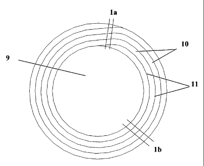
1-3. Figs. 1-3 illustrate preferred unitary gaskets each comprising an inner
periphery or diameter 9 and at least two windings or rotations of at least one
porous expanded PTFE tape 10. The windings of the ePTFE tape are alternated
with windings of at least one substantially air impermeable layer 11 also
wound
in an increasing distance around the inner periphery or diameter. Preferably,
each winding or rotation of the at least one expanded PTFE tape 10 is
alternated
and joined by the at least one substantially air impermeable layer 11.
Illustrated in Figs. la and 1b are cross-sections of a representative gasket
of the present invention. The expanded PTFE tape has upper and lower tape
surfaces 16 corresponding to upper and lower gasket surfaces, and side
surfaces
18 extending between the upper and lower tapes surfaces. Preferably, as shown
in Figs. la and 1b, the substantially air impermeable layer 11 is bonded to
side
surfaces 18 of mufti-layered porous ePTFE tape, the side surfaces extending
between upper and lower laminate tape layers.
Gaskets of the present invention may be formed from one tape or a
plurality of tapes, and is not particularly limited by the number of tapes
that may
be joined to form the gasket. For example, more than one tape may be wound
simultaneously around a form to form tape windings. The at least one tape
making up the gasket may be monolithic or multilayered porous expanded
PTFE. Preferred porous ePTFE tapes suitable for use in the present invention
are multilayered laminate tape wherein the plane of expansion of the ePTFE is
in the x-y plane of the tape, and the ePTFE layers including upper and lower
tape layers of the tape are parallel to the plane of expansion. Fig. 5
illustrates a
multilayer tape suitable for use in the present invention having upper and
lower
tape layers (56) in the X-Y plan of the tape. Where the ePTFE tape is
monolithic, it is preferred that the plane of expansion of the ePTFE is
parallel to
the x-y plane of the tape. Preferably, the x-y plane of the tape is
substantially
CA 02562286 2006-10-10
WO 2005/103533 PCT/US2005/007801
parallel to the sealing surface. The plane of expansion of ePTFE can be
determined, for example, by Wide-Angle X-ray Scattering test methods, as
described herein.
Preferred porous expanded PTFE comprises microporous expanded
PTFE as taught in U.S. Pat. Nos. 3,953,566 and 4,187,390, incorporated herein
by reference. PTFE may be expanded uniaxially, biaxially, or multiaxially, and
preferably has a density of less than 1.8 g/cc, more preferred less than 1.2
g/cc,
further preferred less than 1.0 g/cc, and a most preferred density of less
than 0.8
g/cc. While not limited by a number of porous expanded PTFE layers, preferred
multilayered tape is formed from multiple self adhered porous expanded PTFE
layers, made by any method known in the art for forming multilayered porous
expanded PTFE tapes; methods suitable for use in the present invention are
described, for example, in U.S. Pat. No. 5,964,465, and 6,485,809 which are
hereby incorporated herein by reference. Suitable tape is commercially
available, for example, under the trade names GORE-TEX~ Gasket Tape,
GORE-TEX~ Series 300 Gasket Tape and GORE-TEX~ Series 600 Gasket
Tape (W.L. Gore & Assoc., Inc., Elkton, MD).
While preferably all layers of multilayer ePTFE tape are ePTFE,
alternately, one or more tape layers may comprise materials other than a PTFE
material to provide desired properties to the gasket. For example, one or more
of polymeric films, metal foils, metal screens or the like may be provided to
the
multilayered tape to enhance properties to the resulting gasket. In a
preferred
embodiment a gasket is formed from at least one multilayered laminated ePTFE
tape in which upper and lower laminate layers are ePTFE.
At least a portion of the porous expanded PTFE, or at least one layer of
multilayered PTFE tape, may be coated or filled to provide desired properties
to
the gasket. For example, expanded PTFE may be coated to provide properties
such as resilience, electrochemical responsiveness, added strength, further
reduced creep relaxation, and the like. Additionally, porous expanded PTFE
may be filled with various fillers, for example, such as those used to fill
expanded microporous PTFE sheets as taught in U.S. Pat. Nos. 4,096,227 and
4,985,296, incorporated herein by reference. Suitable particulate fillers may
include, for example, inorganic materials such as metals, semi-metals, metal
to
CA 02562286 2006-10-10
WO 2005/103533 PCT/US2005/007801
oxides, glass, ceramic and the like. Alternatively, other suitable particulate
fillers may include, for example, organic materials selected from activated
carbon, carbon black, polymeric resin, graphite and the like. In one preferred
embodiment at least one layer of multilayered porous expanded PTFE tape
comprises at least one filler. Preferably, the at least one filler comprises
at least
one of silica, barium sulfate and glass beads.
At least one substantially air impermeable layer is alternately wound
with at least one porous ePTFE tape for at least two windings of the ePTFE
tape
at an increasing distance around a center point such as a gasket inner
periphery.
The substantially air impermeable layer may be bonded to the ePTFE tape prior
to tape winding or during the winding process. Substantially air impermeable
layers prevent fluid from permeating through the gaskets in the radial
direction
providing the low stress to seal nature of the gasket. Substantially air
impermeable materials of the present invention are more air impermeable than
the porous expanded PTFE materials used to form the tape. Materials suitable
for use in the present invention comprise an air impermeable material, or at
least
one material capable of forming an air impermeable layer having a permeability
to air that is less than the porous expanded PTFE of the tape material.
Preferred
air impermeable materials comprise fluoropolymers, including, but not limited
to, tetrafluoroethylene/ hexafluoropropylene copolymer (FEP),
tetrafluoroethylene/ (perfluoroalkyl) vinyl ether copolymer (PFA), PTFE,
densified expanded PTFE, and combinations thereof. Preferred are melt
processable fluoropolymers. Most preferred are PFA and FEP. Air
impermeable material may comprise porous PTFE impregnated with fillers such
as an elastomer, a fluoroelastomer, a perfluoroelastomer, or a
perfluorosilicone
elastomer. Preferred are air impermeable layers having a width of about 0.01
mm to 0.5 mm when calculated, for example, by measuring the distance
between two ePTFE tape windings that are aligned along side surfaces and
joined by the substantially air impermeable layer.
Gaskets of the present invention are preferably formed from at least one
porous ePTFE tape wound around the outer periphery of a form or die at an
increasing distance from the form or die until at least two turns around the
form
are achieved. It is preferred that the ePTFE is wound continuously for at
least
11
CA 02562286 2006-10-10
WO 2005/103533 PCT/US2005/007801
two windings or rotations around the form or die at increasing distances from
the outer periphery to form a coil. At least two sequential or adjacent ePTFE
windings are preferably joined by interposing alternating windings of at least
one substantially air impermeable material between the ePTFE windings. The at
least two windings of at least one ePTFE tape and at least one substantially
air
impermeable material are joined to form a unitary gasket. The shape of the die
and gasket is not limited and therefore may be formed into any desired shape,
such as circular or non-circular, including but not limited to a substantially
circular, elliptical, rectangular or square shape. Thus, the term "coil" as
used
herein refers to any shape formed from multiple rotations or windings of at
least
one ePTFE tape at an increasing distance around a center point, an inner
gasket
periphery, or an outer periphery of a die or form. Each rotation of the ePTFE
tape winding is aligned along the length of adjacent ePTFE tape windings at an
increasing distance from the die or the inner diameter/periphery of the
gasket.
Preferably, the tape windings are aligned along tape side surfaces, and at
least
one air impermeable layer extends between the tape side surfaces to join each
winding of ePTFE of the tape to form a unitary gasket. A preferred gasket,
such
as a circular gasket, comprises an inner diameter and at least two spirals
comprising alternating rotations of at least one porous multilayer ePTFE tape
and at least one substantially air impermeable layer. The spirals of ePTFE
tape
and the substantially air impermeable layer preferably rotate in an increasing
distance around the inner diameter for at least two rotations of the ePTFE.
The
preferred ePTFE tape is a multilayer tape having upper and lower tape layers,
and side surfaces extend between upper and lower tape layers. The rotations of
ePTFE tape are aligned along tape side surfaces and joined at the side
surfaces
by the alternating spiral of at least one substantially air impermeable layer
between the rotations of ePTFE.
Where the tape comprises a plurality of laminated layers, the tape side
surface is defined by the laminated edge (e.g., Fig. 5, at 58) which extends
between upper and lower tape layers (Fig. 5, 56). Multiple tape windings are
aligned along tape side surfaces and the at least one substantially air
impermeable layer is positioned on the laminated edge between the adjacent
ePTFE tape side surfaces. The substantially air impermeable layer extends from
12
CA 02562286 2006-10-10
WO 2005/103533 PCT/US2005/007801
the upper tape layers to the lower tape layers of the tape. Preferably, the
air
impermeable layer extends substantially completely between the upper and
lower tape layers, e.g. generally in the x-z plane of the tape, for the entire
length
of the wound tape. Preferred gaskets comprise multilayered porous multiaxially
expanded PTFE tape having upper and lower laminate tape layers in the x-y
plane of the tape, that define upper and lower gasket surfaces. Where gasket
comprises monolithic porous ePTFE tape, upper and lower tape surfaces in the
x-y plane of the tape correspond to, or define the upper and lower gasket
surfaces. It is preferred that alternating windings of at least one ePTFE tape
and
at least one substantially air impermeable layer are wound so that the plane
of
expansion of the ePTFE tape is in the x-y plane of the tape. It is preferred
that
the plane of expansion is oriented substantially parallel to upper and lower
gasket surfaces of an uncompressed gasket providing strength in at least both
the
circumferential and radial directions.
As illustrated in Fig. la and 1b, where tape side surfaces are
perpendicular to the upper and lower gasket surfaces, the air impermeable
layer
joined thereto extends substantially along the x-z plane of the tape
preventing
the flow of liquid in the radial direction through the gasket. The length of
the
tape forming the windings of the inventive gasket prevents leakage through the
longitudinal direction of the tape. Preferred gaskets of the present invention
have
a substantially uniform thickness across the width of an uncompressed gasket.
Therefore, uncompressed gaskets of the present invention preferably have a
uniform thickness across the upper and lower gasket surfaces between inner and
outer gasket diameters.
The novel gaskets of the present invention are preferably formed from
the following novel methods.
A process is provided comprising the steps of providing a length of at
least one porous ePTFE tape having upper and lower tape layers or surfaces,
and
side surfaces extending between upper and lower tape layers or surfaces, and
providing at least one material capable of forming a substantially air
impermeable layer. The method further comprises coiling the at least one
ePTFE tape and the at least one material capable of forming a substantially
air
impermeable material, forming alternating windings of the ePTFE tape and the
13
CA 02562286 2006-10-10
WO 2005/103533 PCT/US2005/007801
at least one material capable of forming a substantially air impermeable layer
at
increasing distances around a center point, and joining the alternating
windings
to form a unitary structure of the at least one ePTFE tape and the at least
one
substantially air impermeable layer.
In one preferred embodiment, the at least one ePTFE tape and at least
one substantially air impermeable layer are coiled or wound around a form
defining the inner periphery of a gasket, such as a die, forming alternating
windings. Tape is aligned along the tape side surfaces with the at least one
substantially air impermeable layer interposed between the ePTFE tape
windings. The at least one ePTFE tape is preferably aligned wherein upper and
lower tape layers or surfaces, and the plane of expansion of the ePTFE, are
both
in the x-y plane of the gasket. The method further comprises joining the
windings of the at least one ePTFE tape and the at least one substantially air
impermeable layer along tape side surfaces. A unitary gasket is formed
comprising at least two windings of at least one ePTFE tape around an inner
periphery, each ePTFE winding alternated with at least one substantially air
impermeable material. In a preferred embodiment, at least one substantially
air
impermeable layer is first formed or bonded on the two side surfaces of at
least
one porous ePTFE tape prior to winding at least one ePTFE tape to form a
gasket. A method for forming or bonding the substantially air impermeable
layer
on the ePTFE tape side surfaces comprises the steps of providing a length of
tape having upper and lower surfaces or layers and tape side surfaces
extending
the length of the tape between upper and lower surfaces or layers; providing a
material capable of forming a substantially air impermeable layer; aligning
the
material along the length of the ePTFE tape on the tape side surface; and
forming the substantially air impermeable layer on the two ePTFE tape side
surfaces.
Preferably, the substantially air impermeable material is a melt
processable fluoropolymer and the step of forming or bonding the at least one
substantially air impermeable layer to the ePTFE tape comprises the steps of
contacting at least one ePTFE side surface and the at least one substantially
air
impermeable material; applying pressure and heating the side surface of the
porous efT~'E tape and the at least one substantially air impermeable material
14
CA 02562286 2006-10-10
WO 2005/103533 PCT/US2005/007801
above the melt temperature of the porous ePTFE and the at least one material
to
weld the heated material and the porous ePTFE together. Sufficient pressure is
applied to bond the ePTFE tape side surface and the material, forming a
substantially air impermeable layer on the side surface of the tape. Each of
the
steps of forming a substantially air impermeable layer on at least one ePTFE
tape side surface, including the steps of 1 ) contacting the ePTFE tape side
surface and the at least one material capable of forming a substantially air
impermeable layer, and 2) applying heat and 3) pressure to the materials, may
be
performed simultaneously or sequentially. Further, a substantially air
impermeable layer may be formed on at least one ePTFE tape side surface as a
step-wise process for a portion of a tape length, or as a continuous process
along
the entire desired length of the tape.
A release layer may be provided between the material capable of
forming the air impermeable layer and the pressure and/or heat source to
prevent
sticking. The substantially air impermeable material is bonded to a desired
length of the porous ePTFE tape, which is preferably the entire tape length
used
to form a gasket. Fig. 6 illustrates a portion of a hot press assembly and a
method for welding a substantially air impermeable layer on to the side
surface
of an ePTFE tape.
Alternately, the material capable of forming a substantially air
impermeable layer may, for example, be coated onto the side surface of an
ePTFE tape along the length of at least one tape. Coating may be accomplished
by any means, such as spraying, brushing, or powder coating.
Preferred methods of forming a gasket comprising alternate windings of
at least one porous ePTFE tape and at least one substantially air impermeable
layer preferably comprises the steps of providing a length of porous ePTFE
tape
having a substantially air impermeable material layer along the length of the
tape; winding the ePTFE tape around a form or a die; applying heat at a
juncture
of two sequential ePTFE tape windings, contacting and applying pressure and
joining sequential windings until the desired width of the gasket is formed.
Fig.7 illustrates a portion of a fixture for winding and welding the at least
one
ePTFE tape and at least one substantially air impermeable layer to form a
gasket. Preferably, where the substantially air impermeable layer is applied
to
CA 02562286 2006-10-10
WO 2005/103533 PCT/US2005/007801
both side surfaces of at least one porous ePTFE tape, the heating step
comprises
applying heat at a juncture of two substantially air impermeable layers of
sequential ePTFE windings, above the melt temperature of the substantially air
impermeable layer. The method further comprises applying pressure to weld the
two substantially air impermeable layers together to join the sequential ePTFE
windings.
The preferred steps of forming the gasket including the steps of 1 )
winding at least one ePTFE tape around a die, 2) applying heat at a juncture
of
the windings of the at least one ePTFE tape side surfaces having the
substantially air impermeable layer bonded thereto, and 2) contacting and 3)
applying pressure to the heated ePTFE side surfaces to weld the ePTFE
windings, may be performed simultaneously, or sequentially. Further, the steps
of forming the gasket may be performed step-wise or as a continuous process
until the desired geometry of the gasket is formed.
In another embodiment, the steps of forming a substantially air
impermeable layer on ePTFE side surfaces and the steps of winding the ePTFE
tape and joining the ePTFE windings are combined in one continuous process.
Gaskets and methods of forming the materials of the present invention
are exemplified, but not limited, by the examples presented below.
EXAMPLES
Example 1
An ePTFE/PFA coil gasket of the present invention was produced in the
following manner.
A length of approximately 6 meters (20 feet) of Gore-Tex~ Series 600
Gasket Tape (ePTFE tape) having a nominal width of approximately 10 mm
(0.39 inches) and a nominal thickness of approximately 6 mm (0.23 inches) was
obtained from W.L. Gore & Associates, Inc. of Newark, DE. A Teflon~ PFA
Film, Type LP having a width of approximately 13 mm (0.5 inches) and a
thickness of approximately 0.025 mm (0.001 inches) was obtained from E.I. du
Pont de Nemours, Inc. of Wilmington, Delaware.
The PFA film was welded to the two side surfaces of the ePTFE tape
along the entire length of the ePTFE tape. The PFA film was welded to the
first
side surface of the ePTFE tape using a hot press substantially similar to the
press
illustrated in Fig. 6 with upper press platen 61 heated to abaut 375°~
and the
16
CA 02562286 2006-10-10
WO 2005/103533 PCT/US2005/007801
lower press platen 62 kept at ambient temperature. The upper and lower press
platens 61 and 62 had a length of approximately 200 mm (8 inches). Therefore,
200 mm sections of the ePTFE tape were coated at a time. The ePTFE tape 63
was placed in a channel 64 in the lower platen with the side surface 66 of the
ePTFE tape extending approximately 0.25 mm to 0.5 mm above the top surface
of the lower platen 62. The PFA film 65 was placed on the side surface of the
ePTFE tape and centered. Kapton~ polyimide film 68 was obtained from E.I. du
Pont de Nemours, Inc. of Wilmington, Delaware. A piece of the Kapton~ film
68 was placed on top of the PFA film 65 as a release layer to prevent the PFA
from sticking to the heated upper platen 61. The upper platen 61 was lowered
with sufficient pressure being applied so that the upper platen 61 was in
contact
with the lower platen 62. The upper platen 61 was held in place for
approximately five seconds and then lifted from the lower platen 62 . The
Kapton~ film 68 was removed from the formed ePTFE/PFA composite tape.
The ePTFE/PFA composite tape was removed from the channel in the lower
platen and the next 200 mm section of the ePTFE tape was inserted and the
lamination process was repeated. After the entire length of the ePTFE tape was
coated on the one side surface with the PFA film, the excess PFA film was
trimmed from the ePTFE/PFA composite tape using a razor blade. The opposite
side surface of the ePTFE tape was coated with the PFA film following the same
procedures as above. The excess PFA film was trimmed from the ePTFE/PFA
composite tape using a razor blade.
An assembly for making a gasket is illustrated in Figs. 7a and 7b. A
circular die 71 was provided to a drive shaft 72, the die 71 having a diameter
of
about 203 mm (8 inches[) and a slot 73 for receiving an end of a tape. One end
74 of the ePTFE/PFA composite tape 75 was secured in the die 71 by placing
the end of the tape in the slot and tightening set screws 77. One of the PFA
coated side surfaces 76 of the composite tape was in contact with the edge of
the
die corresponding to the circumference. The die was rotated through one
revolution creating the first winding 78 around the circumference of the die.
A
lower tape guide 79 was positioned to apply pressure in the direction
indicated
by the arrows of Fig. 7b to the tape via the air cylinder 80. The air cylinder
pressure was set to 8 psig (55 kPa). A Leister Hot Jet S hot air gun 81
(Leister
Process Technologies, Sarnen, Switzerland was positioned so that the tip of
the
nozzle was located approximately 6 mm from the juncture 82 of the ePTFE tape
windings. The hot air gun was set to a temperature setting of 6 (maximum)
corresponding to a rated temperature of about 600°~ and air flow
setting of 4
~maximL..°n) corresponding to a rated air flow of about 80 liters/min.
The die
17
CA 02562286 2006-10-10
WO 2005/103533 PCT/US2005/007801
rotational speed was set to approximately 0.25 rpm [using the speed control
potentiometer on the drive system (Rapid-Air, Rockford, IL).] The PFA of each
side surface was melted by the hot air 82 and the side surfaces of adjacent
ePTFE tape windings 75 and 78 each having melted PFA were contacted to
bond the tape side surfaces. The coiling process continued until approximately
six windings 78 had been wound around the die. The lower tape guide 79 was
lowered and the die and coiled composite gasket were removed from the drive
shaft.
The coiled gasket having alternating winding of porous ePTFE and air
impermeable PFA was formed and trimmed to final inner and outer diameter
dimensions of about 220 mm (8.66 inches) and about 273 mm (10.75 inches),
respectively, using a LMI Laser Cutter. The gasket had a final thickness of
about 6.6 mm (0.26 inches) and a mass of approximately 131 g. The composite
gasket made according to this example was tested for sealability in accordance
with the procedures of the Sealability Test described herein. The results can
be
seen in Fig. 8.
Example 2
An ePTFE/PFA composite coil gasket of the present invention was
produced substantially according to the procedures described in Example 1.
The gasket was trimmed to final inner and outer diameter dimensions of
about 220 mm (8.66 inches) and about 273 mm (10.75 inches). The gasket had a
final thickness of about 6.9 mm (0.27 inches) and a mass of approximately 138
g. The composite gasket made according to this example was tested for
sealability in accordance with the procedures of the Sealability Test
described
herein. The results can be seen in Fig. 8.
Example 3
An ePTFE/PFA composite coil gasket of the present invention was
produced substantially according to the procedures described in Example 1.
The gasket was trimmed to final inner and outer diameter dimensions of
about 220 mm (8.66 inches) and about 273 mm (10.75 inches). The gasket had a
final thickness of about 6.6 mm (0.26 inches) and a mass of approximately 106
g. The composite gasket made according to this example was tested for
sealability in accordance with the procedures of the Sealability Test
described
herein. The results can be seen in Fig. 8.
18
CA 02562286 2006-10-10
WO 2005/103533 PCT/US2005/007801
Comparative Example 4
A GORE-TEX GR~ sheet gasketing gasket having an inner diameter of
approximately 220 mm (8.66 inches), an outer diameter of approximately 273
mm (10.75 inches), a thickness of 5.8 mm (0.23 inches), and a mass of 76 g was
obtained from W.L. Gore & Associates, Inc. of Newark, Delaware.
The gasket according to this example was tested for sealability in
accordance with the procedures of the Sealability Test described herein. The
results can be seen in Fig. 8.
Example 5
An ePTFE/FEP composite coil gasket of the present invention was
produced substantially according to the procedures described in Example 1 with
the following exceptions. The initial width of the ePTFE tape was
approximately
20 mm (0.79 inches). A 13 mm wide FEP film was obtained from E.I. du Pont
de Nemours, Inc. of Wilmington, Delaware and bonded to the two side surfaces
of the ePTFE in accordance with the procedures described in Example 1 for
forming the composite tape. The excess FEP was trimmed from the tape using a
razor blade. The diameter of the die used was about 430 mm (17 inches). The
die rotational speed was set to about 0.1 revolutions per minute.
Approximately
five windings of the composite tape were coiled around the die and bonded
using the hot air gun settings as in Example 1. A gasket having alternating
rotations of ePTFE and air impermeable FEP was formed, and trimmed to final
inner and outer diameters of about 435 mm and 537 mm, respectively, using a
general purpose gasket cutter.
The gasket had a final thickness of about 6 mm (0.25 inches). The gasket
was tested for leakage in accordance with the procedures of the Leakage Test
described herein. The results can be found in Table 1.
Table 1: Leakage Test Results
Leaks a
Measurements
m /m/s
Sam 1e ID 1 2 3
Exam 1e 5 0.0121 - 0.0086
Comparative Example 2.41 - 1.25
6
19
CA 02562286 2006-10-10
WO 2005/103533 PCT/US2005/007801
Comparative Example 6
A sample of GORE-TEX~ Series 600 Gasket Tape as represented by
Fig. 5 was obtained from W.L. Gore & Associates, Inc. of Newark, DE having a
nominal thickness of 6 mm and a nominal width of 55 mm and length of
approximately 1800 mm. A double-sided pressure sensitive adhesive having a
width of about 25 mm was applied to one surface of the tape along the length
of
the tape and centered between the two edges. The pressure sensitive adhesive
was a styrene butadiene rubber (SBR) based adhesive with a polyester carrier
film and with a release paper on one side.
The tape was formed into a gasket as illustrated in Figs. 4a and 4b, with
the longitudinal ends 42 joined by a skive cut 43. The gasket was tested for
leakage in accordance with the procedures of the Leakage Test described
herein.
The results can be found in Table 1.
TEST METHODS AND PROCEDURES
Sealability Test Procedures
The sealability of gaskets made substantially according to Examples 1-3
and Comparative Example 4 was determined by measuring leak rates using a
computer controlled, hydraulically driven test fixture, as seen in Fig. 9.
Gaskets
9lwere installed in the test fixture on the lower platen 92. The gasket
samples
were compressed by hydraulic press 98 between the upper 93 and lower 92
platens to a stress of about 6 MPa. The internal pressure in the high pressure
zone 94 was increased to about 27 bar using nitrogen gas as supplied by the
compressed air bottle 97 as the test fluid. The internal pressure was
maintained
in the high pressure zone throughout the test period. As the nitrogen gas
leaked
past the gasket sample, the pressure in the low pressure zone 95 increased.
The
change in pressure in the low pressure zone was monitored by the pressure
differential switch 96. The leak rate was calculated by the test fixture's
software
program based on the change in pressure in the low-pressure zone after a 90
minute (5400 second) dwell time and based on the following equation:
LR = (/~n;trogen X Vo X OP)/(d X II X Ot X palm)
where:
LR = leak rate (mg/m x sec)
pn~crogen= density of nitrogen at ambient conditions (mg/cm3)
~Ia = volume within test flange (cm3)
CA 02562286 2006-10-10
WO 2005/103533 PCT/US2005/007801
d = average gasket diameter (m, meters)
d = (outer diameter + inner diameter)/2
OP = change in internal pressure in the low pressure zone = Po - Pf
Po = initial internal pressure at t = 0 seconds (bar)
Pf= final pressure at t = 0t (bar)
~t = test time (seconds)
paten = atmospheric pressure (bar)
The leak rates for each example tested can be seen in Fig. 8. The graph
shows that all of the inventive examples tested, Examples 1 through 3, had
significantly lower leak rates than the comparative example. A decrease in
leak
rate of at least about 1.5 orders of magnitude was realized with the inventive
examples having substantially air impermeable layers as compared with
Comparative Example 4 which is an ePTFE gasket without any impermeable
layers interposed therein. The lower leak rate demonstrated by the inventive
examples is attributable in part to the incorporation of the substantially air
impermeable layers) oriented substantially perpendicular to the sealing
surfaces
in the gasket, and further, to the substantially parallel orientation of the
plane of
expansion of the expanded PTFE with the flange surface.
Leakage Test Procedures: Glass Lined Steel Test Fixture
The leakage behavior of gaskets made substantially according to
Examples 5 and Comparative Example 6 were tested on an actual glass lined
steel flange through a thermal cycle. The inner and outer diameters of the
glass
lined steel flanges were approximately 430 mm and 520 mm, respectively. Test
gaskets were installed on the lower flange. The ePTFE tape in Comparative
Example 6 was installed using the skive cut overlapping technique taught in
U.S. Patent No. 5,964,465 to Mills et al. The first end of the tape samples
were
skive cut on a diagonal with a skive length of about 50 mm. The release paper
was removed from the adhesive on the tape samples. The adhesive layer held the
tapes in position as the tape was being formed around the lower flange. The
trailing end of the tape was positioned on top of the skive cut on the leading
end
of the tape. The second skive cut was made on the trailing end of the tape so
that
a smooth transition was created at the overlap of the leading and trailing
ends of
the tape. The upper flange was positioned on top of the gasket and aligned
with
the lower flange. The flanges were bolted together using twelve M24 clamps.
The clamps were tightened to a torque of 111 N-m generating a line force load
~n the gasket of approximately 200N/mm. The line force is equal to the total
21
CA 02562286 2006-10-10
WO 2005/103533 PCT/US2005/007801
force on the gasket supplied by the tightening of the clamps divided by the
average circumference of the gasket. The average circumference is determined
by multiplying the average diameter of the gasket [(gasket outside diameter +
gasket inside diameter)/2] by pi. Ten minutes after the initial torque, the
clamps
were retightened to 111 N-m. The internal pressure was then increased to 6 bar
using compressed air. After a 24 hour dwell under pressure at ambient
temperature, the first leakage measurement was recorded. The fixture was then
loaded in to an oven and re-pressurized to 6 bar with compressed air. The
temperature of the oven was set to 200°C for a period of 16 hours.
After cooling
to room temperature, the second leakage measurement was recorded. The
clamps were then retightened to 111 N-m to reestablish the 200 N/mm line force
on the gasket. The fixture was re-pressurized to 6 bar with compressed air.
The
third and final leakage measurement was then taken. The leak rates were
determined based on the change in internal pressure in the test fixture as
measured by a differential pressure switch according to the following
equation:
LR = (pair x V° x OP)/(d x II x ~t x paten)
where:
LR = leak rate (mg/m x sec)
density of air at ambient conditions (mg/cm3)
Vo = volume within test flange (cm3)
d = average gasket diameter (m, meters)
d = (outer diameter + inner diameter)/2
DP = change in internal pressure = P° - Pf
P° = initial internal pressure at t = 0 seconds (bar)
Pf= final pressure at t = 0t (bar)
0t = test time (seconds)
pacm = atmospheric pressure (bar)
The leak rates measured for each example can be seen in Table 1. The
results in Table 1 show that after the 24 hour dwell at room temperature the
inventive example (Example 5) had significantly lower leak rate as compared
with Comparative Example 6. After the 16 hour dwell at 200°C, all of
the
gaskets experienced gross leakage (pressure change too large to be measured by
the differential pressure switch). After the re-tightening of the clamps back
to
the 111 N-m torque, the inventive example again had significantly less leakage
than the comparative example.
22
CA 02562286 2006-10-10
WO 2005/103533 PCT/US2005/007801
Wide-Angle X-ray Scattering Measurements
The plane of expansion of a multiaxially expanded PTFE gasket tape
material was verified with wide-angle X-ray scattering measurements.
Samples of gasket tape material were cut from a length of GORE-TEX~
Series 300 Gasket Tape with a nominal thickness of 3 mm. The GORE-TEX~
Series 300 Gasket Tape material is comprised of multiple layers of a biaxially
expanded PTFE membrane laminated together in the thickness direction. The
ePTFE membrane layers are expanded in the longitudinal (x-direction) and
transverse (y-direction) directions with the thickness oriented with the z-
direction. Therefore, the plane of expansion is the x-y plane of the membrane
and the Gasket Tape.
As illustrated in Fig. 10 test samples were cut parallel to the x-y plane
180, y-z plane 181 and the x-z plane 182 from the GORE-TEX Series 300
Gasket Tape. Four rectangular samples were cut using an LMI Laser Cutter
from each planar orientation to approximately 3 mm by 15 mm by 0.5 mm. For
the samples cut from the
x-y plane 180, membrane layers were removed from a section of the nominally 3
mm thick tape to produce a tape section with a nominal thickness of 0.5 mm.
From this 0.5 mm thick section, the rectangular test samples were cut to a
width
and length of about 3 mm and 15 mm, respectively, with the sample width
parallel to the Gasket Tape width (y-direction) and the sample length parallel
to
the Gasket Tape length (x-direction). In these samples, the plane defined by
the
sample length and width (x-y plane) is parallel to the membrane layers and the
plane of expansion of the ePTFE.
For the test samples cut in the x-z plane 182, two parallel cuts,
approximately 0.5 mm apart, were made in the x-direction of the 3 mm thick
Gasket Tape material. From this 0.5 mm wide and 3 mm thick section the 15
mm long test samples were cut. For these samples, the 3 mm by 15 mm area
defined the x-z plane.
For the test samples cut in the y-z plane 181, two parallel cuts,
approximately 0.5 mm apart, were made in the y-direction of the 3 mm thick
Gas'.cet Tape material. From this 0.5 mm wide and 3 m..m thick section the 15
23
CA 02562286 2006-10-10
WO 2005/103533 PCT/US2005/007801
mm long test samples were cut. For these samples, the 3 mm by 15 mm area
defined the y-z plane.
All measurements were made in transmission mode using a Rigaku R-
Axis IV Image Plate X-ray Analyzer mounted on a Rigaku Ultra 18 kW rotating
anode x-ray generator with a graphite monochromator and a 0.3mm pinhole
collimator. Operating conditions on the generator for all experiments were
SOkV and 200mA. Radiation type was Cu Ka,. Sample-to-detector distance was
set at approximately 120 mm, and calibrated using a silicon powder standard.
All measurements were made on a temperature-controlled stage maintained at
approximately 2411 °C. Two-dimensional image data was processed using
Rigaku R-Axis image processing software to obtain I vs. 20 scans. The scans
were collected by radial integration over the angular range from 200°
to
2055° in increments of X20=0.044°.
The I vs. 20 scans were processed using Jade 6.1 XRD Pattern
Processing & Identification software purchased from Materials Data, Inc. The
data processing procedure was as follows. Scans and associated air scattering
background files were read into the software and scaled to match maximum
intensity counts in the range of 28=6°-8°. The air scattering
file was then used to
define the scattering background and subtracted from the I vs. 20 scans
obtained
from the samples. Finally, the position and intensity of the primary
scattering
peaks were identified using the software's standard peak search routine. It
should be noted that the data was originally collected in two-dimensional
form,
and was analyzed without any correction into a form that would be directly
analogous to data collected with a linear detector.
A typical I vs. 20 diffraction scan is shown in Fig. 11. All scans show
the characteristic diffraction peaks of polytetrafluoroethylene. The strongest
peak, occurring near 28=18.1°, is attributable to the { 100}
crystalline planes.
The next most intense diffraction peaks occur near 28=37.1° and
20=41.4°, and
are attributed to the {107} and {108} crystalline planes, respectively (see
Eduard S. Clark, "Unit Cell Information on Some Important Polymers, "
Chapter 30, Physical Properties of Polymers Handbook, James E. Mark, Ed.
IVew York,: American Institute of Physics, 1996).
24
CA 02562286 2006-10-10
WO 2005/103533 PCT/US2005/007801
The GORE-TEX~ Series 300 Gasket Tape material is comprised of
multiple layers of a biaxially expanded PTFE membrane laminated together in
the thickness direction. Orientation, or texture, is developed in the PTFE
within
the membrane during expansion that is retained within the Gasket Tape. Due to
this texture, the relative intensity of the { 100} and { 108} peaks in
diffraction
scans obtained from the samples of the Gasket Tape is a function of the
physical
orientation of the sample relative to the thickness direction of the Gasket
Tape.
When Gasket Tape samples are measured with the x-ray beam incident
on the sample face in a direction that is perpendicular to the plane of
expansion
(x-y plane), the intensity of the { 108} peak relative to the intensity of {
100}
peak is higher than for samples measured in other orientations. For example,
in
the case where the samples were cut parallel to x-y plane and measured with
the
x-ray beam perpendicular to the x-y plane (parallel to the z direction), the I
vs.
20 diffraction scans show higher relative { 108} peak intensities than scans
from
samples cut in the x-z and y-z planes and measured with the x-ray beam
perpendicular to those faces (parallel to the y direction, and parallel to the
x
direction, respectively). This is illustrated in Table 2, in which data are
presented from the analysis of I vs. 20 diffraction scans for twelve (12)
samples,
four (4) cut from three (3) different orientations relative to the thickness
direction of the Gasket Tape. In Table 3, the relative { 108 } peak intensity
is
reported as a percentage of the { 100} peak intensity, to normalize for sample-
to-
sample variation in thickness, density, or measurement time. As illustrated in
Fig, 10 and noted in Table 2, samples with x-z orientation were measured such
that the x-ray beam was incident on the x-z face in a direction parallel to
the y-
direction. Similarly, samples with y-z orientation were measured such that the
x-ray beam was incident on the y-z face in a direction parallel to the x-
direction,
and samples with x-y orientation were measured such that the x-ray beam was
incident on the x-y face in a direction parallel to the z direction. Samples
were
cut and positioned such that the x-ray beam was incident on the 3 mm by 15 mm
face.
2s
CA 02562286 2006-10-10
WO 2005/103533 PCT/US2005/007801
Table 2.
Sample Plane Beam Direction {108} Peak Intensity
of 100 Peak
1 x-y parallel to 35.7
z
4 x-y parallel to 32.5
z
7 x-y parallel to 32.9
z
12 x-y parallel to 33.3
z
2 y-z parallel to 6.2
x
6 y-z parallel to 6.5
x
9 y-z parallel to 6.1
x
y-z parallel to 5.7
x
3 x-z parallel to 13.5
y
5 x-z parallel to 12.2
y
8 x-z parallel to 12.1
y
11 x-z parallel to 13.2
y
In Table 2, the { 108} relative peak intensity, expressed as a percentage
of the corresponding { 100} peak intensity within a single I vs. 20 x-ray
scan, is
given for the variety of gasket sections. Samples 1, 4, 7, and 12 which were
measured in the x-y orientation with the x-ray beam parallel to the z
direction
have significantly higher relative { 108} diffraction intensities than the
samples
measured in the x-z orientation or in the y-z orientation with the x-ray beam
directed as stated above. Thus, the highest { 108} relative peak intensity is
measured for samples positioned such that the x-ray beam is incident on the
sample in a direction 1 perpendicular to the plane of expansion of the
biaxially
expanded PTFE membrane layers. Therefore, comparison of { 108 } relative
peak intensities in different orientations can be used to identify the plane
of
expansion of ePTFE in a Gasket Tape.
26