Note: Descriptions are shown in the official language in which they were submitted.
CA 02562294 2006-10-05
WO 2005/105682 PCT/BE2005/000056
Roller and rotational drivinct device.
Description
[0001] The invention relates to a roller from a refractory material, for
example in vitreous silica,
for transporting a flat article provided at its end with a new arrangement for
rotationally driving it
as well as to an assembly of such a roller and its driving device.
[0002] In the glass or metallurgical industry, the conveyance of glass or
metal in the course of
being elaborated and under the form of plates, sheets, foils or continuous
strips, is carried over
on rollers arranged parallel together. This transportation is generally
performed at high
temperature.
[0003] These rollers are rotationally driven at a liner speed equal to this of
the glass or metal so
as not to damage the surface.
[0004] More particularly, in the case of the transportation of a metal strip
or band, every roller is
supported on a steel shaft passing through an axial bore of the roller and
projects beyond the
roller at its both ends, ensuring simultaneously its rectilinear support and
its centering during the
rotation. To this end, this axial bore presents a smooth cylindrical
longitudinal inner surface
which is precisely coaxial to the external longitudinal face of the roller and
shows a
predetermined diameter.
[0005] Generally, the rotational driving of the roller is ensured by a driving
device comprising
fingers parallel to the shaft, arranged around each of the ends thereof and
borne by a support
rotating with the shaft. Every pin engages into a recess formed in the lateral
face of the roller,
i.e. in the thickness of the roller which is comprised between the
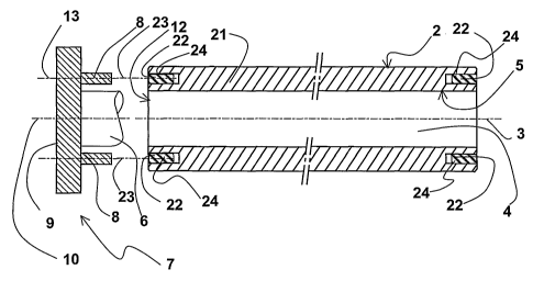
longitudinal bore and the
external longitudinal face. There is however also a driving device using pins
perpendicular to the
shaft. Such a device is disclosed in the document WO-A1-99/15305. It can be
easily
understood that such a system cannot perform efficiently when the roller and
the driving device
are formed from materials having different thermal expansion coefficient.
[0006] As a variant of the conventional device, a roller whose lateral faces
are provided with
one or more recesses opening on the external surface of the roller is known
from the document
J P-A-10-324534.
[0007] A defect which can appear with such a driving device acting on such
rollers is that the
edge of the roller, weakened by the presence of the indentations, is broken in
its part comprised
between the indentation and the axial bore. In particular, during use of the
roller, the increase in
temperature to which the roller and the driving device are subjected causes
significant
dimensional differences which increase the risk of break of the roller around
its driving
indentations.
[0008] While such a defect is not directly detrimental to the proper
performance of the roller, the
presence of silica fragments close to the metal or the glass being conveyed,
to the driving device
or even inside the longitudinal bore can become worrying.
[0009] This defect occurs in particular on small diameter rollers, for example
of 120 mm, inside
CA 02562294 2006-10-05
WO 2005/105682 PCT/BE2005/000056
2
which there remains rather little matter between the bore and the
indentations.
[0010] The present invention aims at remedying this defect by proposing a new
arrangement
for rotationally driving a roller.
[0011] It relates therefore to a roller made from a refractory material and
comprising an external
surface, an inner surface and two side surfaces, at least one of the side
surface having
indentations parallel to the roller axis for receiving rotationally driving
pins. More particularly, the
present invention relates to roller wherein the indentations are spaced apart
from the external or
inner surface.
[0012] WO-A2-2004/097319 already proposes a solution to the above problem. The
present
invention is an alternative solution.
[0013] The present invention has for first object a roller from a refractory
material for
transporting a flat article, according to claim 1. According to the invention,
at least one of the
indentation is provided with a metal jacket. Thereby, the stress and the
shocks caused by the
driving device and particularly by the pins hitting the walls of the
indentation are homogeneously
distributed. In this case, the jacket is preferably constituted of a metal
pipe adjusted into the
indentation. Advantageously, this pipe is slit longitudinally so as to provide
some elasticity.
[0014] According to the invention, it is meant by pin any means able to engage
into an
indentation of the roller to transmit a rotation couple. This term comprises
the above described
fingers.
[0015] The present invention also relates to an assembly comprising:
- such a roller and
- a driving device comprising pins borne by a rotary support and able to
engage in the roller
indentations,
said assembly being characterized in that at least one pin and the indentation
which receives the
pin are formed so that a significant play, according to a radial direction of
the roller, stands
between the pin and the metal jacket in the indentation when said pin has
engaged into the said
indentation.
[0016] The invention remedies the above indicated problem by leaving a
significant play
between the pin and the metal jacket in the radial direction of the roller,
i.e. in a direction passing
through the roller axis.
[0017] It is meant by significant play a free space permitting the movement of
the pin, on a
stroke larger than the play only due to the manufacturing tolerances, as well
as to a functional
play necessary for engaging the pin into the metal jacket. The significant
play is advantageously
selected so as to permit a pin movement in the indentation during the
temperature changes
occurring during the use of the roller. To this end, the play is of at least 3
mm. Preferably, this
play is larger than 4 mm.
[0018] This particular configuration of the indentations and pins provides a
better distribution of
the whole bearing surface between the driving device and the roller which
contributes to the
reduction of the stress concentration risk on the edges of the roller.
CA 02562294 2006-10-05
WO 2005/105682 PCT/BE2005/000056
3
[0019] Advantageously, the longitudinal inner surface is a bearing surface of
the roller with
which the roller bears on a bearing shaft. The external face of the roller
remains intact and
continuous which can prove preferable in particular applications wherein the
whole width of the
roller is used for transporting the article in the course of being elaborated.
[0020] In order to facilitate the understanding of the invention, embodiments
will now be
described, only as examples which do not limit the scope of the invention,
with the help of the
enclosed figures wherein:
- figure 1 is a longitudinal section of a vitreous silica roller used for
transporting glass,
according to the prior art;
- figure 2 is a left view of the prior art roller of figure 1;
- figure 3 is a view similar to figure 2 of a roller according to the
invention;
- figure 4 is a left view of the roller of figure 3;
- figure 5 is a perspective view of a metal jacket according to the invention;
[0021] On the drawings, the elements are depicted at ambient temperature, i.e.
in the position
they occupy when the roller is not in use for transporting glass. The thermal
expansions of the
hot elements cause relative displacements between the elements which are not
depicted here.
[0022] In the prior art, which is illustrated by figures 1 and 2, a roller 1
of cylindrical shape is
made from vitreous silica by a known process.
[0023] This roller has a length of several meters and a diameter which,
according to the type of
roller, can be comprised between 10 and 20 centimeters.
[0024] An external longitudinal surface 2 of the roller serves as bearing
surface for glass (not
shown) in the process of being elaborated which is transported with several
rollers of the same
kind arranged parallel together.
[0025] The glass rolls on the external longitudinal surface 2 of the roller
which, to this end, must
have a very smooth surface and a very cylindrical shape of axis 3.
[0026] An axial bore 4 is formed inside the roller, coaxial with the external
longitudinal surface
2. The precisely cylindrical shape of the wall 5 of the bore 4 is obtained by
a precise machining
which ensures that this inner longitudinal surface has a cylindrical shape of
the same axis 3.
[0027] The bore 4 permits the passage of a bearing shaft 6 (partly shown)
which maintains the
roller rectilinear and supports it by the bearing surface 5, while allowing
its rotation.
[0028] The rotational driving of the roller 1 is ensured, as is well known, by
a driving device 7
present on both ends of the roller but of which only one half, shown on the
left of the roller on the
figure is described here.
[0029] The driving device comprises six driving fingers 8, parallel to the
axis 3 and borne by a
support 9 rotarily mounted around an axis 10 which merges with the axis 3 when
the roller is
mounted on the driving device.
[0030] In the example shown, the bearing shaft 6 is integral with the rotary
support 9, but
another arrangement could leave it separate from the rotary support since the
shaft is not
intended to drive the roller in rotation.
CA 02562294 2006-10-05
WO 2005/105682 PCT/BE2005/000056
4
[0031] The six fingers 8 are regularly distributed around the bearing shaft 6
and correspond to
six indentations 11 formed in the thickness of the roller on its end side
surface 12 located in front
of the driving device.
[0032] The length of the fingers 8 and the indentations 11 is selected long
enough so that,
despite the differential thermal expansions of the shaft and the roller, the
fingers keep a part of
their length inside the indentations sufficient to transmit to the roller the
required couple without
twisting.
[0033] The diameter of each indentation 11 is slightly larger than that of the
corresponding
driving finger 8, so that the fingers can easily slide into the indentations
both when the roller is
assembled and during the thermal variations of the assembly, the support
expanding more than
the roller.
[0034] The driving device constituted by the support 7 and the driving fingers
8 combined to the
indentations 11 fulfills therefore a driving function which is dissociated
from the supporting
function assigned to the bearing shaft 9.
[0035] It can be seen that the roller exhibits the risk that the thin part of
matter present between
each indentation 11 and the axis 3 be destroyed during the use of the roller
or that parts of the
indentation walls become destroyed when hit by the fingers.
[0036] A roller according to the invention will now be described with
reference to figures 3 and
4.
[0037] On these figures, the reference numbers previously used designate the
same elements
as these already described.
[0038] A roller 21 comprises a longitudinal external surface 2 and an inner
longitudinal surface
5 delimiting an axial bore 4. The external and inner longitudinal surfaces 2
and 5 are coaxial,
they share the same axis.
[0039] The indentations 22 formed on the lateral end faces 12 of the roller
are provided with a
metal jacket.
[0040] In cross-section, as shown on figure 4, each indentation is round-
shaped with a diameter
equal which is slightly greater than that of the fingers 8 of the driving
device. Each indentation is
provided with a metal jacket 24.
[0041] Thereby, when the driving fingers 8 are engaged into the indentations
22, there remains
a play around the finger between each finger 8 and the bottom of the
corresponding jacket.
[0042] Thereby, the risk that a thin part of matter present between each
indentation 11 and the
axis 3 be destroyed during the use of the roller is discarded since the walls
of the indentation are
protected by the metal jacket.
[0043] In the above described example, the driving device 7 and the roller 21
comprise
respectively six fingers 8 and six indentations 22.
[0044] One would not depart from the scope of the invention by varying this
number, provided
the integrity of the roller is respected during the transmission to this last
of a rotary moment.
Figure 5 depicts a perspective view of a metal jacket 24 according to the
invention.
CA 02562294 2006-10-05
WO 2005/105682 PCT/BE2005/000056
[0045] According to the invention, at least one of the indentation is provided
with a metal jacket.
Thereby, the stress and the shocks caused by the driving device are
homogeneously distributed.
In this case, the jacket is preferably constituted of a metal pipe adjusted
into the indentation.
Advantageously, this pipe is slit longitudinally so as to provide some
elasticity.
[0046] It should be understood that any desirable modification could be
brought to the above
described example without departing thereby from the scope of the invention.