Note: Descriptions are shown in the official language in which they were submitted.
CA 02562359 2006-10-06
WO 2006/031041 1 PCT/KR2005/003003
[DESCRIPTION]
RECORDING MEDIUM, AND METHOD AND APPARATUS FOR RECORDING DATA
IN THE RECORDING MEDIUM
Technical Field
The present invention relates to a recording medium, and more
particularly to a physical structure efficiently used when
recording data in the recording medium, and a method and
apparatus for recording data in the recording medium using
the physical structure.
Background Art
Generally, there has been widely used an optical disc acting
as a recording medium capable of recording a large amount of
15 data therein. Particularly, there
has recently been
developed a high-density optical recording medium capable of
recording/storing high-quality video data and high-quality
audio data for a long period of time, for example, a Blu-ray
Disc (BD).
The BD based on the next-generation recording medium
technique has been considered to be the next-generation
optical recording solution capable of storing much more data
than a conventional DVD.
In recent times, many developers
have conducted intensive research into the international
CA 02562359 2006-10-06
WO 2006/031041 2
PCT/KR2005/003003
standard technical specification associated with the BD along
with those of other digital devices.
However, a preferred data record method for use in the BD has
not yet been established, such that many limitations and
problems occur in developing a BD-based optical
recording/reproducing device. Specifically, the limitations
and problems become serious in a specific technical field for
calculating an optimum write power to recording data in the
recording medium.
Disclosure of Invention
Accordingly, the present invention is directed to a recording
medium, and a method and apparatus for recording data in the
recording medium that substantially obviate one or more
problems due to limitations and disadvantages of the related
art.
An object of the present invention is to provide a physical
structure suitable for a recording medium such as a BD, and a
method and apparatus for recording data in the recording
medium using the same.
Additional advantages, objects, and features of the invention
will be set forth in part in the description which follows
and in part will become apparent to those having ordinary
skill in the art upon examination of the following or may be
learned from practice of the invention. The objectives and
-
CA 02562359 2006-10-06
WO 2006/031041 3
PCT/KR2005/003003
other advantages of the invention may be realized and
attained by the structure particularly pointed out in the
written description and claims hereof as well as the appended
drawings.
To achieve these objects and other advantages and in
accordance with the purpose of the invention, as embodied and
broadly described herein, a recording medium including an
inner area, a data area, and an outer area includes a first
test area contained in the inner area, and a second test area
contained in the outer area, wherein the first and second
test areas are formed by a predetermined wobble modulation
method equal to that of the data area.
In another aspect of the present invention, a method for
recording data in a recording medium includes the steps of
(a) reading position information indicating available area of
a test area assigned to an outer area of the recording medium,
the position information being included in management
information recorded in the recording medium, and recognizing
a physical position corresponding to the read position
information, (b) performing an Optimum Power Control (OPC)
process for calculating an optimum write power in the
recognized available area, and (c) recording data in the
recording medium using the calculated optimum write power.
In a further aspect of the present invention, an apparatus
for recording data in a recording medium includes a pickup
CA 02562359 2006-10-06
WO 2006/031041 4
PCT/KR2005/003003
unit reading data recorded in the recording medium, the data
including position information indicating available area of a
test area assigned to an outer area of the recording medium,
and the position information, being included in management
information recorded in the recording medium, and recording
data in the recording medium, and a controller recognizing a
physical position corresponding to the position information
read from the pickup unit, searching an optimum write power
by performing an Optimum Power Control (OPC) process in the
recognized available area, and controlling the pickup unit to
record data in the recording medium using the searched
optimum write power.
It is to be understood that both the foregoing general
description and the following detailed description of the
present invention are exemplary and explanatory and are
intended to provide further explanation of the invention as
claimed.
Brief Description of Drawings
The accompanying drawings, which are included to provide a
further understanding of the invention and are incorporated
in and constitute a part of this application, illustrate
embodiment(s) of the invention and together with the
description serve to explain the principle of the invention.
In the drawings:
CA 02562359 2006-10-06
WO 2006/031041 5
PCT/KR2005/003003
FIG. 1 is an optical disc structure capable of recording data
therein according to the present invention;
FIG. 2 is a single-layered optical disc structure capable of
recording data therein according to the present invention;
FIGS. 3a-3b are dual-layered optical disc structures capable
of recording data therein according to a preferred embodiment
of the present invention;
FIGS. 4a-4b are dual-layered optical disc structures capable
of recording data therein according to another preferred
embodiment of the present invention;
FIGS. 5-8 are graphs illustrating a modulation method
according to the present invention;
FIG. 9 is a conceptual diagram illustrating a method for
recording management information in a recordable optical disc
according to the present invention;
FIG. 10 is a conceptual diagram illustrating a method for
performing an OPC process according to the present invention;
FIG. 11 is a conceptual diagram illustrating a method for
searching for an OPC start position according to the present
invention;
FIG. 12 is a block diagram illustrating an optical
recording/reproducing device according to the present
invention; and
CA 02562359 2006-10-06
WO 2006/031041 6
PCT/KR2005/003003
FIGS. 13--16 are flow charts illustrating a method for
recording data in a recording medium according to the present
invention.
Best Mode for Carrying Out the Invention
Reference will now be made in detail to the preferred
embodiments of the present invention, examples of which are
illustrated in the accompanying drawings. Wherever possible,
the same reference numbers will be used throughout the
drawings to refer to the same or like parts.
Prior to describing the present invention, it should be noted
that most terms disclosed in the present invention correspond
to general terms well known in the art, but some terms have
been selected by the applicant as necessary and will
hereinafter be disclosed in the following description of the
present invention.
Therefore, it is preferable that the
terms defined by the applicant be understood on the basis of
their meanings in the present invention.
A recording medium for use in the present invention is
indicative of all recordable mediums, for example, an optical
disc, and a magnetic tape, etc., according to various
recording schemes.
For the convenience of description and
better understanding of the present invention, the optical
disc, such as a BD, will hereinafter be exemplarily used as
the above-mentioned recording medium in the present invention.
= CA 02562359 2014-03-12
7
It should be noted that technical ideas of the present invention can be
applied to other recording
mediums.
The term "Optimum Power Control (OPC) area" is indicative of a predetermined
area assigned to
perform an OPC process in the recording medium. The term "Optimum Power
control (OPC) " is
indicative of a predetermined process capable of calculating an optimum write
power when
recording (test) data in a recordable optical disc.
In other words, if the optical disc is seated in a specific optical
recording/reproducing device, the
optical recording/reproducing device repeatedly performs a predetermined
process for recording
data in the OPC area of the optical disc, and reproducing the recorded data,
such that it calculates
an optimum write power applicable to the optical disc. Thereafter, the optical
recording/reproducing device uses the calculated optimum write power when
recording data in
the optical disc. Therefore, the OPC area is required for the recordable
optical disc.
The term "Drive Calibration Zone (DCZ) area" is indicative of a specific area
used by an optical
recording/reproducing device (or a drive) in the recording medium, and can
perform not only the
OPC process but also a variety of tests required for the optical
recording/reproducing device.
CA 02562359 2006-10-06
WO 2006/031041 8
PCT/KR2005/003003
In this case, the OPC area and the DCZ area are available for
the OPC process. According to the present invention, the OPC
area and the DCZ area are generally referred to as test zones.
It should be noted that the OPC performing in the OPC area be
applicable to even the DCZ area.
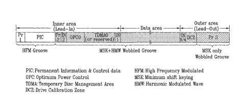
FIG. 1 is an optical disc structure capable of recording data
therein according to the present invention.
For the
convenience of description and better understanding of the
present invention, a single-layered BD-R/RE capable of
recording data therein is shown in FIG. 1.
Referring to FIG. 1, the optical disc sequentially includes
an inner area, a data area, and an outer area on the basis of
a disc inner area. A specific area contained in each of the
inner area and the outer area is used as either a recording
area for recording disc management information or a test area.
The data area records actual user data therein.
A detailed description of the inner area and the outer area
will hereinafter be described. The inner area includes a PIC
(Permanent Information & Control data) area, an OPC area, and
two information areas (i.e., info-areas) IN1 and IN2.
The
PIC area records disc management information as an embossed
HFM (High Frequency Modulated) signal. The OPC area serving
as a test area is adapted to perform the OPC process. The
info-areas INI and IN2 record various disc management
information including a Defect Management Area (DMA).
CA 02562359 2006-10-06
WO 2006/031041 9
PCT/KR2005/003003
In association with the above-mentioned description, a write-
once BD-R further includes a Temporary Disc Management Area
(TDMA) adjacent to the OPC area, but a BD-RE includes a
reserved area in the vicinity of the OPC area. The reserved
area acts as a spare area to be used later. The outer area
includes two other info-areas IN3 and IN4.
Protection zones Pr1 and Pr2 for disc protection are included
in the inner area, and a protection zone Pr3 for disc
protection is included in the outer area.
Specifically, a
protection area located at the innermost disc area of the
inner area is referred to as a first protection zone "Prl".
A protection area located at the outermost disc area of the
outer area is referred to as a third protection zone "Pr3".
A protection area located between the PIC area and the info-
area IN2 in the inner area is referred to as a second
protection zone "Pr2".
Particularly, the second protection
area "Pr2" is indicative of a changeover area between an
embossed PIC area and a recordable area, and is referred to
as a "buffer zone for changeover".
The BD-R/RE according to the present invention records data
in a groove part in a recording layer composed of a land part
and the groove part.
The groove part is composed of an HFM-
groove and a wobbled groove.
According to a variety of modulation schemes, the wobbled
groove is classified into an MSK+HMW modulation groove, and
CA 02562359 2006-10-06
WO 2006/031041 10
PCT/KR2005/003003
an MSK (Minimum Shift Keying) modulation groove. The MSK is
indicative of an acronym of a Minimum Shift Keying, and the
HMW is indicative of an acronym of a Harmonic Modulated Wave.
Particularly, the wobbled groove is configured in the form of
a wobbled shape using a modulation method associated with a
sinusoidal wave in a groove contained in a recording layer.
The optical recording/reproducing device can read address
information (i.e., ADIP: Address In Pre-groove) of a
corresponding groove and general disc information using the
above-mentioned wobbled shaped. A
detailed description
thereof will hereinafter be described with reference to FIGS.
5-8.
The above-mentioned modulation method is differently applied
to individual areas contained in the disc according to unique
characteristics of the areas. The Prl area and the PIC area
contained in the inner area are configured in the form of the
HFM-groove.
The Pr3 area contained in the outer area is
configured in the form of the wobbled groove to which only
the MSK modulation is applied. Excepting the above-mentioned
areas, the inner area, the outer area, and the data area are
configured in the form of a wobbled groove to which the
MSK+HMW modulation is applied.
FIG. 2 is a single-layered optical disc structure capable of
recording data therein according to the present invention.
Compared with FIG. 1, the single-layered optical disc
CA 02562359 2006-10-06
WO 2006/031041 11
PCT/KR2005/003003
structure shown in FIG. 2 further includes a Drive
Calibration Zone (DCZ) area in the outer area. The following
description will be mainly disclosed on the basis of the DCZ
area, and the remaining parts other than the DCZ area are
equal to those of FIG. 1, such that its detailed description
will herein be omitted for the convenience of description.
As stated above, the DCZ area is indicative of a test zone
where the optical recording/reproducing device can perform a
disc test for various purposes. Typically, the OPC process
can be performed in the DCZ area in the same manner as in the
OPC area acting as another test zone. It is obvious to those
skilled in the art that not only the OPC process but also
another test can be performed in the DCZ area, and it should
be noted that the present invention is not limited to the
above-mentioned example and is applicable to other examples
as necessary.
Compared with FIG. 1, the DCZ area shown in FIG. 2 is
physically included in the outer area. Therefore, the Pr3
area of FIG. 2 is less than the Pr3 area of FIG. 1 by a
predetermined size corresponding to an additionally-assigned
DCZ area. It is preferable that the DCZ area be less than
the OPC area (i.e., 2048 clusters) contained in the inner
area. For example, the DCZ area is assigned 512 clusters.
The above-mentioned additionally-assigned DCZ area uses the
MSK+HMW modulation method, in which the MSK modulation and
CA 02562359 2006-10-06
WO 2006/031041 12
PCT/KR2005/003003
the HMW modulation are mixed, in the same manner as in the
OPC area of the inner area and the data area. In other words,
a newly-assigned DCZ area is adapted to record/reproduce test
data. In order to correctly record the test data, reliable
address information (i.e., ADIP) must be guaranteed in the
same manner as in the general data area.
FIGS. 3a-3b are dual-layered optical disc structures capable
of recording data therein according to a preferred embodiment
of the present invention. A dual-layered BD-RE is shown in
FIG. 3a. A dual-layered BD-R capable of recording data
therein is shown in FIG. 3b. In association with the above-
mentioned description, one of two recording layers is
referred to as a "Layer() (L0)", and the other one is referred
to as a "Layerl (L1)".
As shown in FIG. 3a, individual recording layers have the
same structure in the dual-layered BD-RE according to the
present invention. The outer area of the recording layer LO
includes the DCZ area DCZO, and the outer area of the
recording layer L1 includes the DCZ area DCZ1. The MSK+HMW
modulation method in which the MSK modulation and the HMW
modulation are mixed is applied to the DCZ areas DCZO and
DCZ1 in the same manner as in the data area.
As can be seen from FIG. 3b, the write-once dual-layered BD-R
according to the present invention includes DCZ areas in
outer areas of individual recording layers LO and Li. The
CA 02562359 2006-10-06
WO 2006/031041 13
PCT/KR2005/003003
DCZ areas DCZO and DCZ1 uses the MSK HMW modulation method in
which the MSK modulation and the HMW modulation are mixed in
the same manner as in the data area.
Compared with the BD-RE shown in FIG. 3a. the write-once BD-R
shown in FIG. 3b requires many more management information
recording areas due to write-once characteristics, such that
a Temporary Disc Management Area (TDMA) is added to the inner
area, and the inner area of the second recording layer L1
includes the OPC area (OPC1) instead of the PIC area embossed
by the HFM.
In association with the above-mentioned description, the DCZ
area of the present invention is more efficiently available
for the write-once BD-R shown in FIG. 3b. In more detail,
the write-once BD-R requires many more management information
recording layers due to the write-once characteristics as
previously stated, such that it uses a DCZ area as a new test
area capable of substituting for the OPC area of the inner
area, and obviates the problem that data is no longer
recorded in the write-once BD-R due to a shortage of the OPC
area.
FIGS. 4a-4b are dual-layered optical disc structures capable
of recording data therein according to another preferred
embodiment of the present invention. A method for assigning
the DCZ area in individual recording layers is shown in FIGS.
4a-4b.
CA 02562359 2006-10-06
WO 2006/031041 14
PCT/KR2005/003003
In association with the above-mentioned description, although
FIGS. 4a--4b exemplarily show the write-once recordable disc
(e.g., a BD-R) for the convenience of description, technical
ideas of the present invention can be applied to the
rewritable disc (e.g., BD-RE) as described above.
As shown in FIG. 4a, when assigning the DCZ areas DCZO and
DCZ1 to individual outer areas of individual recording layers,
the DCZ areas DCZO and DCZ1 are not physically located at the
same position on the basis of a progression direction of an
optical beam.
In other words, provided that the DCZ areas are used for the
OPC process in the same manner as in the OPC area of the
inner area, a predetermined power value is gradually used for
the OPC process in the direction from high power to low power
or in the direction from low power to high power, or a power
value contained in a predetermined range on the basis of a
reference power is used for the OPC process.
Provided that DCZ areas DCZO and DCZ1 are physically located
at the same position on the basis of a progression direction
of an optical beam between recording layers adjacent to each
other, the probability of generating light-beam interference
even in the DCZ area (e.g., DCZ1) contained in a neighboring
recording layer other than an actually-used DCZ area (e.g.,
DCZO) is increased, resulting in the occurrence of a negative
influence upon a process for calculating an optical writing
CA 02562359 2006-10-06
WO 2006/031041 15
PCT/KR2005/003003
power using the OPC process. In this way, the OPC areas OPCO
and OPC1 contained in the inner areas are not physically
located at the same position on the basis of a progression
direction of an optical beam.
Therefore, the outer area of the second recording layer
further includes a buffer area located at the same position
as that of the DCZ area (DCZO) of the first recording layer
on the basis of a progression direction of an optical beam,
and the DCZ area (DCZ1) is then allocated in an outer
direction. Needless to say, individual outer-area allocation
methods of the first recording layer LO and the second
recording layer L1 can be performed in either order. For
example, the buffer area may be added to the outer area of
the first recording layer LO at the same position as that of
the DCZ area (DCZ1) of the second recording layer L1 on the
basis of a progression direction of the light or optical beam,
and the DCZ area (DCZO) may also be allocated in the outer
direction.
In association with the above-mentioned description, the DCZ
areas (DCZO and DCZ1) use the MZK+HMW modulation method in
which the MSK modulation and the HMW modulation are mixed in
the same manner as in the data area.
As can be seen from FIG. 4b, the DCZ area is characterized in
that it is allocated to not only outer areas of ip.dividual
recording layers but also a neighboring data area. In other
CA 02562359 2006-10-06
WO 2006/031041 16
PCT/KR2005/003003
words, the recording layer is classified into a first-type
recording layer (e.g., L1) and a second-type recording layer
(e.g., LO).
The DCZ area (DCZ1) is contained in the outer
area of the first-type recording layer, the DCZ area (DCZO)
is contained in the data area adjacent to the outer area in
the second-type recording layer, and the first-type recording
layer and the second-type recording layer are alternately
included in the optical disc.
FIGS. 5--8 are graphs illustrating a modulation method
according to the present invention.
FIG. 5 shows the MSK modulation method.
Particularly, the
Pr3 area (i.e., protection zone 3) contained in the outer
area is formed by only the MSK modulation.
The MSK modulation method is implemented by performing a
cosine transform at a wobble frequency f10b as shown in FIG. 5.
A general wobble is referred to as a "monotone wobble (MW)",
and three wobbles generated by changing the wobble frequency
fwob and a cosine code are each referred to as an "MSK Mark
wobbled (MM)".
FIG. 6 shows the HMW modulation method.
Particularly, the
OPC area contained in the inner area, and the DCZ area and
the data area contained in the outer area are formed by the
MSK+HMW modulation method in which the HMW modulation and the
MSK modulation are mixed.
CA 02562359 2006-10-06
WO 2006/031041 17
PCT/KR2005/003003
In association with the above-mentioned description, as shown
in FIG. 6, the HMW modulation method is implemented by the
cosine transform performed at a first wobble frequency fwob
and a sine transform performed at a second wobble frequency
2* fwob = If
the sine transform has a positive(+) code, the
value of 1 is determined.
If the sine transform has a
negative(-) code, the value of 0 is determined. The wobble
formed by the above-mentioned method is referred to as a
"sawtooth wobble (STW)".
The sawtooth wobble (STW) of the
value of 1 is referred to as an STW("1").
The sawtooth
wobble (STW) of the value of 0 is referred to as an STW("0").
FIG. 7 shows a method for identifying an ADIP unit using the
MSK+HMW modulation method. As can be seen from FIG. 7, a
single ADIP unit includes 56 wobbles. Three head wobbles of
all ADIP units are each composed of an MSK mark (MM). The
ADIP units are classified into the following units according
to wobble types.
In other words, the ADIP unit composed of "1 MM + 53 MW" is
referred to as a monotone unit, and the ADIP unit composed of
"1 MM + 15MW + 37 STW("0") + 1MW" is referred to as a
reference unit.
The ADIP unit composed of "1 MM + 13 MW + 1 MM + 7 MW + 1 MM
+ 27 MW" is referred to as "sync_O unit".
The ADIP unit
composed of "1 MM + 15 MW + 1 MM + 7 MW + 1 MM + 25 MW" is
referred to as "sync_1 unit". The ADIP unit composed of "1
CA 02562359 2006-10-06
WO 2006/031041 18
PCT/KR2005/003003
MM + 17 MW + 1 MM + 7 MW + 1 MM + 23 MW" is referred to as
"sync _2 unit". The ADIP unit composed of "1 MM + 19 MW + 1
MM + 7 MW + 1 MM + 21 MW" is referred to as "sync _3 unit".
The ADIP unit composed of "1 MM + 9 MW + 1 MM + 3 MW + 37
STW("0") is referred to as "data _1 unit". The ADIP unit
composed of "1 MM + 11 MW + 1 MM + 1 MW + 37 STW("1") + 1 MW"
is referred to as "data 0 unit". In other words, if "data 1
unit" is determined, the value of 1 is established.
If
"data 0 unit" is determined, the value of 0 is established.
FIG. 8 shows a method for constructing a single ADIP word
composed of 83 ADIP units shown in FIG. 7.
As can be seen from FIG. 8, the 9 head ADIP units of the ADIP
word sequentially include "monotone unit", "sync _O unit",
"monotone unit", "sync_1 unit", "monotone unit", "sync _2
unit", "monotone unit", "sync _3 unit", and "reference unit".
ADIP units from 10-th ADIP unit (i.e., ADIP unit number . 9)
to 83-rd ADIP unit (i.e., ADIP unit number = 82) are each
composed of either "data_O unit" or "data_1 unit" shown in
FIG. 7. Five units are formed by combining the ADIP units by
four bits, such that the above-mentioned units are referred
to as "ADIP codeword nibble numbers (c0--c14)".
A physical address (i.e., Physical ADIP Address "PAA") of a
corresponding wobble and auxiliary data are recorded in the
above-mentioned ADIP codeword nibble number (c0--c14).
The
optical recording/reproducing device reads the single ADIP
CA 02562359 2006-10-06
WO 2006/031041 19
PCT/KR2005/003003
word, such that it can recognize the PAA position of a
current disc.
Technical ideas shown in FIGS. 5--8 are applied to all areas
to which the MSK+HMW modulation method is applied. Therefore,
the MSK+HMW modulation method is applied to even the DCZ area
contained in the outer area.
The reason why the MSK+HMW modulation method is applied to
the DCZ area is as follows. The DCZ area is indicative of a
specific area for recording actual test data. Therefore, if
only the MSK modulation method is applied to the DCZ area in
the same manner as in the Pr3 area (i.e., protection zone 3),
the sawtooth wobble (STW) caused by the HMW modulation is not
used, such that "monotone unit" and "reference unit" from
among ADIP units shown in FIG. 7 cannot be distinguished from
each other, and an unexpected error may occur in
distinguishing "data _1 unit" and "data _O unit".
Preferably, the DCZ area may use the MSK+HMW modulation
method to prevent the occurrence of the unexpected error,
differently from the Pr3 area (i.e., protection zone 3) to
which only the MSK modulation method is applied.
The present invention can be applied to a recording medium
provided when there are a plurality of layers acting as
recording layers.
CA 02562359 2006-10-06
WO 2006/031041 20
PCT/KR2005/003003
FIG. 9 is a conceptual diagram illustrating a method for
recording management information capable of managing the OPC
area and the DCZ area in an optical disc.
In more detail, a DMA (Disc Management Area) and/or a TDMA
(Temporary DMA) are included in the inner area and/or outer
area of the optical disc. Management information of the OPC
area and the DCZ area is recorded in the TDMA or DMA.
In other words, the management information is recorded in the
TDMA in the case of a write-once recordable disc such as BD-R,
and the management information is recorded in the DMA in the
case of a rewritable disc such as a BD-RE. As shown in FIG.
1, the DMA is generally included in info-areas IN1 and IN2 of
the inner area or other info-areas IN3 and IN4 of the outer
area.
In association with the above-mentioned description, the
management information of the OPC area and the DCZ area may
include information indicative of positions of the OPC area
and the DCZ area for every recording layer of the disc, for
example, start address information and/or end address
information (i.e., "OPCs location info" and "DCZs location
info"), and information indicative of current available
positions in individual OPC and DCZ areas (i.e., "Next
available PSN in each OPC" and "Next available PSN in each
DCZ").
CA 02562359 2006-10-06
WO 2006/031041 21
PCT/KR2005/003003
Therefore, if the disc is seated in the optical
recording/reproducing device, the optical
recording/reproducing device reads management information of
the OPC area and the DCZ area contained in the TDMA or DMA.
Therefore, the optical recording/reproducing device
recognizes position information of the OPC area contained in
the disc and other position information of the available OPC
area, and recognizes position information of the DCZ area and
other position information of the available DCZ area, such
that it can perform the OPC process at the recognized
positions.
It is obvious to those skilled in the art that management
information associated with the OPC area and the DCZ area are
equally applied to all optical discs shown in FIGS. 2--4b.
FIG. 10 is a conceptual diagram illustrating a method for
performing an OPC process according to the present invention.
A recording-medium tracking direction of the optical
recording/reproducing device in the recording medium is
determined to be a PSN increasing direction along which the
PSN is increased in the direction from a low PSN (Physical
Section Number) to a high PSN. A direction for performing the
OPC process in the recording medium is determined to be a PSN
reducing direction along which the PSN is decreased in the
direction from a high PSN to a low PSN.
CA 02562359 2006-10-06
WO 2006/031041 22
PCT/KR2005/003003
A recording direction after the OPC process is determined to
be a PSN increasing direction from a low PSN to a high PSN in
the same manner as in the tracking direction.
In association with the above-mentioned description, a unit
for recording data by performing the OPC process in the OPC
area may exactly correspond to a 1-cluster unit whereas a
unit for recording data in a data area of the recording
medium is a 1-cluster unit. However, a data recording area
acquired by the OPC process may be less than the 1 cluster,
may also be larger than the 1 cluster.
In other words, a unit of data recorded to perform the OPC
process is equal to an Address Unit Number (AUN). The AUN is
indicative of address information used during a data
recording time. It is obvious to those skilled in the art
that an unused OPC area acting as a previous area formed
prior to the data recording does not include the above-
mentioned AIM information.
In this case, the AUN acts as a unit having a range less than
that of the cluster, and a single cluster includes 16 AUNs.
In more detail, a single OPC process performing length is
selected by the optical recording/reproducing device, and is
not limited by the number of physical clusters.
FIG. 10 shows a specific case in which three OPC processes
are performed. In more detail, FIG. 10 shows a plurality of
CA 02562359 2006-10-06
W02006/031041 23
PCT/KR2005/003003
parts, each of which performs the OPC process, and a
plurality of OPC markers for identifying individual parts.
A part for performing a first OPC process is denoted by
"Cluster #P+1", and includes a first part denoted by "OPC #M"
and a second part denoted by "OPC Marker #M". The "OPC #M"
part records data therein, and the "OPC Marker #M" part
identifies the "OPC #M" part.
A part for performing a second OPC process includes "Cluster
#P", "Cluster #N", and some parts of "Cluster #N-1". A part
denoted by "OPC #M+1" records data therein, and the "OPC
Marker #M+1" identifies the "OPC #M+1" part.
A part for performing a third OPC process is composed of some
parts of the "Cluster #N-1" part. In more detail, the part
for performing the third OPC process includes "OPC #M+2 and
"OPC Marker #M+2". The "OPC #M+2" part records data therein,
and the "OPC Marker #M+2" part identifies the "OPC #M+2" part.
In this case, "Cluster 4tN-2" and some parts of the "Cluster
#N-1" part positioned prior to the "OPC Marker #M+2" part
serve as unused cluster areas.
In association with the above-mentioned description, the
distance between two successive OPC markers from among OPC
markers capable of identifying data recording areas
associated with the OPC process is equal to or less than a
predetermined distance corresponding to 16 clusters. For
example, in order to satisfy the above-mentioned requirements
CA 02562359 2006-10-06
WO 2006/031041 24
PCT/KR2005/003003
in the OPC process requiring at least 16 clusters, the OPC
marker must be inserted into the OPC process. In this case,
the above-mentioned OPC marker must have a predetermined
length corresponding to at least 868 NWLs (Nominal Wobble
Lengths).
The "OPC #M" part shown in FIG. 10 occupies a single cluster
(i.e., 1 cluster) in the OPC area.
The "OPC #M+1" part
occupies a predetermined area larger than the 1 cluster in
the OPC area. The "OPC #M+2" part occupies a predetermined
area less than the 1 cluster in the OPC area. It
can be
understood that the OPC process is performed in unit smaller
than cluster unit, for example in AUN unit.
FIG. 11 is a conceptual diagram illustrating a method for
searching for an OPC start position according to the present
invention.
The 1 cluster from among the OPC area is shown in FIG. 11.
The 1 cluster corresponds to 13944 wobbles, 249 ADIP units,
498 sync frames and 3 ADIP words. In association with the
above-mentioned description, the 1 ADIP word includes 83 ADIP
units, and the ADIP unit includes 56 wobbles. The 1 cluster
includes 16 AUNs. In this case, the wobble is indicative of
a NWL (Nominal Wobble Length).
For example, a pre-used (i.e., last used) OPC a'rea (i.e.,
AUN6¨ AUN15) contained in the 1 cluster is indicative of 10
AUNs (Address Unit Numbers), and an unused OPC area is
CA 02562359 2006-10-06
WO 2006/031041 25
PCT/KR2005/003003
indicative of 6 AUNs from AUNO to AUN5. The AUN 6 in the last
used OPC area can be detected by inserting the OPC marker in
front of the AUN 6 as described in FIG.10. The OPC performing
size indicative of a predetermined size required for a
current OPC process is predetermined by the optical
recording/reproducing device, and can be established in
various ways. It is assumed that the OPC performing size is
equal to 4 AUNs from AUN2 to AUN5.
Therefore, if a user desires to perform a new OPC process
from a predetermined position of the AUN2, the user must
search for a physical position corresponding to the AUN2.
Therefore, in order to determine the OPC start position using
a wobble count process, there is a need for a wobble-count
reference position to be found. If a predetermined reference
wobble is detected in a detecting process of the optical
recording/reproducing device, the detected reference wobble
is considered to be a wobble-count reference position.
Preferably, the wobble-count reference position may be equal
to a start position of the cluster.
The above-mentioned cluster start position indicative of the
wobble-count reference position is identical with a start
position of the ADIP word. Referring to FIGS. 7--8, the 9
head ADIP units of the ADIP word sequentially correspond to
"monotone unit", "sync _O unit", "monotone unit", "sync _1
unit", "monotone unit", "sync_2 unit", "monotone unit",
CA 02562359 2006-10-06
WO 2006/031041 26
PCT/KR2005/003003
"sync _3 unit", and "reference unit".
Therefore, if the 9
head ADIP units of the ADIP word are sequentially detected or
the first "monotone unit" is detected during a search time of
the optical recording/reproducing device, the ADIP-word start
position is established.
In other words, the cluster start
position is considered to be a wobble-count reference
position.
According to another example of the above-mentioned reference
position, it is preferable that the ADIP-word start position
contained in the 1 cluster be considered to be the wobble-
count reference position.
In other words, the 1 cluster includes three ADIP words. In
this case, if the next OPC start position is in the "ADIP
Word 1" area or the "ADIP Word 2" area, the 9 head ADIP units
of the ADIP word indicative of a start position of the "ADIP
Word 2" area sequentially correspond to "monotone unit",
"sync _O unit", "monotone unit", "sync _1 unit", "monotone
unit", "sync _1 unit", "monotone unit",
"sync_2 unit",
"monotone unit", "sync _3 unit", and "reference unit".
Otherwise, if the first "monotone unit" is detected, the a
start position of "ADIP Word 1" area or a start position of
the "ADIP Word 2" area is determined to be a wobble-count
reference position, such that the number of wobbles can be
counted.
CA 02562359 2006-10-06
WO 2006/031041 27
PCT/KR2005/003003
Therefore, if the wobble-count reference position is
determined, and size information a pre-used OPC area acting
as a recorded area and size information of an OPC area
required for a current OPC process are recognized, the
optical recording/reproducing device counts the number of
wobbles at the wobble-count reference position, and searches
for an OPC start position desired by a drive.
According to the preferred embodiment shown in FIG. 11, a
drive counters wobbles of two AUNs from ADNO to AUN1. A
single AUN corresponds to the length of 868 wobbles.
Therefore, two AUNs correspond to the length of 868*2 wobbles,
the drive counts the number of 868*2 wobbles to determine an
OPC start position, and performs the OPC process in order to
calculate an optimum write power at the determined OPC start
position.
FIG. 12 is a block diagram illustrating an optical
recording/reproducing device according to the present
invention.
Referring to FIG. 12, the optical recording/reproducing
device includes a recording/reproducing unit 20 for
recording/reproducing data in/from an optical disc, and a
controller 12 for controlling the recording/reproducing unit
20.
The recording/reproducing unit 20 includes a pickup unit 11,
a signal processor 13, a servo unit 14, a memory 15, and a
CA 02562359 2006-10-06
WO 2006/031041 28
PCT/KR2005/003003
microprocessor 16. The pickup unit 11 directly records data
in the optical disc, or reads data recorded in the optical
disc. The signal processor 13 receives a signal read from
the pickup unit 11, restores the received signal to a desired
signal value, or modulates a signal to be recorded into
another signal recorded in the optical disc, such that it
transmits the recovered or modulated result. The servo unit
14 controls operations of the pickup unit 11, such that it
correctly reads a desired signal from the optical disc, and
correctly records the signal in the optical disc. The memory
temporarily stores not only management information
including PIC data but also data.
The microprocessor 16
controls overall operations of the above-mentioned components.
The above-mentioned recording/reproducing unit 20 performs a
15 predetermined test in a test area of a recording medium, such
that it calculates an optimum write power.
The
recording/reproducing unit 20 records the calculated optimum
write power, and records data in the recording medium at the
calculated optimum write power upon receiving a recording
command from the controller 12.
The recording/reproducing unit 20 determines whether the
optical disc acting as the recording medium is formatted in
an initialization process.
If the optical disc is not
formatted, the recording/reproducing unit 20 performs the
formatting of the optical disc.
CA 02562359 2006-10-06
WO 2006/031041 2 9
PCT/KR2005/003003
In association with the above-mentioned description, the
optical recording/reproducing device composed of only the
recording/reproducing unit 10 is referred to as a drive, and
is generally used as a peripheral device of a computer.
The controller 12 controls operations of overall constituent
components. In association with the present invention, the
controller 12 refers to a user command by interfacing with a
user, and transmits a recording/reproducing command capable
of recording/reproducing data in/from the optical disc to the
recording/reproducing unit 20.
The decoder 17 decodes a signal read from the optical disc
upon receiving a control signal from the controller 12,
restores the decoded signal to desired information, and
transmits the restored signal to the user.
The encoder 18 receives a control signal from the controller
12 to record a desired signal in the optical disc, converts
the received signal into a specific-format signal (e.g., an
MPEG2 transport stream), and transmits the specific-format
signal to the signal processor 13.
A method for recording data in the recording medium using the
above-mentioned optical recording/reproducing device
according to the present invention will hereinafter be
described with reference to FIGS. 13-16.
FIG. 13 shows a method for recording data in the recording
medium using the optical recording/reproducing device in
CA 02562359 2006-10-06
WO 2006/031041 30
PCT/KR2005/003003
accordance with a first preferred embodiment of the present
invention. Particularly, a method for calculating the optimum
write power is shown in FIG. 13.
Referring to FIG. 13, if the optical disc of a physical
structure including the OPC area and the DCZ area is seated
in the optical recording/reproducing device, the
microprocessor 16 of the recording/reproducing unit 20
controls operations of the pickup unit 11 using the servo
unit 14, it reads OPC-area management information and the
DCZ-area management information (e.g., "OPC location info",
"Next available PSN of OPC", "DCZ location info.", and "Next
available PSN of DCZ") recorded in the TDMA or DMA of the
seated disc at step S11, and temporarily stores the OPC area
management information and the DCZ area management
information in the memory 15.
The microprocessor 16 recognizes a correct position, at which
the OPC process is to be performed, by referring to the
above-mentioned management information at step S12. The
microprocessor 16 receives a command for performing the OPC
process at step S13, and performs the OPC process at the
above position recognized by the management information.
Particularly, the OPC process is performed in the OPC area
and the DCZ area, such that an optimum write power to be
available for the seated optical disc is calculated at steps
S14 and S16. If the optimum write power has been calculated
CA 02562359 2006-10-06
WO 2006/031041 31
PCT/KR2005/003003
at steps S14 and S16, the microprocessor 16 updates the "next
available PSN of OPC" information and the "next available PSN
of DCZ" information as the management information associated
with the next OPC position at steps S15 and S17.
Particularly, the MSK4EMW modulation method is applied to
both the OPC area capable of performing the OPC process and
the DCZ area, such that ADIP information can be stably read
from a groove track. A physical location corresponding to the
OPC-area management information and the DCZ-area management
information is recognized from the read ADIP information at
step S12.
Upon receiving a command for recording data in a
corresponding disc from the controller 12, the
recording/reproducing unit 20 performs the above recording
command using the calculated optimum write power, and a
detailed description thereof will hereinafter be described
with reference to FIG. 14.
FIG. 14 shows a method for recording data in the recording
medium using the optical recording/reproducing device in
accordance with a second preferred embodiment of the present
invention.
Referring to FIG. 14, the microprocessor 16 contained in the
recording/reproducing unit 20 receives a recording command
from the controller 12. The recording command is composed of
CA 02562359 2006-10-06
WO 2006/031041 32
PCT/KR2005/003003
recording data and position information to be recorded in the
disc at step S21.
Therefore, the microprocessor 16 selects an optimum write
power, at which data is to be recorded, on the basis of
recording position information contained in the recording
command at step S22. For example, if the recording position
is in the vicinity of the inner area of the disc, the
microprocessor 16 uses the optimum write power (i.e., the
writing power calculated at step S14) calculated at the OPC
area at step S23. If the recording position is in the
vicinity of the outer area of the disc, the microprocessor 16
uses the optimum write power (i.e., the writing power
calculated at step S16) calculated at the DCZ area at step
S23.
FIG. 15 shows a method for recording data in the recording
medium using the optical recording/reproducing device in
accordance with a third preferred embodiment of the present
invention.
Referring to FIG. 15, if the optical disc of a physical
structure including the OPC area and/or the DCZ area is
seated in the optical recording/reproducing device at step
S31, the microprocessor 16 of the recording/reproducing unit
20 contained in the optical recording/reproducing device
controls operations of the pickup unit 11 using the servo
unit 14, it reads information from the seated optical disc,
CA 02562359 2006-10-06
WO 2006/031041 3 3
PCT/KR2005/003003
and determines whether the optical disc is formatted in a
disc initialization process at step S32.
If it is determined that the optical disc is formatted at
step S32, the microprocessor 16 performs the OPC process to
calculate an optimum write power at step S33.
A variety of preferred embodiments associated with a method
for performing the OPC process in a dual-layered optical disc
composed of two layers "Layer0(L0)" and "Layerl(L1)" will
hereinafter be described.
According to the first preferred embodiment of the present
invention, the OPC process for calculating an optimum write
power of the layer LO is performed using the OPCO area and
the DCZO area, and at the same time another OPC process for
calculating an optimum write power of the layer Ll using the
OPC1 area and the DCZ1 area is performed. In this case, the
controller 12 for receiving a command from the user can
determine whether which one of test areas will firstly
perform the OPC process.
In other words, according to the above-mentioned first
preferred embodiment of the present invention, an optimum
write power of the test area is calculated, the calculated
information is recorded in the test area, and the calculated
optimum write power is used when data is recorded in the data
area.
CA 02562359 2006-10-06
WO 2006/031041 34
PCT/KR2005/003003
According to a second preferred embodiment of the present
invention, the OPC process for calculating an optimum write
power is performed using an OPCO area and a DCZO area, which
act as test areas of the layer LO. Upon receiving a user
recording command from the controller 12, the OPC process for
calculating an optimum write power when data is recorded in
the layer L1 is performed in the OPC1 area acting as a test
area of the layer L1 and the DCZ1 area.
In this case, the controller 12 for receiving a command from
the user can determine whether which one of test areas
composed of the OPCO area and the DCZO area will firstly
perform the OPC process.
According to a third preferred embodiment of the present
invention, the OPC process for calculating an optimum write
power is performed using both the OPCO area acting as a test
area of the inner area of the optical disc and the OPC1 area
acting as a test area of the inner area. Upon receiving a
user recording command from the controller 12, the OPC
process for calculating an optimum write power when data is
recorded in the optical disc is performed in the DCZO area
acting as a test area of the outer area 0 of the optical disc
and the DCZ1 area acting as a test area of the outer area 1.
In this case, the controller 12 for receiving a command from
the user can determine whether which one of test areas
CA 02562359 2006-10-06
WO 2006/031041 35
PCT/KR2005/003003
composed of the OPCO area and the OPC1 area will firstly
perform the OPC process.
According to a fourth preferred embodiment of the present
invention, the OPC process for calculating an optimum write
power is performed using the OPCO area acting as a test area
of the inner area of the optical disc. Upon receiving a user
recording command from the controller 12, the OPC process for
calculating an optimum write power when data is recorded in
the optical disc is performed in three areas, i.e., the DCZO
area acting as a test area of the outer area 0 of the optical
disc, and the OPC1 and DCZ1 areas acting as test areas of the
layer L1.
In association with the above-mentioned description, if the
optical recording/reproducing device records data in a disc
acting as a recording medium according to the second
preferred embodiment of the present invention, the layer LO
performs the OPC process to calculate the optimum write power,
sudh that it reads data using the calculated optimum write
power according to position information of a data area where
data is to be recorded. The layer L1 performs a data record
operation according to position information of a data area
where data is to be recorded. In more detail, when data is
recorded in the vicinity of the inner area of the data area
of the optical disc, the layer L1 employs the optimum write
power which has been calculated by performing the OPC process
CA 02562359 2006-10-06
WO 2006/031041 36
PCT/KR2005/003003
in the OPC1 area contained in the inner area 1. When data is
recorded in the vicinity of the outer area of the data area
of the optical disc, the layer L1 employs the optimum write
power which has been calculated by performing the OPC process
in the DCZ1 area contained in the outer area 1. In this way,
the layer L1 can recording data using one of the optimum
write powers according to data recording positions.
Although the above-mentioned description uses the second
preferred embodiment as an example of various methods capable
of performing the OPC process, it is obvious to those skilled
in the art that the above-mentioned description can also be
applied to other preferred embodiments, i.e., the first
preferred embodiment, the third preferred embodiment, and the
fourth preferred embodiment.
The method for performing the OPC process when the disc
acting as a recording medium is a dual-layered disc has been
disclosed in the above-mentioned description. If the above-
mentioned disc is a single-layered disc, only one recording
layer is used as the recording medium. Therefore, if a first
case in which the OPC process is performed in the OPCO and
DCZ areas acting as test areas, a second case in which the
OPC process is performed in only the OPCO area, and a third
case in which the OPC process is performed in the DCZ area
require the OPC process during a disc use time, i.e., if a
user recording command is received in the dual-layered
CA 02562359 2006-10-06
WO 2006/031041 3 7
PCT/KR2005/003003
optical disc, the first case, the second case, and the third
case performs the OPC process to calculate an optimum write
power when data is recorded in the optical disc.
It is obvious to those skilled in the art that the above-
mentioned method for performing the OPC process is applied to
at least one layer acting as a recording layer.
Provided that the optical disc has used a test area for a
pre-test during the OPC process at step S33, the OPC start
position must be detected to perform the OPC process in an
unused test area. In this case, it is preferable that the
OPC start position be found using the method shown in FIG. 11.
If the disc is not formatted at step S32, the
recording/reproducing unit 20 determines the presence or
absence of an external format command at step S34.
If the format command is received from the controller 12 at
step S34, the recording/reproducing unit 20 performs the OPC
process to calculate the optimum write power simultaneously
with performing the format process at step S35.
It is preferable that the method for performing the OPC
process at step S35 be performed in the same manner as in the
above-mentioned preferred embodiments described at step 533.
The method for performing the OPC process simultaneously with
performing the format process is described at step S35, such
that there is no test for calculating the optimum write power
CA 02562359 2006-10-06
WO 2006/031041 38
PCT/KR2005/003003
to recording data at step S35. In this case, the OPC process
is performed at an available position of the test area.
The OPC process is performed at steps S33 and S35, and the
calculated optimum write power is recorded in the test area
at step S36.
Therefore, if a user's recording/reproducing command is
transmitted to the recording/reproducing unit 20 via the
controller 12, the recording/reproducing unit 20 records data
in the disc or reproduces information recorded in the disc at
step S37.
In association with the above-mentioned description, it is
preferable that a test for calculating the optimum write
power in only the OPC area be performed in a recording medium
including the OPC area other than the DCZ area.
A method for recording data in a recording medium when the
optical recording/reproducing device does not immediately
perform the OPC process when the optical disc is seated in
the optical recording/reproducing device whereas the optical
disc has been formatted will hereinafter be described with
reference to FIG. 16.
Although the recording medium is seated in the optical
recording/reproducing device, the recording/reproducing unit
20 maintains a standby mode without forming the OPC process
at step S41.
CA 02562359 2006-10-06
WO 2006/031041 39
PCT/KR2005/003003
It is determined whether a recording command is received from
the controller 12 when the recording/reproducing unit 20 is
in the standby mode at step S42. If it is determined that
the recording command has been received from the controller
12 at step S42, the OPC process is performed in the test area
to perform a data recording operation, such that an optimum
write power is calculated at step S43. The calculated
optimum write power is recorded in the test area.
Data suitable for the recording command is recorded in the
data area of the recording medium using the calculated
optimum write power at step S44.
The present invention uses the optimum write power calculated
in the OPC area of the inner area when data is recorded in
the vicinity of the inner area of the data area of the disc.
When data is recorded in the vicinity of the outer area of
the data area of the optical disc, the present invention uses
the optimum write power calculated in the DCZ area of the
outer area. Therefore, the present invention can properly use
the optimum write power according to data recording positions.
In other words, the first optimum write power applied in the
vicinity of the inner area of the disc is acquired by the
result calculated in the OPC area, and the second optimum
write power applied in the vicinity of the outer area of the
disc is acquired by the result calculated in the DCZ area,
resulting in the prevention of a data recording error. In
CA 02562359 2006-10-06
WO 2006/031041 40
PCT/KR2005/003003
this case, the data recording error may occur when the same
writing power is applied to overall data areas during a
predetermined data recording time during which data is
recorded in a high-density disc such as a BD at high speed.
For another example, the first optimum write power calculated
in the OPC area and the second optimum write power calculated
in the DCZ area are not used in the example without any
change, but individual weights are applied to the first and
second optimum write powers according to data recording
positions to determine the last writing power. Otherwise, if
the data recording position is in the vicinity of the center
part of the data area, a mean value of the calculated optimum
write powers can also be applied to the present invention.
As apparent from the above description, a physical structure
including the OPC area and the DCZ area of a recording medium,
and a method and apparatus for recording/reproducing data
in/from the recording medium using the physical structure
according to the present invention can be applied to a method
for manufacturing a BD recently developed, and can
effectively record/reproduce data in/from the disc.
Industrial Applicability
It will be apparent to those skilled in the art that various
modifications and variations can be made in the present
invention without departing from the spirit or scope of the
CA 02562359 2006-10-06
WO 2006/031041 41
PCT/KR2005/003003
inventions. Thus, it is intended that the present invention
covers the modifications and variations of this invention
provided they come within the scope of the appended claims
and their equivalents.