Note: Descriptions are shown in the official language in which they were submitted.
CA 02562422 2006-10-10
WO 2005/097621 PCT/US2005/009772
-1-
HOUSING AND ACTUATING APPARATUS AND METHODS
ASSOCIATED THEREWITH
Technical Field
The present invention relates generally to housings that hold containers, and
more
particularly to housings that hold containers and actuators that actuate valve
apparatus to
dispense product from the container. '
Background
Various apparatus for dispensing product from a container or reservoir of
product
have been developed. Smrt U.S. Patent No. 5,287,998 discloses an actuator
fitted to a
container and including an axially extending passage therethrough for
discharging product.
The actuator includes a pair of wings that extend transversely from the
actuator. The
container may be moved axially within a device such that the wings bear
against a surface
defining a passage, thereby discharging product through the passage.
Brotspies et al. discloses a spray bottle grip used with a nasal spray bottle.
The
grip is coupled to a reciprocating nozzle of the spray bottle, and two arms
extend
downwardly along the spray bottle. The arms include finger flanges that
provide an
ergonomic means of reciprocating the nozzle to dispense product from the spray
bottle.
Haas U.S. Patent No. 3,318,492 discloses a disc-shaped actuator attached to a
nozzle of a container. A user may depress the actuator with her finger to
dispense product
from the container.
Scheindel et al. U.S. Patent No. 6,340,103 discloses a handle extending along
a
container body. When a user pulls the handle toward the container body, a
portion of the
handle pushes downwardly upon a nozzle portion of the container to dispense
product
from the container.
Micallef U.S. Patent No. 4,138,039 discloses a container having a vertically
reciprocating tubular pump. A cap is fitted to the container and includes an
actuator
button extending from a sidewall of the cap. Movement of the actuator button
in a
direction toward the sidewall of the cap is translated into perpendicular
reciprocating
movement of the pump.
CA 02562422 2008-08-13
WO ?005/097621 PCT/13S2005/009772
-2-
Other patents disclose devices having a container of product disposed at a
first end
of a rod and having a trigger mechanism at a second end of the rod wherein a
user may
actuate the container from a distance. Discharging product from a distance can
be an
advantage for many purposes, such as accessing hard-to-reach places or perhaps
for
discharging an insecticide into a hornet nest without placing oneself too
close to the nest.
Smrt U.S. Patent No. 5,518,148 discloses a device where an actuating rod has a
trigger on
a first end and a container on a second end. Pulling the trigger moves the
actuating rod
longitudinally such that the second end of the rod moves a bell crank, which
in turn,
moves an additional rod that actuates a valve on the container. Aberegg et al.
U.S. Patent
No. 6,551,001, assigned to the assignee of the present application and the
disclosure of
which is incorporated by reference herein, discloses a cleaning device having
a trigger at a
first end of a rod and a mop cleaning head and a container at a second end of
the rod.
Pulling the trigger moves a pivot link, which in turn actuates a valve of the
container,
thereby discharging product from the container onto the surface to be cleaned
by the mop
cleanin~; head.
Adams et al. U.S. Patent No. 5,358,147, assigned to the present assignee,
discloses
a container of air freshener inserted into a shroud. The shroud includes a
nozzle that is
fitted over a valve stem of the container. The combination of the container
and the shroud
is placed within a housing. When a user wishes to spray air freshener into
ambient air, the
user pushes the housing, which in turn pushes the shroud and the valve stem to
dispense the
air freshener out of the housing.
Summary of the Invention
In accordance with one aspect of the present invention, a combination includes
a
product container having a longitudinal dimension and a valve oriented to
discharge
product generally longitudinally therefrom. Valve actuating apparatus extends
laterally
from the valve in a direction transverse to the longitudinal dimension and
terminates at an
outer peripheral surface. A housing has a,wall that tapers to a discharge
opening, and the
discharge opening has a size larger than a radius of the container but smaller
than the
greatest lateral extent of the valve actuating apparatus. The outer peripheral
surface is
CA 02562422 2006-10-10
WO 2005/097621 PCT/US2005/009772
-3-
disposed in interfering relationship with the wall when the container is
disposed in the
housing.
A further aspect of the present invention comprehends an actuator cap having a
main wall that extends generally along an axial dimension thereof and has a
varying cross
sectional size. An actuator member extends transversely to the axial dimension
and ends
in an outer peripheral surface that extends laterally beyond a portion of the
main wall, but
does not extend beyond a greatest lateral extent of the main wall.
According to another aspect of the present invention, an actuator cap includes
a
main wall that extends generally along an axial dimension thereof and has a
varying cross
sectional size. An actuator member is movable relative to the main wall and
has an outer
peripheral surface extending laterally beyond the main wall at the axial
location of the
outer peripheral surface.
According to a further aspect of the present invention, an actuator cap
includes a
main wall having an axial dimension and tapering between first and second
ends. An
actuator member extends transversely to the axial dimension and ends in an
outer
peripheral surface that extends laterally beyond a portion of the main wall at
the axial
location of the outer peripheral surface. The actuator member is disposed
intermediate the
first and second ends.
A further aspect of the present invention comprehends a method of dispensing
including the step of selecting a container of product having a longitudinal
dimension, a
valve actuable to dispense product generally parallel to the longitudinal
dimension, and
valve actuating apparatus extending from the valve in a direction transverse
to the
container's longitudinal dimension and terminating at an outer peripheral
surface. A
housing is selected having a wall that reduces in cross sectional size to a
discharge
opening that has a size larger than a radius of the container. However, the
opening is
small enough so that the wall provides an interfering relationship with the
outer peripheral
surface when the container is placed into the housing. A relative movement of
the
container and the housing is provided in a direction along the longitudinal
dimension such
that the outer peripheral surface contacts a surface of the wall, thereby
displacing the valve
-30 -- actuating apparatus to-dispense product fromthe-housing:
CA 02562422 2006-10-10
WO 2005/097621 PCT/US2005/009772
-4-
A further aspect of the present invention envisions a method of providing
apparatus to an end user that includes the step of providing a container of
product having a
longitudinal dimension and valve actuating apparatus extending in a direction
transverse to
the longitudinal dimension and terminating at an outer peripheral surface. The
container is
delivered or caused to be delivered to the end user. The container and the
valve actuating
apparatus are identified as suitable for placement within a housing that has a
wall that
tapers to a discharge opening having a size larger than a radius of the
container but small
enough to provide an interfering relationship between the wall and the valve
actuating
apparatus. Product can be dispensed by moving the container and the housing
relative to
each other in a direction along the longitudinal dimension to displace the
valve actuating
apparatus against a surface of the wall.
Other aspects and advantages of the present invention will become apparent
upon
consideration of the following detailed description.
Brief Description of the Drawings
FIG. 1A is an exploded isometric view of a container and valve actuating
apparatus;
FIG. 1B is an exploded isometric view showing a container having a female-type
receiver valve;
FIG. 1C is an isometric view of valve actuating apparatus;
FIG. 1D is an isometric view of a valve stem having an arm extending
therefrom;
FIG. 2 is an exploded isometric view of a housing into which the container of
FIG.
1A may be placed;
FIG. 3 is a side elevational view of the housing of FIG. 2;
FIG. 4 is a sectional view taken generally along the lines 4-4 of FIG. 3
further
illustrating the container of FIG. 1 in elevation;
FIG. 5 is an enlarged fragmentary view of FIG. 4;
FIG. 5A is an enlarged sectional view taken generally along the lines 5A-5A of
FIG. 5;
FIG. 6 is a fragmentary exploded isometric view illustrating a nozzle that
may_be
fitted to a valve stem;
CA 02562422 2006-10-10
WO 2005/097621 PCT/US2005/009772
-5-
FIG. 7 is an enlarged bottom elevational view of the nozzle of FIG. 6;
FIG. 8 is a side elevational view showing a rod and trigger mechanism in
combination with the housing of FIG. 3;
FIG. 9 is a fragmentary partial sectional view taken generally along lines 9-9
of
FIG. 8;
FIG. 10 is an enlarged fragmentary view of a portion of the apparatus of FIG.
9;
FIGS. 11 and 12 are top and bottom isometric views, respectively, of the
actuator
cap of FIG. 10;
FIG. 13 is a side elevational view of the actuator cap of FIG. 9 showing an
optional
cover in phantom lines;
FIG. 14 is a sectional view taken generally along the lines 14-14 of FIG. 11;
FIGS. 15 and 16 are front and rear isometric views, respectively, of a second
actuator cap;
FIGS. 17 and.18 are rear and side elevational views, respectively, of the cap
of
FIGS. 15 and 16;
FIG. 19 is a sectional view taken generally along the lines 19-19 of FIG. 17;
FIGS. 20 and 21 are isometric and elevational views, respectively, of a third
actuator cap;
FIG. 22 is a sectional view taken generally along the lines 22-22 of FIG. 21;
and
FIG. 23 is a side elevational view of a fourth actuator cap disposed on a
container.
Description of the Preferred Embodiments
FIG. 1A illustrates a container 50 and a valve actuating apparatus 52 actuable
to
dispense product from the container 50. The container 50 includes a main
container body
56 that contains product. Referring to FIG. 2, a housing 60 is provided, in
which the
container 50 may be placed. The housing 60 includes a wall 61 that decreases
in cross
sectional size, tapering to a discharge opening 62. The discharge opening 62
has a cross
sectional size greater than a radius R of the container 50. The container 50
includes a
valve stem 66 that actuates a valve (not shown) disposed within the container
body 56, and
product flows from the valve stem 66 in a direction substantially parallel to
anaxial
dimension of the container 50. The valve stem 66 could be either a vertically
depressible
CA 02562422 2006-10-10
WO 2005/097621 PCT/US2005/009772
-6-
valve stem or a tilt valve stem. As will be appreciated hereinafter, if a tilt
valve stem is
utilized such stem could also alternatively be depressed vertically without
tilting to
dispense product therethrough. Referring to FIG. 1B, one could substitute the
valve stem
66 with a female valve 68 that receives a suitable insertion tube 69. As shown
in FIG. 1C,
the insertion tube 69 could be integral with or secured to the valve actuating
apparatus 52.
Alternatively, the valve actuating apparatus 52 could be separable from the
insertion tube
69. Similarly, it should be evident that the valve actuating apparatus 52
could be separable
from the valve stem 66 or could be secured in fixed relation thereto or could
be integral
therewith. Referring again to FIG. 2, the housing 60 may include first and
second wall
portions 70, 72 that may be joined together to house the container 50. The
portion 70 may
include three bayonet slots 76a-76c disposed on an end 77 of the portion 70
and equally
spaced from one another by 120 degrees. To join the portions 70, 72, a user
inserts pins
78a-78c carried by an end 79 of the portion 72 into the slots 76a-76c and
provides a
relative rotation of the portions 70, 72 to seat the pins 78a-78c within
recessed, regions
80a-80c of the slots 76.
Either of the portions 70, 72 may include protrusions 82 such as guide fins 84
having edges 85 that abut an exterior surface 86 of the container 50 when the
container 50
is placed therein to center the container 50 within the housing 60. Either of
the portions
70, 72 may include elongate openings or windows 88 that allow a user to see
the container
50 when the container is disposed within the housing 60. The windows 88
further provide
an advantage in that the user may see written directions or graphics disposed
on the
container 50.
Referring to FIGS. 4 and 5, the valve actuating apparatus 52 extends in a
direction
transverse to a longitudinal dimension of the container 50. The valve
actuating apparatus
52 has a length L defined between a center of the valve stem 66 and an outer
peripheral
surface 90 of the valve actuating apparatus 52. As seen in FIG. 5, the length
L is selected
relative to the inner dimensions of the wa1161 such that the outer peripheral
surface 90 is
disposed in interfering relationship with the wa1161. Relatively moving the
container 50
and the housing 60 such that the main body 56 of the container 50 and the
discharge
- 30 -- opening--62- are -moved toward each -other -causes- the outer
peripheral- surface 90 to -contact
a surface 92 of the wall 61, thereby displacing the valve actuating apparatus
52 and
CA 02562422 2006-10-10
WO 2005/097621 PCT/US2005/009772
-7-
dispensing product out of the discharge opening 62. It should be appreciated
that the
valve actuating apparatus 52 could be of any suitably shaped structure. For
example,
referring to FIG. 1D, the valve actuating apparatus 52 could include a single
arm 94
having at least a portion of length L and extending from a tilt-type valve
stem 96.
Referring to FIGS. 5-7, a nozzle 98 may be, fitted to the valve stem 66 and
the
nozzle 98 may be fitted within a bore defined by a circumferential wall 100 of
the valve
actuating apparatus 52. The nozzle 98 includes a shoulder 102 that abuts a
bearing surface
104 of the valve actuating apparatus 52. Referring to FIG. 5A, the wall 100
may include
ribs 101 extending therefrom that engage the wall 108. In addition, the wall
100 may be
tapered to facilitate insertion of the nozzle 98 therein. The nozzle 98 may
include an inner
circumferential wall 106 defining a flow passage and surrounded by' an outer
circumferential wall 108 connected to the inner circumferential wall 106 by
radially
extending members 110. The nozzle 98 may also have a flange 111 that abuts a
lower
periphery of the circumferential wall 100 as seen in FIG. 5. An outlet 112 is
located at a
discharge orifice 114 of the nozzle 98. Various conventional internal features
can be
selected so as to impart a desired spray characteristic to product discharged
from the
nozzle 98. Nozzles such as nozzle 98 are commercially available from Summit
Packaging
Systems, Inc. of Manchester, New Hampshire.
Referring to FIGS. 8 and 9, the housing 60 includes a sleeve 116 attached by
any
suitable means to a first end 117 of a hollow tube 118 of a rod and trigger
mechanism 120.
A handle assembly 121 is secured by any suitable means to a second end 122 of
the
hollow tube 118. Pulling a trigger 123 of the handle assembly 121 advances a
push rod
124 (FIG. 9) disposed within the tube 118 against a bottom surface 126 of the
container
50, thereby advancing the valve actuating apparatus 52 toward the discharge
opening 62 to
dispense product from the housing 60. If necessary or desirable, an end 127 of
the push
rod 124 may be shaped and/or fitted with a plate or other member to distribute
forces more
evenly across the bottom surface 126 of the container 50. Further, if desired,
rather than
moving the container 50 relative to the housing 60 by using one or more
intermediate
members one could manually move the container 50 and/or the housing 60
relative to one
30-- another- to dispense -product.
CA 02562422 2006-10-10
WO 2005/097621 PCT/US2005/009772
-8-
Referring again to FIG. 5, a main region 129 of the wall portions 70 and 72
may
have an inner cross sectional size Cl of about 66 mm, and thus the container
50 could
have a cross sectional size of up to about 66 mm. In this regard, while a
range of sizes is
available for the container 50 one might wish to provide a container sized at
or near
maximum to provide a maximum useful life for the container 50 given the
available space
within the housing 60. One could select any suitable size for the discharge
opening 62,
such as a cross sectional size of about 34 mm, and suitable values of L might
range
between about 18 mm and about 33 mm to provide the above-described interfering
relationship. A preferred value for L is about 25 mm.
The product stored within the container body 56 could be any of a broad
variety of
products such as an air freshener, an insect control agent, a hair spray, a
cleaning agent, a
polishing agent, a'fragrance, or other any other product stored in a
container. Further, the
product may be pressurized by a suitable propellant disposed within the
container 50.
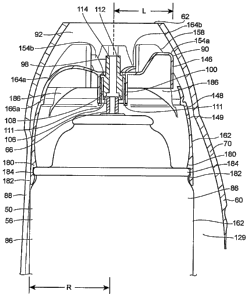
FIGS. 10-14 illustrate a further embodiment of valve actuating apparatus 146
wherein structures common to previous embodiments are assigned like reference
numerals. FIG. 11 shows the valve actuating apparatus 146 incoiporated in an
actuator
cap 148 that may be fitted onto the container 50. A main wall 149 of the cap
148
decreases in cross 'sectional size along an axial dimension defined between
first and
second ends 150, 152, tapering from the end 150 to the end 152. Referring also
to FIG.
10, a first arm 154a is integral with the wall 100 surrounding the nozzle 98
and has a
length L as measured between the surface 90 and the center of the valve stem
66. The
center of the valve stem 66 is substantially coincident with the center of the
actuator cap
148. FIG. 10 shows that a portion of the inner circumferential wall 106 of the
nozzle 98
may be tapered to facilitate insertion of the valve stem 66 therein. The arm
154a extends
in a direction transverse to the axial dimension such that the surface 90 is
disposed beyond
a portion 158 of the main wall 149. When the cap 148 is fitted to the
container 50, one or
both of the cap 148 and the container 50 define an outermost periphery 162,
and the arm
154a preferably (although not necessarily) does not extend beyond the
outermost
periphery 162. A flexible strap member 164a extends from the circumferential
wall 100 in
a direction opposite the.arm-154a. Referring to FIG: 11, additional arms 154b,
154c may -
be provided, and the arms 154a-154c are spaced apart by 120 . Strap members
164b, 164c
CA 02562422 2006-10-10
WO 2005/097621 PCT/US2005/009772
-9-
extend in diametrically opposite directions to the arms 154b, 154c. The arms
154a-154c
are cantilevered from the circumferential wall 100, and the arms 154 and the
straps 164
form a monolithic structure attached to the main wall 149 only at areas 166a-
166c of the
main wall 149. The straps 164 and the arms 154 are disposed in recesses
defined between
upright portions 167-172 of the cap 148. The actuator cap 148 provides a
useful centering
function in that exterior surfaces 173a-173f of the upright portions 167-172,
respectively,
maintain the point of discharge 112 of the actuator cap 148, best seen in
FIGS. 10 and 11,
in a centrally located position relative to the discharge opening 62, thereby
minimizing the
potential for product impingement against the surface 92 of the wall 61.
Referring to
L0 FIGS. 13 and 14, a cover 175 may be placed over the cap 148 to prevent
inadvertent
actuation during shipment.
FIG. 14 shows that the actuator cap 148 may include a circumferential inwardly-
tapered flange 180 and a plurality of spaced apart inwardly-directed beads
182. As shown
in FIG. 10, the flange 180 and the beads 182 are snap fitted over a rim 184 of
the container
50 such that the rim 184 is captured between the flange 180 and the beads 182
so that the
actuator cap 148 is captured on the container 50.
FIGS. 12 and 14 show arcuate gussets 186 that provide rigidity to the wall
portions
167-172. FIG. 14 shows ribs 188 that may be provided within the
circumferential wall
100 to engage the exterior surface of the valve stem 66 or of the nozzle 98
fitted to the
valve stem 68. The ribs 188 aid in centering the nozzle 98 and also provide
slightly
flexible contact points between the circumferential wall 100 and the nozzle
98,
accommodating minor variances in the size of either part.
FIGS. 15-19 show an alternative actuator cap 200 having an arm in the form of
a
lever member 204. The lever member 204 extends in a direction transverse to
the axial
dimension and terminates at the outer peripheral surface 90, which is disposed
beyond a
portion 208 of the wall 149 of the cap 200. However, the lever member 204
preferably
does not extend transversely beyond an outer diameter of the first end 150.
Referring to
FIGS. 16 and 19, the lever member 204 is pivotable about a hinge portion 212
connected
to the wall 149. The surface 90 of the lever member 204 traverses an arcuate
path as the
-lever--member 204 is-pivoted downwardly. At a point-represented by a phantom
line 210,
the surface 90 does not extend beyond any portion of the wall 149 such that
the lever
CA 02562422 2006-10-10
WO 2005/097621 PCT/US2005/009772
-10-
member 204 cannot move downwardly more than a particular distance owing to the
fact
that the lever member 204 is shielded by the wall 149. Therefore, when the cap
200 is
disposed on the container 50 it is not possible to deflect the lever member
204, and hence
the valve stem 66, more than the particular distance.
FIGS. 20-22 show another actuator cap 220 having a plurality of arms 224
radiating from the circumferential wall 100, and thus a plurality of the
surfaces 90 are
provided at circumferentially spaced positions. Providing a plurality of the
surfaces 90 at
spaced apart positions, such as 180 , ensures substantially axial
reciprocating movement
of the valve stem 66, rather than tilting movement, potentially minimizing
product
discharge against the wall 61 of the housing 60. Each of the plurality of the
arms 224 may
be connected to the cap 220 by any suitable means such as flexible tethers or
straps 226
that flex outwardly or inwardly when the arms 224 are pushed toward the
container 50.
FIG. 23 illustrates an actuator cap 230 having an arm 232 that extends
laterally
beyond the exterior surface 86 of the container 50 and also laterally beyond
the maximum
radial dimension of the actuator cap 230. It should be evident from FIG. 23
that the valve
actuating apparatus 52 could extend laterally beyond either or both of the
maximum radial
dimension of the actuator cap 230 and the container 50.
The foregoing embodiments may provide one or more of the following advantages.
First, because the valve actuating apparatus 52 has a sufficiently large value
of L,
ZO preferably having any suitable value greater than about one half the
container radius R, the
valve actuating apparatus 52 is usable with the housing 60 to dispense product
therefrom
even though the discharge opening 62 is large. (As noted above, the cross
sectional size of
the discharge opening 62 is greater than the container radius R.) Containers
lacking an
actuating apparatus of the length L as defined previously are not usable with
the housing
2_5 60. This may be useful because containers lacking the required valve
actuating apparatus
52 may not be designed for use with the housing 60 or the housing 60 may not
be
marketed for use with a particular container of product that lacks the valve
actuating
apparatus 52. For example, the housing 60 may be marketed for use with a
container of a
specific type of insecticide sold with the valve actuating apparatus 52. In
addition, a
30 -longer-L value-may be advantageous from -a manufacturing tolerance
standpoint-because it - --
may be easier to control tolerances of L for a large valve actuating apparatus
rather than a
CA 02562422 2006-10-10
WO 2005/097621 PCT/US2005/009772
-11-
small valve actuating apparatus having a smaller tolerance range. A further
advantage of
the large discharge opening 62 and large value of L is that contact near the
outlet 112 is
avoided. Because the wall 61 contacts the outer peripheral surface 90 at the
distance L
from the orifice of the valve stem 66, the potential for product obstruction
or impingement
is minimized. This feature could be especially advantageous for some products
that fan
out while discharging from the container 50 as the product gets farther away
from the
container 50. The large cross sectional size of the wall 61 would accommodate
such
fanning out while minimizing product impingement or deposition thereupon. A
further
advantage of the large discharge opening 62 is that the surface 92 of the wall
61 may be
easily manually accessed for cleaning. Regarding the embodiment of FIGS. 15-
19,
because the length L is selected relatively long, the lever arm 204 has
significant
mechanical advantage at least according to this embodiment. A further optional
advantage
of the large value of L is that the valve actuating apparatus 52 may be easily
displaced by
hand if a user removes the container 50 from the housing 60 and manually
displaces same.
In this regard, the relative large value of the length L allows the user to
maintain her hands
away from product discharging from the container 50 in the event of such
manual
actuation. Also, the large size of the discharge opening 62 may require less
material to
construct the housing 60, and hence less cost.
A dispensing method may include providing the container 50 as shown in FIGS. 4
and 5 and placing same within the interior space defined by the housing 60.
The container
50 is advanced axially toward the discharge opening 62 such that the
peripheral 'surface 90
pushes against the wall 61, thereby actuating the valve apparatus 52 and
dispensing
product from the housing 60.
In addition, one might also practice methods of providing actuating apparatus
to an
end user. In a first method of providing apparatus to an end user, one may
provide the
container 50 and the valve actuating apparatus 52 and then deliver these to an
end user
through any suitable form of delivery or distribution, whether by distribution
through
stores, promotional events, United States mail, common carrier, or other
suitable sales or
distribution channels. It should be noted that the container 50 and the valve
actuating
30- -- apparatus 52 need not -be sold to- a consumer-in--every instance, but
either- or both of these -
items could instead be given away without charge for promotional purposes. It
should
CA 02562422 2006-10-10
WO 2005/097621 PCT/US2005/009772
-12-
also be noted that while the container 50 and valve actuating apparatus 52 are
preferably
distributed at the same time, these items could be distributed at different
times so long as
at some point in time the end user is in possession of both the container 50
and the valve
actuating apparatus 52 for use with the housing 60. A further optional step
includes
identifying the container 50 as usable within the housing 60. This
identification may take
many forms sufficient to indicate to the end user that the container 50 and
the valve
actuating apparatus 52 are suitable for placement within the housing 60. For
example, the
container 50 could simply be affirmatively identified as intended or suited
for use in an
existing commercial product that is equipped with the housing 60. The
identification
could include written directions for using the container 50 and the valve
actuating
apparatus 52 and these directions could be sold with the container 50 and/or
the valve
actuating apparatus 52. Alternatively, the identification may be in the form
of one or more
pictorial diagrams that illustrate a housing having a tapered wall or diagrams
of the
container 50 and the valve actuating apparatus 52 in the housing 60 having the
wall 61
and/or the farge discharge opening 62.
Industrial Applicability
The foregoing embodiments are useful for dispensing a variety of products such
as
insecticides, cleaning products, air treatment products (e.g., air
fresheners), or other
ZO products.
Numerous modifications to the present invention will be apparent to those
skilled
in the art in view of the foregoing description. Accordingly, this description
is to be
construed as merely exemplary of the inventive concepts taught herein and is
presented for
the purpose of enabling those skilled in the art to make and use the invention
and to teach
the best mode of carrying out same. The exclusive rights to all modifications
which come
within the scope of the appended claims are reserved.