Note: Descriptions are shown in the official language in which they were submitted.
CA 02562810 2014-06-20
CENTRAL VACUUM CLEANER
MULTIPLE VACUUM SOURCE CONTROL
FIELD OF THE INVENTION
The invention relates to central vacuum cleaning systems.
BACKGROUND OF THE INVENTION
Central vacuum cleaning systems were originally quite simple. One placed a
powerful central
vacuum source external to the main living space. The source was connected
through interior walls
to a long flexible hose that terminated in a handle and nozzle. When an
operator desired to use the
system, the operator went to the source and turned it on. The operator then
went inside, picked up
the handle and directed the nozzle to an area to be cleaned.
Although many elements of the basic system remain, many improvements have been
made. Rigid
pipes typically run inside interior walls to numerous wall valves spaced
throughout a building. This
allows an operator to utilize a smaller hose while covering an equivalent
space. This is an advantage
as the hose can be quite bulky and heavy.
Various communication systems have been developed. Some systems sense sound or
pressure in the
pipes to turn the vacuum source on or off, see for example United States
patent no. 5,924,164 issued
20 July 1999 to Edward W. Lindsay under title ACOUSTIC COMMUNICATOR FOR
CENTRAL
VACUUM CLEANERS. Other systems run low voltage wires between the source and
the wall
valve. The source can be turned on and off at a wall valve by a switch that
may be activated by
insertion or removal of the hose. The hose may also contain low voltage wires
to allow the source
to be controlled from a switch in the handle, see for example United States
patent no. 5,343,590
issued 6 September 1994 to Kurtis R. Radabaugh under title LOW VOLTAGE CENTRAL
VACUUM CONTROL HANDLE WITH AN AIR FLOW SENSOR. The switch can be a simple
toggle switch, or a more sophisticated capacitive switch.
- 1 -
CA 02562810 2006-10-06
The low voltage wires running along the pipes can be replaced by conductive
tape or the like on the
pipes, see for example United States patent no. 4.854,887 issued 8 August 1989
to Jean-Claude
Blandin under title PIPE SYSTEM FOR CENTRAL SUCTION CLEANING INSTALLATION.
Separate low voltage conductors in the walls can be avoided altogether by
using mains power wires
to transmit communication signals between the wall valve and the source, see
for example United
States patent no. 5,274,878 issued 4 January 1994 to Kurtis R. Radabaugh, et
al. under title
REMOTE CONTROL SYSTEM FOR CENTRAL VACUUM SYSTEMS. A handheld radio
frequency wireless transmitter can be used by an operator to turn the source
on or off, see for
example US patent no. 3,626,545 issued 14 December 1971 to Perry W. Sparrow
under title
CENTRAL VACUUM CLEANER WITH REMOTE CONTROL.
Line voltage can be brought adjacent the vacuum wall valves and connected to
the handle through
separate conductors, or integrated spiral wound conductors on the hose. Line
voltage can then be
brought from the handle to powered accessories, such as an electrically-
powered beater bar,
connected to the nozzle. Line voltage can be switched on and off to the
powered accessory using
the same switch in the handle that controls the source. Alternatively, the
powered accessory may
have its own power switch.
A control module mounted to the central vacuum unit is typically used to
control the vacuum source.
In an effort to increase suction, it is known to utilize two motors in a
central vacuum unit under the
control of the control module.
Improvements to, or additional or alternative features for, central vacuum
cleaning systems are
desirable.
SUMMARY OF THE INVENTION
In a first aspect, the invention provides a central vacuum cleaning system
including a plurality of
vacuum sources, a control circuit, and a plurality of switches. Each switch is
associated with a
respective one of the vacuum sources. The control circuit is adapted to
control the switches. Each
switch is adapted to apply power to its associated vacuum source in accordance
with control from
the control circuit.
The control circuit may be a plurality of control circuits with each control
circuit associated with a
- 2 -
CA 02562810 2006-10-06
respective one of the vacuum sources and one of the control circuits adapted
to act as a master
control circuit while the remaining control circuits are adapted to act as
slave control circuits such
that each slave control circuit is adapted to control its associated switch
under control of the master
control circuit.
Each switch may be a continuously variable control switch that is able to
apply a continuously
variable amount of power. Each switch may include a triac. Each switch may be
mounted on a
distinct heat sink. Each switch and the vacuum source with which it is
associated may be mounted
in a separate central vacuum unit.
The master control circuit may be adapted to control the slave control
circuits in accordance with a
master soft start function to limit instantaneous total inrush current of the
vacuum sources. The
master control circuit and slave control circuits may be adapted for master
slave control using
wireless RF communication.
In a second aspect the invention provides a method of operating multiple
vacuum sources in a
central vacuum cleaning system. The method includes associating a plurality of
switches with the
vacuum sources. Each switch is associated with a respective one of the vacuum
sources. The
method also includes controlling the switches using a control circuit to apply
power to the vacuum
sources.
Controlling the switches using a control circuit may include controlling the
switches using a
plurality of control circuits with the method further including associating
each control circuit with a
respective one of the switches. Using a plurality of control switches may
include controlling the
switches to limit instantaneous total inrush current to the vacuum sources.
Other aspects of the invention will be evident from the principles contained
in the description and
drawings herein.
BRIEF DESCRIPTION OF THE DRAWINGS
For a better understanding of the present invention and to show more clearly
how it may be carried
into effect, reference will now be made, by way of example, to the
accompanying drawings that
show the preferred embodiment of the present invention and in which:
FIG. 1 is a control schematic of a preferred embodiment of a central vacuum
cleaning system.
- 3 -
CA 02562810 2006-10-06
FIG. 2 is a perspective view of a preferred embodiment of a control module for
use in the central
vacuum cleaning system of FIG. 1.
FIG. 3 is a control schematic of a preferred embodiment of a central vacuum
cleaning system.
FIG. 4 is a cross-section of a structure incorporating a preferred embodiment
of a central vacuum
cleaning system.
DETAILED DESCRIPTION OF THE PREFERRED EMBODIMENT
Referring to FIG. 1 and 4, a central vacuum cleaning system 1 has multiple
vacuum sources 3. The
multiple vacuum sources 3 are connected through pipes 4a to wall valves 4b. In
use a hose 4c is
plugged into one of the valves 4b. A handle 4d is connected to the hose 4c. A
wand 4e extends
from the handle 4d. Attachments 4f such as a power brush are connected to the
wand 4e. Switches
5 apply power from one or more power sources 7 to the vacuum sources 3. The
application of
power by the switches 5 is controlled by a control circuit 9. The control
circuit 9 ordinarily operates
off low voltage DC while the vacuum source 3 typically operates from AC line
voltage.
Accordingly an AC-DC power supply 10 is provided for the control circuit 9.
Referring to FIG. 2, each switch 5 is mounted on a heat sink 11. Each switch 5
is preferably a
continuously variable switch 5, such as a solid state triac, that applies a
continuously variable
amount of power to the vacuum source 3 under the control of the control
circuit 9. This allows for
such features as variable speed. The control circuit 9 may be made up of
discrete components;
however, preferably the control circuit 9 will be based on a microcontroller
and related circuitry.
The various control functions of the microcontroller are implemented through
instructions stored in
a memory of the microcontroller or a separate memory.
Using multiple vacuum sources can increase the suction of a central vacuum
cleaning system.
Using multiple switches 5 can avoid heat and power limitations of a single
switch implementation
for multiple vacuum sources. Use of a single control circuit 9 and multiple
switches 5 can minimize
the components required to implement a multiple vacuum source cleaning system.
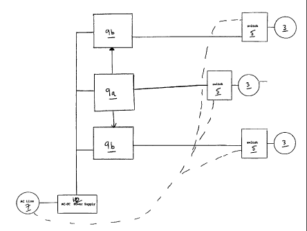
Referring to FIG. 3, each of the switches 5 can be controlled by its own
control circuit 9 with one
control circuit acting as a master control circuit 9a for the other control
circuits 9b. This allows for
- 4 -
CA 02562810 2006-10-06
manufacture of a single control circuit 9 for either master or slave
operation. The designation of
master and slave can be easily implemented in many ways, such as for example,
through respective
DIP switches, not shown, in the control circuit 9.
Referring again to FIG. 2, a switch 5 and a control circuit 9 may be
incorporated in a single control
module 13. The control module 13 also includes heat sink 11. The control
circuit 9 is mounted on a
printed circuit board 15. The switch 5 is mounted on the printed circuit board
15 and the heat sink
11.
Referring to FIG. 4, each switch 5 and the vacuum source 3 it controls may be
in a separate central
vacuum unit 17. As shown in FIG. 4, the switches 5 are part of a control
module 13 from the
configuration of FIG. 2. The switches 5 could be separately implemented in
distinct central vacuum
units 17 and controlled from a single control circuit 9 as shown in FIG. 1.
Use of multiple control
circuits 9 configured in master slave relationships allows each control
circuit 9 to utilize its own
intelligence for functions such as soft start.
Preferably the master control circuit 9a has a master soft start function that
allows for coordinated
start of the vacuum sources 3. As the vacuum sources 3 are drawing power under
the application of
multiple switches, it is possible to apply full power to each vacuum source 3.
If all sources 3 are
started together then the total inrush current can be significant. A master
soft start function in the
control circuit 9 can be implemented to limit instantaneous total inrush
current in different ways.
For example, the switches 5 can be controlled to apply power to the vacuum
sources 3 one after the
other, or to apply less power to each vacuum source 3 while starting multiple
vacuum sources 3. A
combination of these could also be used.
Communication between the control circuits 9a, 9b could be implemented using
wired or wireless
RF communication. Wireless RF communication may be particularly beneficial
where respective
control circuits 9 are in distinct central vacuum units.
The starting or change in speed of additional vacuum sources 3 could be
instigated by a user. For
example a control 21 could be provided on the hose handle 4d for the user to
request more or less
suction. This is communicated to the master control circuit 9a. Preferably
communication from the
handle 4d to the circuit 4a is through wireless RF; however, other wired or
wireless communication
means may be used.
- 5 -
CA 02562810 2014-06-20
It will be understood by those skilled in the art that this description is
made with reference to the
preferred embodiment and that it is possible to make other embodiments
employing the principles of
the invention which fall within its scope as defined by the following
claims.
- 6 -