Note: Descriptions are shown in the official language in which they were submitted.
CA 02562826 2006-10-13
WO 2005/103842 PCT/US2005/012786
-1-
CALIBRATION OF HOLOGRAPHIC DATA STORAGE SYSTEMS USING
HOLOGRAPHIC MEDIA CALIBRATION FEATURES
Description
This application claims priority to U.S. Provisional Patent Application No.
60/563,041
filed 16 April 2004, which is herein incorporated by reference.
Field of the Invention
This invention relates to a system, method and apparatus for calibrating
holographic
data storage systems using calibration features of holographic data storage
media, and relates
particularly to holographic data storage media having calibration features for
optimizing the
operation of holographic data storage systems, and systems, methods, and
apparatus for
holographic data storage utilizing such calibration features. The invention is
useful for
enabling alignment and analysis of holographic media when installed in
different holographic
data storage systems, such that each holographic data storage systems can
optimally operate
with such holographic media for reading or writing holographic data.
Background of the Invention
Holographic data storage systems (HDSS) operate with suitable holographic data
storage media, such as photopolymer material for recording and/or reading of
holographic
gratings or holograms. For example, photopolymer materials designed as
holographic media
are marketed and sold by InPhase Technologies of Longmont, Colorado, and
Aprilis, Inc. of
Maynard, Massachusetts. As with any data storage system, it is critical that
HDSS optical and
mechanical alignments are maintained in order to optimize the performance of
the system.
With a HDSS, there are a number of opto-mechanical subsystems that require
aligmnent. Such
subsystems include, for example, write optics, read optics, reference beam
optics, laser and
beam shaping optics and mounts, and detector mounts. Such an HDSS is shown for
example
in U.S. Patent No. 5,621,549. In page-based HDSS, the opto-mechanics can be
complicated
since imaging is through a two-dimensional spatial light modulator (SLM) array
onto a two-
dimensional detector array with an optical system of reasonably high NA (0.3
to 0.7) in order
achieve high storage capacities. Unlike the optical system for a CD and DVD,
the HDSS
should both mechanically and optically align to holographic media as the media
physically
changes over its usage and environment conditions. Unlike in non-removable
data storage
media, such as magnetic hard disks, positioning errors often occur when media
written by one
HDSS needs to be read by another HDSS. It is difficult to ensure absolute
alignment of optics,
CA 02562826 2006-10-13
WO 2005/103842 PCT/US2005/012786
-2-
mechanics and media from HDSS drive to HDSS drive, it is therefore desirable
to calibrate
each drive before a read or write event.
For certain holographic media it may be difficult to ensure absolute media
conditions
from disk to disk. If holographic media is prone to significant physical and
chemical changes
over time, these changes can affect the quality of pre- and post-recorded
media. Physical
changes can occur for example, in photopolymer recording media which relies on
the formation
of polymer chains within the recording media in order to form holographic
diffraction gratings.
The formation of polymer chains can be initiated by photonic or thermal
energy. In order to
record holographic diffraction gratings that are suitable for data storage, it
is desirable for the
HDSS drive to be able to measure and characterize the amount of pre-recorded
polymerization
that has occurred in a given media. If the HDSS drive can measure the amount
of prerecorded
polymerization that has occurred, it would be desirable to set the optimum
drive conditions in
order to ensure the quality of the recorded holographic gratings. Some of the
HDSS drive
parameters that need to be optimized for a given media include, for example,
exposure energy
dosage, object and reference beam incident angles, and media position relative
to the optical
system.
In addition to measuring the extent of pre-recorded polymerization in
holographic
media, it is also desirable to measure the extent of volume shrinkage in
photopolymer media.
Volume shrincage typically occurs in photopolymer media due to the difference
in volume
between polymer chains created during polymerization and the unpolymerized
monomer
media. A detailed explanation of volume shrinkage in photopolymer HDSS media
can be
found in D. A. Waldman, H.-Y. S. Li, and M. G. Homer, "Volume shrinkage in
slant fringe
gratings of a cationic ring-opening holographic recording material," J. of
Imaging Science ~z
Technol. 41, 497-514 (1997). Volume shrinkage in a photopolymer media results
in a Bragg
mismatch, such that the original reference beam used to a record a given
hologram is no longer
Bragg matched as a reading reference beam for the hologram that is stored
within the
holographic material. Due to shrinkage, it is also desirable to adjust the
planar incident angle
of the reference beam to Bragg match the holographic grating and achieve
maximum
diffraction efficiency during holographic read back. A result of a change in
incident angle of
the reference beam is a spatial shift in the reconstructed data page image on
the detector plane.
Therefore it is desirable for a HDSS to be able to measure the volume
shrinkage in holographic
media and characterize the necessary reference beam angle shift in order to
achieve maximum
diffraction efficiency. Moreover, it is further desirable to characterize and
accommodate the
spatial shift of the reconstructed image on the detector plane.
CA 02562826 2006-10-13
WO 2005/103842 PCT/US2005/012786
-3-
U.S. Patent No. 5,838,650 describes the use of at least one area of a SLM and
of a
matching detector array in a HDSS that are reserved for the monitoring and
controlling of
image quality of the HDSS. Page indicators include information such as page
image indicators,
page identity information and pixel registration keys. Such page indicators
provide image
quality improvement via adjustments to the HDSS that originally stored the
data page
containing such page indicator marks, but not any other HDSS. In this patent,
calibration is
limited to the adjusting a parameter of the system that originally recorded
the page indicators
being monitored. Thus, it would be desirable to have calibration features
recorded at the
factory level, or by another HDSS that is outside of the factory, which can be
different from the
HDSS reading the calibration features, and further to provide calibration of
media and drive
parameters which are not limited to calibration of image quality.
U.S. Patent No. 5,920,536 describes the use of a page indicator marks for
image
aligiunent. A pixel registration key is monitored and if a misalignment
between the image
pixels and the detector pixels is detected, either the detector or the data
page image is moved.
Although this patent describes movement of the detector, the data page image
is not shifted to
correct for misalignment. Further, U.S. Patent No. 5,982,513 describes the
method of tilting
the incident reference beam such that the pixilated image of a data page is
aligned with respect
to the pixels of a detector array. However, neither U.S. Patent No. 5,920,536
nor 5,982,513
provide for alignment utilizing any calibration features on the holographic
media.
U.S. Patent No. 6,625,100 describes the use of an optically detectable pattern
on a
holographic media for the purposes of determining the physical location of a
data storage
location on the holographic media. The pattern is used for tracking data
storage locations on
the media, rather than for calibration of the optical and mechanical alignment
parameters of a
HDSS for the media.
Summary of the Invention
Accordingly, it is a feature of the present invention to provide holographic
data storage
media having calibration features for optimizing the operation of holographic
data storage
systems, and holographic data storage systems operative with holographic media
containing
calibration features for optimal holographic recording, reading, or searching
of information by
any holographic data storage system.
Briefly described, the present invention embodies holographic data storage
media
having at least calibration features having sufficient information for
enabling the optimization
of operation of a HDSS with the media. In a first embodiment, such calibration
features are
holograms holographically recorded into a photosensitive material of the
holographic media,
and as such are recorded via an index of refraction modulation within one or
more materials
CA 02562826 2006-10-13
WO 2005/103842 PCT/US2005/012786
-4-
contained within the holographic media. In a second embodiment, such
calibration features
may represent surface-relief features along one or more external andlor
internal surfaces of the
holographic media. In a third embodiment, such calibration features are
regions of differing
transmission or reflection which store information in changes in amplitude of
a signal provided
when such regions are illuminated by an incident optical beam. In a fourth
embodiment, such
calibration features magnetically store information on the media. In a fifth
embodiment, such
calibration features of a holographic media consist of any combination of
surface-relief,
volume holography, magnetic, and amplitude features of the first, second,
third, and fourth
embodiments, respectively.
In all of the above embodiments, one or more of such calibration features may
contain
information about the properties of the media. Such properties may include but
are not limited
to media thickness, available media capacity, media sensitivity, required
exposure schedule,
media manufacture date, or extent of volume shrinkage. Calibration features
may also contain
information about media format characteristics. Media format characteristics
may include for
example, location of data fields, location and format of table of contents,
location of other
calibration features, or sector information. Calibration features that contain
information about
the media and its formatting are referred to herein as media calibration
features. The
calibration features that are part of a holographic media may also contain
information that
allows a HDSS to optomechanically calibrate its systems such that the
holographic media can
be optimally written and read. Optomechanical calibration alignment may
include the proper
incident angle of a reference beam (for the example of angle and azimuthal
multiplexing),
proper media position, or alignment of a holographically reconstructed image
relative to a
detector array. Such calibration features that serve an HDSS to perform opto-
mechanical
aligmnents are refeired to herein as system calibration features. Other
calibration features are
referred to herein as performance calibration features. Performance
calibration features are
written and read baclc by a HDSS into a holographic media before actual user
data is written.
Through reading back the written performance calibration features, the HDSS is
able to
ascertain the performance characteristics of the media, such as sensitivity
and available
dynamic range. In this mamier, the HDSS can take into account any aging of the
holographic
media that may change the exposure scheduling required for writing multiplexed
holograms as
well as the available capacity of the holographic media.
In all of the above embodiments, such calibration features may be located on
or within
the media at predefined locations. These locations will allow different
holographic systems of
the present invention to locate and retrieve the calibration features. The
calibration features
may also, or instead, be located on or inside the media relative to other
calibration features that
CA 02562826 2006-10-13
WO 2005/103842 PCT/US2005/012786
-5-
may include for example, regions of differing transmission or reflection,
which represent
changes in amplitude of a signal provided when such regions are illuminated by
an incident
optical beam. Such features for locating and retrieving calibration features
may also be
magnetic and readable by a magnetic head read device. In either case, the
calibration features,
optical or magnetic in nature, may contain information about the media for
calibration or
contain information about the location ox properties of other calibration
features allowing for
additional optimization of a holographic system for use with the media.
It is also desirable that the holographic media contain calibration features
that are
recorded at different stages in the media lifetime. For example, the
calibration features may be
written when the holographic media is manufactured, or shortly thereafter, but
before the
holographic media is to be used by the HDSS of a user. This stage of the
holographic media
life is termed the factory level, and calibration features recorded at this
time preferably are
media and system calibration features. For example, the factory-level recorded
system
calibration features serve the purpose of allowing the HDSS of a user to align
its opto-
mechanics relative to some predefined standard set of alignment parameters
used to record the
features during manufacturing. In addition to factory recorded calibration
features, it may be
necessary for the end user to record performance calibration features in
holographic media
before data is recorded in the media. This allows the properly equipped HDSS
to determine the
characteristics of the media, which may include for example, the available
media capacity, the
extent of volume shrinkage, or proper exposure energy dosage for recording.
The present
invention provides for holographic recording media containing calibration
features that are
recorded at the factory level or in another system, for example an end-user
system.
The invention further provides a system, method, and apparatus for reading
information
from the calibration features of holographic data storage media when located
in a HDSS, in
which the HDSS operate responsive to such information for optimizing
parameters of the
HDSS to ensure optimal operation of the HDSS with the media. Thus, holographic
data
storage media written in one HDSS can be read by another HDSS, thereby
allowing for the
interchange of removable holographic media between two or more different
holographic
optical drives.
In the preferred embodiment, the HDSS of the present invention reads and
utilizes
media calibration features that are holographic or diffraction gratings. The
HDSS may use the
primary holographic optical, mechanical and electronic system typically used
for reading,
writing, or searching of data in order to read and utilize the diffractive
calibration features.
Alternatively, the HDSS may contain a system in addition to read, write and
search system,
where the additional system is used for reading diffractive calibration
features.
CA 02562826 2006-10-13
WO 2005/103842 PCT/US2005/012786
-6-
Further, the HDSS may have an optical, mechanical and electronic system,
separate
from the read/write holographic system, for reading non-holographic or grating
calibration
features of the media, such as amplitude varying features. By having a
separate system, and
preferentially one of low complexity and loose tolerances compared to those of
the read/write
system for user data, the HDSS can be programmed to accept a wide variety of
holographic
media. This lower complexity system is designed to read calibration features
of lower
resolution, preferably media calibration features. The separate optical
'system may be replaced
or combined with a magnetic pickup system for reading magnetic calibration
features of the
media. The operation of an HDSS may be for example, one in that the HDSS first
reads the
non-holographic or grating calibration features of the media, such as
amplitude varying features
in order to obtain the location of the system holographic calibration
features.
The HDSS reads the media calibration features to obtain information about the
media,
for example, media properties or media format. Media property information, for
example, may
include one or more of the following: photosensitive layer thickness, media
fabrication date,
media fabrication lot number, media sensitivity and exposure schedules, as
well as the media
manufacturer. Format information, for example, may include one or more of the
following:
track pitch, reference beam orientations for reading and writing, and location
of other
calibration features.
Once the HDSS reads such media information and formatting information from the
media calibration features, it adjusts its opto-mechanics accordingly and
begin to read the
system calibration features, whose locations are either recorded in the media
calibration
features or stored (for example via firmware or software) in the HDSS memory.
The system
calibration features allow the HDSS to align its holographic read head over
one of the
calibration areas or regions on the media and fine-tune optomechanical
alignment,'such as the
focus, lateral alignment, and orientation of the reference beam until the
signal strength (and
hence SNR) from a system calibration feature has been peaked. Such system
calibration
features allow compensation for slight manufacturing differences between
drives as well as for
thermal changes in the drive and/or media.
The invention also provides for an HDSS capable of writing, or writing and
reading, of
holographic performance calibration features on the media to dynamically
provide information
about characteristics of the media, such that HDSS operating parameters may be
adjusted for
optimal writing of holographic data. Such parameters, for example, are laser
power or write
energy dosage.
As stated earlier, calibration features may be written at the factory level.
Imparting the
media and system calibration features at the factory level can be accomplished
by providing
CA 02562826 2006-10-13
WO 2005/103842 PCT/US2005/012786
surface-relief structures and/or volume holographic features. Such surface-
relief calibration
features may be molded directly into a surface of the holographic media during
one or more
stages of the holographic media manufacturing process, while amplitude
calibration features
may be recorded at the factory level such as by silk-screening,
photolithography, or even the
use of pressure sensitive materials and laminates with regions of materials of
different opacity
or reflectivity. Holographic calibrations features recorded in media during
manufacturing can
be recorded by a well-calibrated holographic factory HDSS. The factory HDSS
records
holographic calibration features at calibrated reference beam and object beam
incident angles
and exposure intensities such that an HDSS in the field can read the features.
The holographic
calibration features can be recorded sequentially with an optical pickup that
individually
records each of the plurality of holographic calibration features required in
a holographic
media. The holographic calibration features are recorded and formatted at the
factory level in
such a manner as to enable an HDSS in use in the field to read holographic
media with the
holographic calibration features. For example, the formatting can be such that
an end-user's
HDSS can read at a certain location on the holographic media, and with a
reference beam of a
suitable orientation and beam shape, the calibration data recorded at the
factory level.
The invention also provides for calibration features to be recorded in the
holographic
media using an HDSS drive operated by an end-user. Calibration features of a
known format
are written into the holographic media before user data is written. The
holographic calibration
features are recorded at known locations on the media, such as a disk, and
with known data.
These calibration features recorded by the end-user can be used to measure
media
characteristics. Media characteristics indicated by end-user calibration
features may include,
but are not limited to pre-recorded extent of polymerization, extent of volume
shrinkage,
required energy dosage for writing, and available storage capacity.
An example of a system responsive to signals from such calibration features
aligns the
HDSS to the media over one of more calibration features. The system optimizes
at least one of
the following degrees of freedom of the HDSS: object and reference beam
incident angles,
media position relative to the optical system, detector alignment, or SLM
alignment are
scanned about a local region until the hologram signal to noise is optimized.
Once the signal
from the system calibration feature is optimized, the proper settings of the
HDSS degrees of
freedom are recorded for aligning the media, for example, in a look-up table
in memory of the
HDSS. The degrees of freedom, once stored in a look-up table can be used as a
coordinate list
for the optimal drive settings for a data write event.
Once calibrated, the HDSS system for reading media calibration features, and
aligning
utilizing system calibration features, may further be capable of recording and
then reading back
CA 02562826 2006-10-13
WO 2005/103842 PCT/US2005/012786
_g_
additional calibration features, e.g., performance calibration features, for
the purposes of media
calibration, such as prior to each write event. By recording and reading back
performance
calibration features in the holographic media, the HDSS can determine media
parameters such
as, for example, photosensitivity, useful dynamic range of a holographic
recording media, and
the media volume shrinkage. The conditions for optimum calibration featuxe
read-back will
not always be known a-priori as the media condition, for example, extent of
pre-recorded
thermal or photo polymerization in a photopolymer media may be unknown.
Therefore the
optimal read back parameters of the HDSS are determined through interactions
of read-backs
in which each read-back parameter are optimized independently until each read-
back parameter
is tuned to provide optimum read-back signal to noise ratio with predefined
SNR tolerances.
Once the read-back parameters have been determined and each performance
calibration feature
has been read back and evaluated, the pre-recorded state of the media is
determined, whereby
such optimized parameters are indicative of media photosensitivity and
available dynamic
range. Media photosensitivity and available dynamic range may be used to
determine the
optimum conditions for the recording of holographic data on the media and
storage capacity of
the media.
Brief Description of the Drawings
The foregoing features and advantages of the invention will become more
apparent
from a reading of the following description in connection with the
accompanying drawings, in
which:
FIG. 1 is a schematic block diagram of a system of the present invention in a
holographic data storage system;
FIG. 2 is an optical diagram showing the holographic media and orientation of
the
object and reference beams used for recording of multiplexing co-locational
holographic data
on such media;
FIG. 3 is a plan view of an example of the holographic media of the present
invention having calibration features on media in a disk format, such as may
be used in the
system of FIG. 1;
FIG. 4A is a cross-sectional view of the holographic media of the present
invention
showing an example of a surface relief calibration feature;
FIG. 4B is a cross-sectional view of a portion of the holographic media of the
present
invention showing an example of amplitude calibration features.
CA 02562826 2006-10-13
WO 2005/103842 PCT/US2005/012786
-9-
FIG. 4C is a three-dimensional perspective view of a portion the holographic
media of
the present invention containing holographic calibration features and the read
optical module
for reading such features;
FIG. 4D is a two-dimensional perspective view of an example of a system
calibration
page, such as may be read from a holographic calibration feature of FIG. 4C in
the system of
FIG. 1;
FIG. 5 is a flow chart of the process for reading a sequence of calibration
features from
the holographic media in the system of FIG. 1;
FIG. 6 illustrates the peristrophic alignment of a holographic data page on a
detector
array when the holographically stored data is read with the system of FIG. 1;
and
FIG. 7 is a flow chart of the process for recording and reading performance
calibration
features in the system of FIG. 1.
Detailed Description of the Invention
Referring to FIG. 1, a holographic data storage media 4 having calibration
features is
shown in a holographic data storage system (HDSS) 30. The HDSS has a housing
2~ having
an aperture 2 through which holographic media 4 can be inserted into the HDSS.
In the
example of FIG. 1 the media 4 is in the format of a disk. Aperture 2 may or
may not be light-
tight to illumination such media 4 is sensitive to. Although not shown, the
holographic media
may be contained within a cartridge and is partially or fully removed through
an opening from
the cartridge. For example, such a cartridge and HDSS for operating on media
removable from
the cartridge is shown in International Patent Application No.
PCT/LTS04/33921, and U.S.
Patent Application No. 10/965,570, both filed on October 14, 2004 and having
priority to U.S.
Provisional Patent Application No. 60J510,914, filed October 14, 2003. For
simplicity of
illustration, the cartridge, associated shutters and shutter mechanics for the
cartridge, and the
cartridge loader (or other movable fixture that accepts the inserted
holographic media and
ensures that the holographic media is aligned and mated to the mechanics
required to actuate
the media within the HDSS) are not shown. The media 4 may have a hub, central
opening, or
other attaching mechanism for coupling the media 4 onto a rotary spindle 6
that is attached to a
rotary motor 5. In this manner, the media can be rotated about an axis 9, in a
direction
designated by the arrow 9a. The rotary motor 5 and spindle 6 represent a
rotational stage
which is attached to a linear stage 10 that directs the rotary motor and hence
the holographic
media 4 along the z direction, as indicated by bi-directional arrow 10a,
across the stationary
optics of a write optical module 13 and a read optical module 11. Through the
rotary motion of
the rotary motor 5 and the linear translation of the linear stage 10, a large
annular portion of the
CA 02562826 2006-10-13
WO 2005/103842 PCT/US2005/012786
-10-
holographic media 4 can be accessed. The geometry depicted in FIG. 1 is an
example of
holographic media within an HDSS having fixed write and read modules. However,
optionally
the holographic media 4 may rotate whilst the optical modules for reading and
writing move
across the media, or the holographic media can be stationary and only the
optical modules
move physically or at a minimum, direct the appropriate read and/or write
beams towards the
surface, or the optics can be stationary and the holographic media actuated
via x and y
translation stages rather than the radial and tangential directions depicted
in FIG. 1. The
invention may be embodied in the foregoing HDSS system or other HDSS systems
using
holographic media for read-only or read/write.
The HDSS 30 has transmissive holographic geometry in that the write optical
module
13 and the read optical module 11 are on opposing sides of the holographic
media 4. Each of
the write and read modules are in general composed of a number of optical
elements 14 and 12,
respectively. In the example of the HDSS shown in FIG. 1, light from an
optical source 15 is
split into two beams, reference beam 108 and object beam 109, via a beam
splitter 16. The
optical source 15 may be a laser source operating at a wavelength of light
media 4 is sensitive
to. The object beam 109 is preferably beam shaped by a beam shaping optical
system 18 such
that the intensity falling on a spatial light modulator (SLM) 19 is uniform.
The light 100
reflected from the SLM 19 is relayed to the holographic media 4 via the write
optical module
13. The reference beam 108 passes from beam splitter 16 through a reference
optical system
17 that appropriately shapes the reference beam and allows it to be swept to
different angles of
incidence on the holographic media for the case of angle and/or peristrophic
multiplexing.
Depicted in FIG. 1 is an example of reference beam 108 steered to different
positions 101 and
102 that may be incident upon the holographic media 4 in the case of such
multiplexing. The
reference optical system 17 may further permit other forms of multiplexing,
such as speckle
and shift multiplexing. Reference optical system 17 includes a beam steering
mechanism to
direct the beam at positions along one or more angular dimensions in
accordance with the
multiplexing used by the system. Such beam steering mechanism rnay have one or
more
movable mirrors which direct the reference beam incident thereto towards the
media 4. A
moveable mirror represent one example of a beam steering device, other beam
steering devices
may be used, such as movable optical elements, such as lenses or prisims, or
optical
modulators. A detailed view of the geometry of the reference beam in relation
to the object
beam is shown in FIG. 2 and will be described in detail later.
For reading of data from the holographic media 4, the object beam 109 is
ideally
prevented from illuminating the holographic media. Although not depicted in
FIG. 1, the
blocking of the object beam can be accomplished by an opto-mechanical system
in the path of
CA 02562826 2006-10-13
WO 2005/103842 PCT/US2005/012786
-11-
the object beam after, or in conjunction with, beam splitter 16. Examples of
such opto-
mechanical system may represent mechanical shutters, EO or AO shutters or
deflectors, or the
use of polarization rotation devices in conjunction with beam splitter 16
which may be a
polarization beam splitter. When reading the data stored in the holographic
media 4, the
reference beam 108 illuminates the holographic surface of media 4 with a
series of reference
beam orientations and wavefronts that match the orientations of the reference
beams used
during the writing process. When a given reference beam that matches a
reference beam used
in the recording process illuminates the media, the stored hologram can be
read and the
diffracted light 107 from this hologram is captured by the read module 11 and
imaged onto a
detector 103, such as a two-dimensional charge-coupled device (CCD) or a
complementary
metal-oxide-silicon (CMOS) array. In addition to read or write operations, the
holographic
optical system may also provide searching operations to locate holographic
recorded data on
the media. The search process is similar to a read however the media is
scanned with a
reference beam having the data being searched for until, a hologram having
such data is read.
During both read and write cycles of the HDSS, a servo system 7 is used to
track the
media. The servo system 7 can be used to track the position of the holographic
media 4 as well
as to obtain such information as of the holographic media surface. In one
example, the servo
system is optical and has an optical source, preferably of a spectral
bandwidth that does not
include wavelengths the holographic media is sensitive to, and reflects an
optical beam 8 off of
a surface of media 4 to obtain address information from reflective marks
(encoding radial and
angular positions of the disk media) onto a detector of the servo system.
Although drawn as a
reflective system, the optical servo system is not limited to reflection and
can operate in
transmission or a combination of reflection and transmission. An example of a
reflection
optical servo system 7 is the use of a CD or DVD pick-up head. By having pits
and grooves
similar in size as those found in CD or DVD disks, one can encode such pits
and grooves with
address information and use the same optical pickup head as that used in CD or
DVD drives
with electronics (and/or software) that interpret the data read.
A separate reader system 104 may be incorporated into the HDSS to read some of
the
calibration features on media 4. Such reading system is preferable when the
calibration
features being read are of lower resolution than the system calibration
features on the media
disk and it is preferable that such lower-resolution calibration features
contain information
regarding media and format (e.g., the media calibration features). Media
information should
preferably include information, such as thickness of the photosensitive layer,
manufacture date,
sensitivity, and exposure dose schedules. Format information for example may
contain such
information as location of system calibration features on media 4, in terms of
disk radial and
CA 02562826 2006-10-13
WO 2005/103842 PCT/US2005/012786
-12-
annular position as tracked by servo system 7, and the reference beam settings
required to read
such system calibration features. In one example, the reader system 104
contains an optical
source that probes the holographic media 4 with an optical beam 105 to read
the calibration
features on the holographic media. In another embodiment, the reader system
104 contains a
magnetic head that reads magnetically coded calibration features on the
holographic media.
The opto-mechanical systems in an HDSS require dynamic control and are
connected
via cables (e.g., electrical or optical), to one or more controllers 106. The
controllers 106
within the HDSS can perform a multitude of tasks including, but not limited
to, the control and
timing of the data displayed by the SLM 19, the modulation and power levels of
the optical
source 15, the decoding of data received from the detector 103, the servo 7
controls for tracking
the holographic media 4, the control and timing of the reference beam 10~
wavefront and
orientation for the multiplexing configuration of the HDSS (e.g., via motors
coupled to the
movable mirrors or other beam steering devices) used), and the control of the
reader system
104 reading calibration features on the holographic media. The controllers 106
can also supply
any electrical power needed by these various opto-mechanical systems via the
connections
illustrated by 110. The HDSS internal controllers) 106 may represent one or
more
programmed microprocessor-based devices, which are connected to an external
controller 112
via a coimection 111. This external controller could be a variety of
controllers that include, but
are not limited to, a personal computer, an enterprise library data storage
system, or a computer
20' server.
FIG. 2 shows the exposure geometry of the reference and object beams along a
portion
of the holographic media surface 20 of media 4. Typically, the cone of the
object beam,
described by the cross-section 21 and cone boundary rays 22 is propagating
along a Garner
plane wave 24 that makes an angle Os with respect to the local surface normal
23 of the
holographic media 4. The reference beam is propagating on a carrier plane wave
26 that makes
an angle 0R with respect to the local surface normal and whose projection 25
in the x y plane
(plane defining the orientation of the local surface of the holographic media)
is at an angle ~R
with respect to the y axis. The reference beam itself can be any form of
coherent beam, such as
a plane wave, a converging beam, or a diverging beam, provided that it is
propagating along a
30 Garner plane wave defined by the angles 0R and ~R. With this definition of
the angle ~, the
object beam's projection into the x y plane, makes an angle of ~s = 1
~0° with respect to the y
axis. The reference beam need not be a plane wave but could be a diverging or
converging
reference beam such as one would use for shift-multiplexing of holograms, such
as described,
for example, in G. Barbastathis, M. Levine, and D. Psaltis, "Shift
multiplexing with spherical
CA 02562826 2006-10-13
WO 2005/103842 PCT/US2005/012786
-13-
reference waves," Appl. Opt. 35 (14) 2403-2417 (1996). For angle multiplexing,
the angle 0 of
either or both of the object beams and reference beam changes between
exposures by a value
larger than the Bragg selectivity of the previous hologram stored in the
holographic media.
Angle multiplexing is described, for example, in H. S. Li and D. Psaltis,
"'Three-dimensional
holographic disks," Appl. Opt. 33 (17), 3764-3774 (1994). Since 0 is defined
with respect to
the local surface normal of the holographic surface, tipping and tilting the
holographic media
can also be accomplished for the purposes of angle multiplexing. For the case
of peristrophic
or azimuthal multiplexing, see for example U.S. Patent No. 5,483,365, in which
the orientation
of ~ is changed by some combination of the media, the reference beam, or the
object beam
rotating about the z-axis.
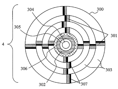
Refernng to FIG. 3, an example of a holographic media 4 with calibration
features is
shown that may be used in HDSS 30. In the top-down view of a holographic media
4, the
media is in the form of a disk having an outer diameter 300 and an inner
diameter 304. Within
the inner diameter 304 may be a hole providing a hub upon which the media can
be inserted
onto the spindle 6 of rotary motor 5. The user data is written in a number of
sectors 303 about
the disk. Each sector, as illustrated, represents an angular wedge portion of
an annular region
of the holographic media. The regions 301 of the holographic media that are
shaded with
slanted hash marks denote the plurality of system calibration features
distributed about the
holographic media. The regions 307 of the holographic media that are blackened
denote the
plurality of regions available for performance calibration features to be
recorded in the
holographic media. As will be detailed later, in particular with reference to
FIG. 7, the
performance calibration features are recorded by the user HDSS and are used to
determine
current media parameters, such as the photosensitivity and data capacity that
is available before
the user HDSS commences a recording session of user data. In this example,
there is one
region of system calibration features and one region of performance
calibration features for
each sector of user data. The region 302 contains media calibration features
and is located
towards the center of the disk, while region 305 is the center annular of the
disk which typically
would not be used for calibration features or data due to possible conflict
with the physical
layout of the rotary motor. Media calibration features providing media and
formatting
information, respectively, are integrated into the holographic media such as
at the factory level,
while the system calibration features could be recorded by a factory HDSS or
user level HDSS.
The annular region 306 marked by the horizontal dashed lines denotes a table
of content (TOC)
sector. In the TOC sector is the information required by the HDSS to determine
data stored on
the holographic media. Such TOC information may include, for example, physical
sectors or
CA 02562826 2006-10-13
WO 2005/103842 PCT/US2005/012786
-14-
memory locations, i.e., physical space (e.g., disk radial and disk angular
position) with the
reference beam settings required to address the stored multiplexed holograms
on the media
disk 4 where user data has been recorded, file names and types and directory
structures for the
user data recorded, and memory locations available for storing new user data.
The TOC sector
is preferentially a region of the holographic media that can be recorded and
read multiple times,
thereby allowing the holographic media to have a plurality of read and write
sessions.
Alternatively, the TOC sector may be a region containing phase change media,
similar to that
incorporated into recordable CDs or DVDs. Such phase change media would allow
a properly
equipped HDSS containing a read and write head similar to that of a CD or DVD
player to
record TOC information to be read by the same or another comparably equipped
HDSS.
Media 4 may be composed of a top substrate and a bottom substrate which
sandwich
photosensitive material suitable for holographic recording in the volume of
such material. The
substrates may be of glass or plastic material. All sides of the media may
also be of such
substrate material, thereby encasing such photosensitive material therein. For
example, such
holographic data storage media is sold by Aprilis, Inc. of Maynard MA, and may
be in different
formats, such as a disk described herein, a card, or other shapes.
There are at least four types of calibration features which may be
incorporated on
holographic media 4, that may include surface-relief grating features,
amplitude features,
magnetic features, and holographic recorded features. Surface-relief grating
features or
holographic features may be used for aligning the angles of the reference beam
to the media.
Amplitude and magnetic features preferentially provide encoding of media and
format
information. Holographic features or surface relief gratings may also be used
for alignment of
read data page upon the detector. Preferably, the system calibration features
of a holographic
media consist of holographic features, however other combinations of surface-
relief, volume
holography, magnetic, and/or amplitude features may be used. Each type of
calibration feature
is described below.
FIG. 4A depicts a cross-section of a holographic media 4 that contains a
calibration
feature that incorporates a surface-relief grating. Such a grating calibration
feature can be used
to calibrate the 0 and ~ angle orientations of the reference beam in a HDSS
that incorporates
angle and or peristrophic methods for the co-locationally multiplexing of
multiple holograms.
In the example depicted in FIG. 4A, a holographic media 4 is composed of a top
substrate 400
and a bottom substrate 401 that are sandwiching a layer of photosensitive
material 402. On the
top surface 403 of the top substrate, a series of grating grooves 404 with
grating period A are
fabricated and oriented such that the grating vector K lies along the y-axis
(e.g., K = 2~ l Ay ).
CA 02562826 2006-10-13
WO 2005/103842 PCT/US2005/012786
-15-
Over the top substrate 400 is a coating 405 that protects the grooves from
scratches. An
example of such a holographic media construction is Type A rriaterial sold by
Aprilis, Inc.,
Maynard, MA. The photosensitive layer and the bottom and top substrate
materials may, for
example, be of polycarbonate material, with an index of refraction of 1.58.
The coating layer
405 may, for example be another organic material with an index of refraction
of 1.46, for
example, thereby allowing sufficient index of refraction difference between
the coating layer
and the polycarbonate layer for diffraction to occur and be detectable.
Optionally, the grating
grooves are metal-coated (e.g., Al) in order to enhance the power in the
reflected diffracted
light. Preferentially the grating is designed to operate in the Littrow
configuration, and as such
will take light of a specific angle of incidence and reflect it directly back
at the source. As
shown in FIG. 4A, light 406 that is incident at an angle 01 relative to the
surface normal 407 of
the holographic media 4 has a reflected diffracted order 408 that counter-
propagates relative to
the incident beam 406. The grating features may provide for a second incident
beam 409
propagating at an angle of incidence of 02, to also reflect a diffracted order
410 that counter
propagates relative to the second incident beam 409. The Littrow condition can
be expressed
as
sin0. _ ~n~' (1)
2yaiA
where 01 is the angle of incidence of the incident light relative to the
surface normal of the
holographic media, m is the diffraction order, ~, is the free-space wavelength
of the incident
light, n~ is the index of refraction of the medium outside of the holographic
media (typically air,
so ni = 1), and A is the grating period of the grating grooves of the
calibration features. A
plurality of gratings can be provided each to be used as a separate
calibration feature for a
different angle of incidence requiring calibration, or a single grating can be
provided that
operates at multiple angles of incidence. As an example, consider the case of
~, = 405 nm,
A = 1900 nm, and nt = 1. In this case, the angles 81 and 02 that would satisfy
the Littrow
condition would be 39.75° and 58.50° for na = 3 and rn = 4,
respectively. Note that a grating
with a grating vector K along the y-axis could calibrate more than one 0
angle, but could at
most calibrate the ~ = 0° and 180° angles (i.e., incident light
whose propagation vector
projected onto the x y plane has a component in the y or - y directions and no
x-axis
component). For calibratingp number of phi angles (assuming that none of these
angles are
related to each other by a 180° rotation in phi), one would require p
gratings with grating
vectoxs Kp such that the direction corresponds with the cep direction of the
incident light. In a
simplified example, a crossed grating can be provided, wherein the two grating
vectors are
CA 02562826 2006-10-13
WO 2005/103842 PCT/US2005/012786
-16-
oriented at 90° relative to each (for example one in the y direction
and one in the x direction).
For example, in one direction the grating period may be 1900 nm as described
earlier in this
paragraph, while in the orthogonal direction, the grating period could be 2000
nm such that a
reference beam oriented at 37.41 ° and 54.10° can be calibrated.
The two gratings need not be
oriented at 90° relative to each, but can be set at an arbitrary angle
relative to each other, and
more than two orientations of gratings (all of which may or may not have
different grating
periods) can be fabricated. For example, the fabrication of such gratings is
described in M. C.
Hutley, "Coherent photofabrication," Opt. Engin., 15, 190-196 (1976), wherein
crossed
gratings are fabricated holographically in photoresist. These photoresist
structures can be
transferred to another medium via an etching or replication process, such as
those described in
Micro-Optics: Elements, Systems, and Applications, ed. by H. P. Herzig (Taylor
& Francis,
Inc. Bristol, PA, 1997).
The surface-relief calibration features may be fabricated in one or more
external and/or
internal surfaces of the holographic media. In the case of surface-relief
calibration features that
reside along an internal surface of the holographic media, a sufficient index
of refraction
difference in required at the interface of the internal surface such that the
surface-relief features
can be detected via transmission, reflection, and/or diffraction changes in an
incident optical
beam. In a preferred embodiment of these surface-relief calibration features,
the features are
replicated into a surface of the holographic media. For example, fox a
holographic media
composed of a photosensitive media that is sandwiched by two plastic
substrates (for example,
polycarbonate substrates), the calibration features can be molded directly
into the surface of the
plastic substrate during the same molding process used to fabricate the
substrates. The surface-
relief calibration features may be directly fabricated, or preferably a master
is fabricated that is
used to mold the calibration features. Such fabrication may be by
photolithography, e-beam
lithography, laser writing, wet aqueous etching, dry etching, and
electroforming processes. The
aforementioned manufacturing processes for the purposes of creating surface-
relief features are
to be considered as examples; other methods for producing such features may
also be used.
FIG. 4B shows a cross-section of a holographic media 4, similar to FIG. 4A,
except that
the calibration features have amplitude features. The reader system 104 used
to read the
amplitude features has an optical source that projects an incident optical
beam 422 towards the
holographic media 4 at an angle that is preferentially normal to the surface,
but non-normal
incident light may be used. The incident optical beam 422 reflects off of the
reflective marks
421 that have been patterned on the top surface 403 of the top substrate 400
of the holographic
media. The change in length in the y-direction of the amplitude features
compared to the clear
featuxes 420 can be detected by the timing of the reflection signal incident
upon a detector
CA 02562826 2006-10-13
WO 2005/103842 PCT/US2005/012786
-17-
integrated into the optical system 104, whilst the holographic media 4 is
moving in a direction
having at least a motion component in the y-direction. The change in the
length in the y-
direction of the amplitude features as well as their relative spacing can be
used to code
information required as part of the media calibration features, such as may be
located at
features 302 in media 4, as described earlier in connection with FIG. 3. An
encoding scheme
may be provided for the serial data provided from detector of reader system
104 to controller
106. For example, run-length-limited (RLL) encoding may be used (e.g., such as
those used in
CD and DVDs), or bar-code type encoding similar to that used with UPC labels,
or other data
encoding schemes. The reader system 104 has a light source 104a and optics
104b which
shape and/or focus the beam from the source onto the media 4, and light
returned from the
media may be shaped and/or focused by the same, or different optics, onto the
detector 104d
contained within reader system 104. A beam splitter 104c in the reader system
104 pass the
beam from the source 104a to optics 104b, while directing return light
received to detector
104d. Amplitude calibration features can be manufactured through a variety of
techniques,
such as silk-screening, photolithography, or through the use of pressure
sensitive materials and
laminates that have regions of different opacity.
As an example, the reader system 104 can use an optical beam from a 655 nm
semiconductor source 104a that is focused with a slow (NA = 0.10) objective
lens 104b onto
the media surface containing the reflective marks 421. The focused spot size
is approximately
8 Eun in diameter and through Gaussian beam propagation has about X100 ~,m of
defocus error
before the spot increases past 13 Vim. The reflective marks can have a code
such that the
minimum length of a clear area 420 or reflective area 421 can be 15 Vim. When
illuminated, the
reflective marks provide return reflected light representative of a code
detectable by an optical
detector 104d of system 104. By using such a slow optical system for reading
the amplitude
calibration features, loose opto-mechanical tolerances that ensure the
holographic media is able
to be immediately read upon being inserted into the HDSS.
Magnetic calibration features can magnetically store information in an encoded
format
on holographic media 4. However, whereas amplitude-varying features can be
formed in the
media material, magnetically recordable material is applied to the media
surface(s), e.g., on the
surface of one or more of the substrates sandwiching the photosensitive
material of the media
or on the coating applied thereto. Magnetic features may be similar to a
magnetic strip of an
identification badge or credit card, such that the reader system 104 has a
magnetic pickup
system having a magnetic read head. The magnetic strip is encoded with the
media and
formatting information similar in the manner in which a credit card or
identification badge
CA 02562826 2006-10-13
WO 2005/103842 PCT/US2005/012786
-18-
magnetic strip is encoded. The magnetic pickup system is disposed in the HDSS
such that
when media 4 is inserted in the HDSS the magnetic pickup system reads the
magnetic features
from magnetically encoded regions) and provides electrical signals to a
controller 106 of the
HDSS representing the encoded data which may then be decoded by the
controller. Attaching
means of such strip to a surface of one of the media substrates may be similar
to that used in a
credit card, or may be a magnetic strip attached by adhesive material.
FIG. 4C shows an example of calibration features that are holographic. In this
example,
the HDSS is multiplexing co-locational holograms using plane-wave angle and
azirnuthal
multiplexing and the optic axis of the read optical module 11 coincides with
the surface
normal, defined as the z-axis, of the holographic media 4. A reference beam
101 is incident on
a calibration feature 432 at an angle of 6R (as measured with respect to the
surface normal z)
and ~R (the angle the x y plane projection 430 of the reference beam's
propagation vector
makes with the y axis). The diffracted light 107 from the calibration feature
is imaged by the
optical elements 12 of the read optical module 11 and the resulting image 431
referred to as the
calibration or alignment page, which is composed of a series of light and dark
pixels, is
projected onto detector array 103. In this example, the holographic
calibration features have
been recorded with holographic data with an HDSS similar to that illustrated
in FIG. 1, with
the calibration features preferentially recorded at the factory-level, if the
holographic
calibration features are system calibration features. These holographic
calibration features in
general store a plurality of holograms, each designed to be read by a
reference beam with a
specific 0R and ~R orientation, so that reference beams of multiple
orientations can be used to
calibrate the opto-mechanical alignment of the HDSS reading the calibration
features. In this
manner, these calibration features are system calibration features. One or
more of such
holographic system calibration features may provide data pages when read
wherein said data
pages have pixels of known two-dimensional location (x,y) or marks which are
aligned with
pixel positions of the detector array of the HDSS and/or may have holographic
data describing
the original recording parameters of the holographic calibration feature in
the media.
The holographically recorded calibration features are recorded into the
holographic
media and as such are recorded via an index of refraction modulation within
one or more
materials contained within the holographic media. The location of the material
of media 4 in
which the holographic calibration features are recorded may or may not be the
same location as
is used to record and/or playback data, termed user data, that the holographic
media is intended
r
to store for the end user. The holographic calibration features axe detected
through the use of
an incident optical beam that will diffract in reflection and/or transmission
upon encountering
CA 02562826 2006-10-13
WO 2005/103842 PCT/US2005/012786
-19-
the holographic features. The incident optical beam rnay or may not be the
same optical beam
or be from the optical source as that used for recording andlor reading user
data. In a preferred
embodiment, the holographic calibration features can be read by the same
optical system used
to record and/or read user data, and in this method, direct feedback with
regards to the opto-
mechanical alignment settings for the optical system can be obtained.
An example of a calibration page 431 recorded in a system calibration feature
is shown
in FIG. 4D. In this example, the calibration page 431 has four locations 450
wherein alignment
marks are placed. These alignment marks are composed of a set of pixels 451,
whose
composition is known (through the reading of media calibration features or
through data stored
in the firmware memory or software of the HDSS) by the HDSS reading the
calibration page,
wherein some pixels have no light 452 and some have light 453. In this example
a simple
cross-hair is used as the alignment mark, but a plurality of marks and
different mark formats
may be used. Looking at a close-up of a smaller region of pixels 454 with
respect to the
detector 103 pixels, the calibration page pixels, e.g., 456, are not properly
registered relative to
the detector pixels, e.g., 455, and in general have misalignments in the x and
y directions of ~1x
and tly, respectively. The alignment marks of the calibration page can be used
to align the
opto-mechanics of the HDSS. The calibration page, preferentially, has a region
of the page 457
that is referred to as a calibration page header. The calibration page header
is dedicated to
storing data in a set of pixels 458 that indicates properties of the
calibration hologram.
Properties of the calibration hologram that are recorded in the header may
include, for example,
the address of the hologram within a series of calibration holograms, the
incident angle of the
recording reference beam, the expected amount of media volume shrinkage, or
energy dosage
used for recording the calibration hologram. For the example of a HDSS that is
designed for
planar angle and azimuthal multiplexing, the term "address" of a hologram on
media 4 has four
components, a physical position at a radial degree and angular degree on the
disk, as
determinable from tracking information from servo system 7, and the angles 8
and c~. The
physical position may be in accordance with mechanical position encoders of
rotary motor 5
and linear translation stage 10, and/or software in controller 106 for sending
signals to such
motor and stage. Angles 0 and ~ are set by beam steering mechanism of the
reference beam at
such physical position in accordance with signals received from controller
106. However,
other physical addressing may be used depending on the format of the disk,
such as x and y
orthogonal dimensions for a media card, and using translation stages to
control movement
along such dimensions in accordance with signals from controller 106.
CA 02562826 2006-10-13
WO 2005/103842 PCT/US2005/012786
-20-
The calibration features can be written on the media 4 at different stages of
the
holographic media's lifetime. For example, the calibration features may be
written when the
holographic media is manufactured, or shortly thereafter, but before the
holographic media is to
be used by the end user. This stage of the holographic media life is termed
the factory level.
For the case of surface-relief calibration features, the calibration features,
as stated earlier can
be molded directly into a surface of the holographic media during one or more
stages of the
holographic media manufacturing process. In the case of amplitude calibration
features, these
features may be recorded at the factory level such as by silk-screening,
photolithography, or
even the use of pressure sensitive materials and laminates with regions of
materials of different
opacity. In another example where the calibration features are holographic,
such features are
recorded holographically in one or more suitable photosensitive materials
contained within the
holographic media 4. Holographic calibrations features recorded in media 4
during
manufacturing can be recorded by a well-calibrated holographic factory HDSS.
The factory
HDSS records holographic calibration features at calibrated reference beam and
object beam
incident angles and exposure intensities such that an HDSS in the field can
read the features.
For example, the holographic calibration features can be recorded sequentially
with an optical
pickup that individually records each of the plurality of holographic
calibration features
required in a holographic media. In a preferred embodiment, a group of the
features are
recorded in parallel via what is termed holographic replication. In this
manner, a reduced
number or exposures is required to record all of the holographic calibration
features for a
holographic media. Such holographic replication is described in International
Patent
Application No. PCT/LTS2004/044017, having priority to U.S. Provisional Patent
Application
No. 60/533,296, filed December 30, 2003, by inventors Daniel H. Raguin, David
A. Waldman,
M. Glenn Horner and George Barbastathis, and which is herein incorporated by
reference. In a
preferred embodiment, a single exposure is required to record the holographic
calibration
features required for one or more holographic media.
The formatting can be such that an HDSS with the appropriate embedded firmware
or
software drivers programmed with information that at a certain location on the
holographic
media and with a reference beam of a suitable orientation and beam shape, the
HDSS can read
the calibration data that was recorded at the factory level. Alternatively, or
in addition to
information from such drivers, low-resolution calibration features, e.g.,
amplitude or magnetic
calibration features located, for example, at the inner tracks of a disk media
as described in
FIG. 3, are read by the HDSS in order to determine the formatting of the
holographic media
that has been inserted into the system. These features are media calibration
features and
provide format information from which the holographic drive can determine
where the system
CA 02562826 2006-10-13
WO 2005/103842 PCT/US2005/012786
-21-
calibration features are located'on the holographic media. In addition, the
media calibration
features may contain information regarding the properties of the system
calibration feature(s),
allowing the HDSS to properly read the system calibration feature(s). Such
properties that may
be contained in media calibration features may contain for example, the
nominal reference
beams settings required to read the system calibration features.
An example of the operation of a system utilizing media and system calibration
features
is shown in FIG. 5. The operation of the HDSS 30 is shown to calibrate the
holographic data
storage system or drive using factory-recorded calibration features. Prior to
starting the
calibration operation, the holographic media 4 with the calibration features
has been inserted
into the drive of the HDSS and the media has been engaged by the drive
mechanism, for
example, a spindle 6 chuck coupled to rotary motor 5 for spinning the media 4.
Although a
spinning disk media is described, other embodiments may include stationary
media formats,
such as a media card, or any other holographic media formats where the HDSS
has means for
moving such media relative to the read and write heads of the HDSS. The
calibration sequence
begins by first rotating the spinning media to assure that the media is in a
mechanically stable
state (step 500). For example, the hub of the media may not properly engage
the media chuck.
In such case, spinning the media may help to mechanically stabilize the
system. Next, the
HDSS reads the media calibration features (step 501) to determine the location
and properties
of the system calibration features on the holographic media.
In order to read the media calibration features, the separate reader system
104 reads the
media calibration features detailing format and media information. For the
case wherein the
separate reader system is an opto-mechanical read system, an optical beam 105
is produced to
probe the holographic media 4 at specific regions in order to read the media
calibration features
detailing format and media information. As shown in FIG. l, the separate
reader system 104
operates in reflection, so light reflected from the calibration marks are read
by a detector, for
example, a PIN photodiode, contained within the reader system 104, which
converts the light
into electrical signal received by controller 106. Such signal when decoded by
the controller
provides media and formatting information, as described earlier. The regions)
storing the
encoded media calibration features may be along any predetermined regions) on
the disk, such
that the reader system 104 will be directed to such regions to read such data
when the disk is
first inserted, or rotated. Each media disk would thus have the approximately
same area of the
disk with such regions storing the encoded information. For example, region
302 in the case of
media disk 4 of FIG. 3, encoding such information provided to the disk at the
factory level.
Optionally the reader system 104 may be on a rotation and/or translation stage
and be movable
with respect to the media, such that controller 106 may send signals to such
stage to direct the
CA 02562826 2006-10-13
WO 2005/103842 PCT/US2005/012786
-22-
reader system 104 to the regions) encoding media and formatting information.
As earlier
described, optionally the reader system 104 may incorporate a magnetic pickup
head which
would be similarly located to read regions) such as a linear or annular strip
magnetically
encoding the media and format information, or both opto-mechanical and
magnetic read
systems may be used such that different types of media may be read.
Once the HDSS reads such media and formatting information from the media
calibration features, it can adjust its opto-mechanics accordingly in
preparation for reading
system calibration features on the holographic media. For example, by reading
the media
calibration features (or optionally through data stored in its internal
firmware or software of the
HDSS), the HDSS can determine that the media contains, for example system
calibration
features that each contain 200 co-locational system calibration holograms that
are angle and
azimuthally multiplexed. Furthermore, in this example, the HDSS will determine
that for
reading multiplexed holographic system calibration features there are 4
azimuthal angles of
~~ = 0°, 60°, 120°, and 180°, and that the 50
theta angles 0; for each of the angles c~~ are
arranged from 40° to 64.5° with spacings of 0.5°.
Furthermore, through data stored in the
media calibration features or in HDSS firmware or software, the HDSS can
determine the
location on the holographic media where system calibration features are
located that the HDSS
can use in order to calibrate its reference beam to the standards set at the
factory level.
The next step (step 503) is for the HDSS to align its optical system for
reading and/or
recording holographic data over the system calibration feature closest to the
sector of the
holographic media that the HDSS will be reading and/or writing user data to.
This alignment
step is accomplished through a combination of movement of the media, such as
via motor 5
and/or stage 10 (and/or movement of the optical system of the HDSS if not
stationary). The
HDSS is able to find the address (i.e., physical location or space on the
media in terms of dislc
radial and angular position) of the system calibration features through the
use of servo system 7
and addressing features read from the holographic media, wherein the
addressing features may
be those as described in U.S. Patent No. 6,625,100. Thus, the media 4 is
positioned at a
location where optics of read module 11 can detect diffracted light from the
media in response
a reference beam incident the media. In another embodiment, a break-beam
sensor is used to
measure an absolute position on a media with opaque markings on the substrate.
In this
embodiment, calibration features are located at some known relative
displacement from the
opaque markings on the holographic media. 'The relative displacement can be
measured, for
example, by using encoders on all of the media and/or optical head axes of
travel.
Once the optical system of the HDSS is aligned above the desired system
calibration
feature, it is necessary for the HDSS to read the holograms stored in the
system calibration
CA 02562826 2006-10-13
WO 2005/103842 PCT/US2005/012786
-23-
feature. In this example, consider that the holograms are angle and
azimuthally multiplexed
and so the reference beams required for readout of the system calibration
features are at known
angle 9; and azimuthal ~~ reference beam 101 orientations, see FIG. 4C, as
provided by the
media calibration features and/or the HDSS software or firmware. Such
azimuthal
multiplexing (also termed peristrophic) may be such as described in the
earlier referenced TJ.S.
Patent No. 5,43,365, and angle multiplexing in the earlier referenced Li et
al. article. In the
case of the media shown in FIG. 3, system calibration features may be stored
in different disk
sectors along regions 301, but such system calibration features may be in
other areas of the
media.
In the preferred method, the HDSS initially orients the optomechanics of the
system to
address the first stored hologram in the series of holograms stored within a
given system
calibration feature. For the case of planar angle and peristrophic
multiplexing, this first
hologram is stored with a reference beam oriented at 01 and ~1. In order to
address any one of
the calibration holograms individually, it is necessary to provide a reference
beam identical to
the reference beam that recorded the hologram. In the preferred embodiment,
the holographic
drive achieves multiplexing by changing the incident angle of the reference
beam within a
plane (known as planar angle multiplexing) and also out of the plane (known as
peristrophic or
azimuthal multiplexing). Due to drive-to-drive mechanical tolerances, thermal
effects, and tips
and tilts of the holographic media as mounted in the specific HDSS, the angle
and azimuthal
setting for the HDSS reference beams may differ from the absolute incident
reference beams
used to record the system calibration features at the factory. Consequently,
the HDSS must
scan the incident beam angle over some angular range of ~ and ~ to find the
angular position of
the desired system calibration hologram (step 504). The range over which the
incident angles
need to be scanned relates directly to the tolerances of the drive/media
system in addition to
drive-to-drive, and media-to-media variability. Whexe planar angle and
azimuthal multiplexing
is used, it is necessary to first scan the incident reference beam planar
angle at some nominal
azimuthal angle ~ in order to maximize the diffraction efficiency of a
calibration hologram in
angle 0. The diffracted intensity of light pxoduced by the system calibration
hologram is
measured upon detector array 103 (such as averaging the value of all pixels
received upon the
detector) such that the planar angle 0 is adjusted until the intensity falling
on the drive detector
array 103 is maximized. During optimization of the xead beam 0 angle, the
drive determines
the 0 location of the peak-diffracted light for a given hologram (step 505).
The intensity of the
beam diffracted from the hologram during read-back is determined by the
ability of the planar
angle of the read reference beam to satisfy the Bragg condition. As the
incident reference beam
CA 02562826 2006-10-13
WO 2005/103842 PCT/US2005/012786
-24-
planar angle is swept over a range of angles, the intensity of the light
diffracted from a
hologram follows a since relationship with respect to the incident planar
angle of the reference
beam. The HDSS functions to adjust the reference beam planar angle to maximize
the
diffracted light, and thus satisfy the Bragg condition. An example of a system
that would
perform adequate Bragg matching may utilize a process that scans the planar
angle of the
reference beam and records the curve of diffracted light intensity versus
planar angle at
multiple data points. The system may then calculate the derivative of the
since curve and find
the zero intercept of the derivative function, indicating the maximum
diffraction efficiency.
The HDSS can then direct the reference beam to the proper incident angle to
maximize
diffracted power. Those skilled in the art may realize other methods for
optimization of the
diffracted light on the detector array. One may refer to Kogelnik, "Coupled
Wave Theory for
Thick Hologram Gratings," The Bell System Technical Journal., 48, 2909-2947
(1969), for
further explanation of the Bragg condition for thick volume holograms.
Optionally, prior to step 504 the integration period of the detector array I03
is set to a
time value by the controller 106 from its memory that is sufficiently long to
provide high
sensitivity to light incident the detector array and enables the peak
detection of even weak light
'at step 505. If no peak is found at step 505, the controller increases the
integration period by a
predefined large step size (e.g., 10 milliseconds) stored in memory 106, and
steps 504-505 are
repeated. The number of reductions by this predefined step size of the
integration period may
be limited to a set number of times (e.g.~ three) before the HDSS detects an
error condition.
Once the planar angle 0 is adjusted to optimize diffraction efficiency, it is
necessary to
then optimize the peristrophic incident angle ~ of the reference beam to
properly align the
holographic reconstructed data page from the calibration hologram onto the
detector array (step
506). Optimization of the peristrophic incident angle can be accomplished, in
one
embodiment, by detecting the edge of the holographically reconstructed image.
The edge of
the reconstructed image can be detected by acquiring selected rows of pixels
along the image
border. The column at which the image is first detected within each row is
obtained and
compared for several rows. The edge of the image can be detected by utilizing
a typical
algorithm for image edge detection. For example, one may use methods that
utilize a Haar
transform for edge detection, such as described in Digital Image Processing,
by Kenneth R.
Castleman (Prentice Hall, Englewood Cliffs, New Jersey 07632) 1996, page 299,
but other
edge detection methods may be used. If the system determines that the image is
offset due to a
peristrophic angle offset, the system can adjust the peristxophic incident
angle until the
reconstructed image is centered on the drive detector array. For example, FIG.
6 shows the
sequence of alignment of a data page image onto a pixilated detector array
601, which may
CA 02562826 2006-10-13
WO 2005/103842 PCT/US2005/012786
-25-
represent detector 103. As the peristrophic angle increases in ~, the data
page image travels
across the detector array following a trajectory 605 which represents an arc
of a circle of radius
f sin~ where f is the focal length of the read module and A is the planar
angle of incidence of
the reference beam. The image becomes properly aligned when the peristrophic
angle ~, is
equal to the peristropic angle at which the hologram was recorded 602. The
HDSS has the
ability to detect the edge of an image as it falls on the detector array and
adjust the peristropic
angle accordingly to center the image on the detector array, such as described
above. However,
in most cases, it is necessary to achieve peristrophic alignment within a
single pixel. In this
case, the peristrophic angle is optimized while monitoring the BER (Bit Error
Rate) of the
w
calibration feature. In the preferred embodiment, the calibration feature will
have a data set
which is also stored in a memory (or memory element) of the HDSS during
manufacture,
allowing for BER verification of the calibration feature. The memory element
in one
embodiment can be a programmable memory device. The rotation of the
peristrophic
alignment is adjusted in a manner such that is directs the BER in a reducing
direction until
below a tolerance threshold value, which is stored in memory of the HDSS. In
addition, or
alternatively, to provide alignment within a single pixel, the alignment marks
described earlier
in connection with FIG. 4D may be used to obtain ~x and/or 0y by which are
moved one or
more of the reference beam 108 or media 4 (via rotary motor 5 and/or stage
10), or optics 12 or
detector 103 if movable (such as on x,y and/or z translation stages).
Optionally, after finding a peak at step 505 and prior to (or after)
optimizing the
peristrophic incident angle at step 506, the integration period of the
detector array 103 may be
optimized for holographic reading of data. For example, the controller 106 may
read the values
of known set of pixels (e.g., 10 by 10 pixels) of the read page which when
averaged should
have a nominal (average) gray level value (e.g., on an 8 bit pixel value, such
average may be
128). If measured average gray level value is greater or less than this
nominal value, the
integration period is reduced or increased, respectively, by a small step size
(e.g., 1
millisecond) until the measured average valued in within a predefined
tolerance, such as ~4%,
of the nominal value. The detector array 103 is set to this determined
integration time for
subsequent reading of holographic data from the media.
Once the system calibration hologram that is first read has been reconstructed
and
aligned on the detector array (i.e., detector 103) using the above methods for
example, it is
necessary to verify that the system calibration hologram being read-back is
the first hologram
in the series of multiplexed system calibration holograms (step 507).
Identification of the
calibration hologram can, in one embodiment, be accomplished by reading a data
header
CA 02562826 2006-10-13
WO 2005/103842 PCT/US2005/012786
-26-
section that has been recorded in the system calibration hologram data page
(e.g., data header
457 of FIG. 4D). Each system calibration hologram multiplexed in the same
physical space on
the holographic media is numbered, such that they can be sequentially read out
by a known
relative shift in 0 and ~ once the first numbered system calibration hologram
is found. The
header region 457 of the system calibration data page 431 can be read to
determine the
characteristics of the data page during read-back. In each calibration
hologram the data header
includes this hologram number along with such identifying characteristics of
the calibration
hologram, such as the reference beam incident angle values under which the
calibration
hologram was recorded. Thus, if the read number does not correspond to the
first hologram in
the series of calibration holograms, it is necessary for the HDSS to change
the incident angle of
the reference and/or peristrophic beam in order to find the first calibration
hologram in the
series. By knowing the number of the system calibration hologram actually read
and from the
formatting data read from the media calibration features and/or contained
within the HDSS
firmware and/or software, the HDSS can determine and execute the relative
shift in ~ and c~
required (step 50~) to be in the required angular vicinity for the HDSS'
reference beam to read
out the required first system calibration hologram. At this point, it will be
necessary to re-
optimize the peristrophic and planar incident angles of the reference beam
once again in order
to properly read the next calibration hologram (step 504). Once the hologram
is read-back and
the data page header is analyzed, it will be clear whether or not the first
hologram in the series
of calibration holograms was found. If the first hologram in the series is not
found, the drive
can continue to offset the reference beam incident angles until the first
hologram in the series
of system calibration holograms is located.
If the reference beam incident angles are read for several calibration
holograms that are
multiplexed in the same series, it is possible to calibrate the internal drive
reference beam
encoders relative to the encoders that were used for recording the calibration
features. In this
example, the HDSS will store the header data of the read system calibration
hologram in
addition to the reference beam settings (e.g., 0 and ~ for planar angle and
azimuthal
multiplexing) required to read the system calibration hologram in a drive look-
up table (LUT)
located in RAM (step 509). For example, the values stored in the LUT may
include the
hologram number out of the stack of holograms, the planar and peristrophic
angle at which the
holograms were estimated to be recorded, the planar and peristrophic angle at
which the
holograms were optimally read back, the hologram radial and angular address
position on the
disk, and exposure dosage and time used when the holograms were recorded. An
example of a
CA 02562826 2006-10-13
WO 2005/103842 PCT/US2005/012786
-27-
calibration sequence LUT obtained from reading factory calibration features is
shown in Table
1.
Table 1. System Calibration LUT Example
Expected
Peak Read Read
islc isk Shift Back Back
heta hi RadialAngular due Theta Phi xposure
logramAngle AnglePositionPosition to EncoderEncoderTime
Number(deg.)(de (a.u.)(a.u.) volume PositionPosition(psec)
.) shrinkage
(de
.)
1 0 0 120 0 +0.01 120 120 20
2 0 30 120 0 +0.01 120 30120 20
3 0 60 120 0 +0.01 120 60120 18
4 0 90 120 0 +0.01 120 90120 19
0 120 120 0 +0.01 120 12012020
6 0 150 120 0 +0.01 120 15012021
7 0 180 120 0 +0.01 120 18012022
8 1 0 120 0 +0.01 1120 120 22
9 1 30 120 0 +0.01 1120 30120 23
1 60 120 0 +0.01 1120 60120 23
11 1 90 120 0 +0.01 1120 90120 24
12 1 120 120 0 +0.01 1120 12012025
13 1 150 120 0 +0.01 1120 15012026
14 1 180 120 0 +0.01 1120 18012026
2 0 120 0 +0.01 2120 120 27
16 2 30 120 0 +0.01 2120 30120 29
17 2 60 120 0 +0.01 2120 60120 31
18 2 90 120 0 +0.01 2120 90120 32
19 2 120 120 0 +0.01 2120 12012035
2 150 120 0 +0.01 2120 15012037
21 2 180 120 0 +0.01 2120 18012040
Once the first calibration hologram in the series is located, the drive can
continue to
read subsequent holograms in the calibration series until all calibration
holograms have been
read and the system calibration look-up table (LUT) is fully assembled (steps
510-516). Steps
10 510-516 are similar to that described above in shifting 0 and ~ (step 508)
to the address of next
hologram in the calibration series, scanning ~ (steps 504-505) at that address
to locate and read
the system calibration hologram, aligning the read data page (step 506), and
storing values in
the LUT (step 509). Once the holograms in the series are read, the LUT is
complete. In Table
CA 02562826 2006-10-13
WO 2005/103842 PCT/US2005/012786
_28_
1, a.u. refers to arbitrary units in position. The number of holograms
expected in the series is a
number from the earlier read media calibration hologram, or a value from
memory in firmware
or software of the HDSS. The system calibration LUT can be examined for
consistency (step
517). An inconsistent system calibration LUT may be, for example, because more
than one
system calibration hologram was recorded at the same location, or that the
angular separation
(in 0 and/or ~) between system calibration holograms adjacent in the series is
outside of a
tolerance range read from media calibration features or from memory in
firmware or software
of the HDSS. If any inconsistency is found in the calibration LUT, it may be
necessary to re-
compile the calibration LUT by re-reading all of the calibration features.
This calibration can
be performed for X number of times (step 519) until a valid LUT is
constructed, where X is a
value stored in memory of the HDSS. For example, X may equal three or other
value. If a
valid LUT cannot be constructed, the HDSS may indicate for example, a "bad
disk" error to the
user (step 520). If the LUT is determined to be valid calibration is complete
(step 51 ~), and the
LUT can be used by the HDSS to determine the angles 0, ~ for reading stored
holographic data
pages, writing holographic data pages, and may be used in a pre-write
operation prior to each
write event as will be described below in connection with FIG. 7. Though Table
1 indicates
that exactly twenty-one holographic system calibrations features are read, the
number of
holographic features may be more or less than this number. Further, although
the above system
calibration procedure is described using holographic features, alternatively,
surface-relief
grating features may be similarly scanned to provide information as to angular
dimension to
form a LUT.
In HDSS systems that utilize photopolymer recording media, the planar
reference beam
incident angle that optimizes diffraction efficiency of the system calibration
hologram is not
necessarily the planar incident angle of reference beam that was used to
record the calibration
hologram. This effect is due to volume shrinkage that is typical of
photopolymer media, such
as described in the earlier referenced articles by Waldman et al. The effect
of volume
shrinkage in photopolymer media is a deformation of holographic recording
gratings.
Photopolymer media can be designed to minimize volume shrinkage, however, a
robust HDSS
design must have the capability to optimize hologram read-back in the presence
of volume
shrinkage. Volume shrinkage can result in a rotation of the hologram mean
grating vector. In
order to properly Bragg match a hologram with a rotated grating vector, the
planar incident
angle of the read reference beam must be offset from the reference beam
incident angle that
was used during recording of the hologram. In the case of read back of system
calibration
holograms, the optimization of the diffraction efficiency will occur for a
reference beam planar
incident angle that is offset from the recording reference beam angle due to
shrinkage. Once a
CA 02562826 2006-10-13
WO 2005/103842 PCT/US2005/012786
-29-
system calibration hologram is optimized for read, it is possible to read from
the data-page
header for example, the expected reference beam angle shift and calibrate the
internal drive
coordinates to account for the volume shrinkage of the photopolymer media. In
one
embodiment, the expected reference angle shift due to shrinkage can be
recorded in the drive
LLTT, as shown for example in Table 1.
A consequence of the reference beam planar incident angle adjustment is a
spatial
displacement of the reconstructed data page image on the detector array during
hologram
playback. In addition to alignment of ~ as part of step 506, displacement
during the data-page
read can also be compensated at step 506. In the preferred embodiment, the
detector array (i.e.,
detector 103) has additional rows and columns that border the nominal data
page size. For
example, a data page that contains one-thousand pixel rows and one-thousand
pixel columns
may be imaged on a detector array that has, for example, one-thousand and
twenty-four pixel
rows and one-thousand and twenty-four pixel columns. This allows the image to
be displaced
for a maximum range of plus or minus twelve pixels in either row or column
dimension. The
arrayed detector must also have the capability to move and scale the region of
interest for
image capture throughout a range of values. By moving the region of interest
of the pixilated
detector in accordance with image shift induced by compensation for volume
shrinkage, it
becomes possible to align the displaced data-page image to a region of
interest on the pixilated
detector array. After such calibration of displacement of the data page, the
row offset value
and column value is stored in memory of the HDSS and used when reading each
recorded
hologram from the media.
Once the HDSS has performed the system calibration procedure described by the
flowchart of FIG. 5, the HDSS is prepared to begin a read or write event. In
the preferred
embodiment, the HDSS first addresses a section of the holographic media 4
designated as the
Table of Contents (TOC) region. The TOC section of the disk media 4 can be
located at a pre-
designated location on the holographic media, for example the inner-most track
on a disk
media 4. FIG. 3 shows an example of a holographic disk 4 with a TOC region 302
located at
the inner-most region of the holographic disk media. The HDSS positions the
holographic
media and/or read/write optics in order to read the information that may be
located in the TOC
section of the holographic media. The TOC region of the disk may be found
using information
from previously read media calibration features, or from memory in firmware or
software of
the HDSS. The TOC region may contain information that is recorded
holographically and
thereby read or written to using the same read/write head (e.g., optical
modules 13 and 11) that
the HDSS uses to read and record holographic user data. Alternatively, the TOC
region may be
a region of phase-change media (write-once or write-many) similar to that
incorporated into
CA 02562826 2006-10-13
WO 2005/103842 PCT/US2005/012786
-30-
recordable CDs or DVDs. The HDSS would then position a CD or DVD type optical
pickup
head to read such CD or DVD-compatible data. The CD or DVD-type optical pickup
could be
incorporated into the write optical module 13 or read optical module 11, into
the servo system
7 or into the separate read system 104.
In the preferred embodiment, the TOC region contains holograms that have been
recorded during previous write sessions on the holographic media. The TOC
holograms contain
information describing the location and properties of the data that has been
written to the media
in previous recording sessions. The information contained in such TOC
holograms may
include for example, the positions of the holograms previously recorded on the
disk, the file or
directory structure of the recorded data, or media conditions observed during
the previous write
(e.g., storage capacity, media sensitivity, or extent of volume shrinkage).
Once the HDSS has
positioned the media and/or optics to read a TOC hologram, the HDSS can
attempt to read the
hologram at the first TOC location in the holographic media. The proper drive
degrees of
freedom for reading a TOC hologram can be recalled from the LUT that was
obtained during
initial drive calibration from factory calibration features in addition to
location information
obtained by reading the previously described media calibration features. This
requires that all
TOC holograms are recorded in accordance with the LUT obtained during HDSS
calibration.
Once the first TOC hologram is read, each subsequent TOC hologram is located
and read. The
location of each TOC hologram in a series of recorded TOC holograms is
determinable since
the address (radial and angular position and the angular separation in 8
and/or e~) of the next
TOC hologram recorded (or will be recorded) in the TOC region is information
stored in the
previous read TOC hologram. In one example, if in reading TOC holograms, no
TOC
hologram is found at the next expected location, then the HDSS has read all
TOC holograms.
In a second example, where the holographic media is erasable, if in reading
TOC holograms, a
specific data page or collection of data bits designating an end of file are
read, then the HDSS
has read all TOC holograms. Each TOC hologram may contain a data page number,
or other
unique identifier(s), to identify the order of each TOC hologram recorded, and
thus enable the
HDSS to determine and scan for any TOC holograms (similar to that performed at
step 504 or
512) which may have been missed. If the disk has had content written
previously to the media,
the first hologram in the TOC series will contain information that describes
the first write event
of the disk's history. If no hologram is stored in the first address of the
TOC region, it will be a
clear indicator that no prior write event has been performed on the disk. The
TOC holograms
can thus contain a plurality of information indicating the contents of the
holographic disk. The
HDSS can notify the user or host computer 112 (FIG. 1) of the previous data
content, via
controller 106, or lack of data content recorded in the media. At this point
in the operation of
CA 02562826 2006-10-13
WO 2005/103842 PCT/US2005/012786
-31-
the HDSS, the user can choose to read previously recorded data that has been
identified by,the
TOC holograms, or alternatively, the user can choose to begin a write
sequence, where new
data is to be recorded to the inserted media 4 in the HDSS.
If the user desires to record data in the media, the HDSS may perform a
performance
calibration sequence shown in FIG. 7. The performance calibration sequence
described below
is believed to be required for holographic media wherein the sensitivity or
dynamic range may
change appreciably over the lifetime of the media, such as rnay occur for
example due to
temperature and humidity stresses. In the preferred embodiment, the
performance calibration
sequence requires that holographic calibration features are recorded using the
HDSS drive
operated by the end-user, rather than at a factory HDSS. These calibration
features are
performance calibration features and within each feature is a plurality of
performance
calibration holograms, wherein each hologram is identical in format to a
system calibration
hologram, see for example FIG. 4D, but are termed performance calibration
features since they
are written and read back by a user IiDSS drive in order to ascertain the
properties of the media
prior to a write event. For media that changes nominally with environmental
factors such as
time since manufactured, temperature history, and humidity history, these
calibration features
are not necessary and the HDSS can determine performance properties of the
media by reading
information stored in the media calibration features. However, for holographic
media that may
change over time, an HDSS may be programmed to read the media calibration
features and
then test the response of the media by writing and reading back a performance
calibration
feature. The writing and subsequent reading of performance calibration
features can indicate
many properties of the media that may include for example, available data
capacity, media
photosensitivity and extent of media volume shrinkage. The HDSS can use the
results of
recording and reading performance calibration features to inform the user of
the media
properties, such as available media capacity, or the results of recording and
reading
performance calibration features can be used to determine the proper recording
parameters fox
data recording, including for example, exposure energy dosage or hologram
theta and phi
addresses.
To begin the pre-write sequence (step 701), the HDSS must locate the first
available
space for writing holograms. In the preferred embodiment, the holographic
media 4 is divided
into sectors 303 (FIG. 3), where each sector contains a region 307 for
recording performance
calibration holograms. An alternative embodiment may not use sector
designations to divide
the regions of the holographic. The location of the first available disk
sector or address can be
obtained by reading the TOC holograms since the last TOC record has
information as to sectors
or addresses available. Optionally, a map may be generated in memory of the
information read
CA 02562826 2006-10-13
WO 2005/103842 PCT/US2005/012786
-32-
from TOC holograms) as to where within the media holograms have been already
encoded,
such as may be determined by TOC information as to the address (physical
radial and angular
position relative to tracks or sectors along the disk), 0 and ~ angles
recorded, and exposure time
(i.e., amount of laser power used, as each successive co-locational hologram
is recorded at a
different laser exposure dose). The HDSS locates the first sector having an
available address
on the holographic media. Once the media and/or read/write optics are
positioned at the
performance calibration areas of the first available sector (step 702), the
HDSS records a
sequence of performance calibration holograms (step 703) which preferably are
identical to the
series of holograms read-back from system calibration and are outlined in the
system
calibration LUT. Each of the performance calibration holograms are xecorded
and read by the
HDSS (step 704). The read sequence may require optimization of the drive
parameters such as
theta and phi angles of the reference beam in order to align the calibration
reconstructed image
on the detector array, similar to that shown at steps 5.04-506 (FIG. 5) to
align the image on the
detector. Upon reading each performance calibration hologram, the HDSS may
record several
statistics pertaining to the characteristics of each hologram. For instance,
the drive may store
these performance statistics in another LUT, such as shown for example in
Table 2 below. The
performance features stored in the LUT may include for example, the
diffraction efficiency of
each hologram, the BER andlor SNR of each hologram, the photosensitivity of
the media, or
the observed reference beam shift between the recorded and read-back
performance feature
holograms (indicating volume shrinkage). The diffraction efficiency (r~) of
each performance
calibration hologram can be determined by comparing the total light diffracted
from the
hologram (Idiff) and the reference beam incident light used to read the
hologram (Iree). The
diffraction efficiency is calculated as:
~l ~ Ids (2)
I,ef
Ia;ff and Iref may also be obtained by calibrated photodiodes and associated
optics that couple a
small portion of the incident and diffracted light, respectively, into the
appropriate detectors for
calculating the diffraction efficiency. Alternatively, photodiodes in
conjunction with the
detector array 103 may be used to determine diffraction efficiency. Once the
diffraction
efficiency is determined, the HDSS can determine the photosensitivity of the
media during
recording. The photosensitivity can be expressed as:
y
Pltotosensitvity = ~dt (cmlJ) (3)
CA 02562826 2006-10-13
WO 2005/103842 PCT/US2005/012786
-33-
where r) is diffraction efficiency, Iis the average total light intensity
(e.g., intensity of the
object beam plus that of the reference beam) used to record the hologram
(reference plus object
beam light), d is the recording layer thickness, and t is the exposure time
used to record the
hologram. The HDSS can obtain the recording layer thickness for example, by an
earlier read
of the media calibration features.
Except for photosensitivity and diffraction efficiency, these performance
features are
determined in the same manner described earlier with the system calibration
holograms. The
HDSS can then utilize the performance statistics to determine if the media is
suitable for
recording (step 705). The HDSS can then determine the available capacity of
the media (step
706) and the energy dosage required to write a series of data holograms
(referred to as exposure
scheduling). The user may also be notified of the available capacity and
estimated recording
time associated with such energy dosage from source 15 of FIG. 1 (step 707).
CA 02562826 2006-10-13
WO 2005/103842 PCT/US2005/012786
-34-
Table 2. Performance Calibration LUT Example
HologramTheta Phi Disk Disk MeasuredRead Read PhotoDiffraExpos
Number Angle Angle RadialAngularPeak Back Back Sensitctionure
for for PositionPositionShift Theta Phi ivityEfficiTime
Recordingrecording(au) (au) due to EncoderEncoder(cm/mency(its)
(deg) (deg) volume PositionPosition
shrinleage(au) (au)
(deg)
1 0 0 120 10 +0.009 120 120 11.7 .00220
2 0 30 120 10 +0.009 120 30120 11.7 .00220
3 0 60 120 10 +0.009 120 60120 11.6 .00218
4 0 90 120 10 +0.009 120 90120 11.6 .00319
0 120 120 10 +0.009 120 120120 11.6 .00320
6 0 150 120 10 +0.009 120 150120 11.6 .00321
7 0 180 120 10 +0.009 120 180120 11.6 .00322
8 1 0 120 10 +0.009 1120 120 11.5 .00322
9 1 30 120 10 +0.009 1120 30120 11.5 .00323
1 60 120 10 +0.009 1120 60120 11.5 .00423
'
11 1 90 120 10 +0.009 1120 90120 11.5 .00424
12 1 120 120 10 +0.009 1120 120120 11.4 .00325
13 1 150 120 10 +0.009 1120 150120 11.4 .00226
14 1 180 120 10 +0.009 1120 180120 11.4 .00326
2 0 120 10 +0.009 2120 120 11.4 .00227
16 2 30 120 10 +0.009 2120 30120 11.4 .00429
17 2 60 120 10 +0.009 2120 60120 11.4 .00431
18 2 90 120 10 +0.009 2120 90120 11.3 .00432
19 2 120 120 10 +0.009 2120 120120 11.3 .00435
2 150 120 10 +0.009 2120 150120 11.3 .00437
21 2 180 120 10 +0.009 2120 180120 11.3 .00340
Methods for determining exposure schedule in holography of photopolymer
recording
may be used, such as described in Pu A, Curtis K, and Psaltis D , "Exposure
Schedule For
Multiplexing Holograms In Photopolymer Films." Opt Eng 35 (10), 2824-2829
(1996). In this
manner, the HDSS can dynamically measure and characterized the amount of
prerecorded
polymerization at an added in the sector where data will be recorded to ensure
quality of such
recording. Available capacity for additional data storage may be determined
such as described
for example in G.J. Steckman et al., Storage density of shift-multiplexed
holographic memory,
10 Appl. Opt., 40, 3387-3394, 2001.
Once the HDSS has recorded performance calibration features, read such
calibration
features, obtained the performance statistics of the media and determined the
proper exposure
CA 02562826 2006-10-13
WO 2005/103842 PCT/US2005/012786
1
-35-
schedule and available capacity, the HDSS can perform a write event where user
data is written
to the holographic media.
After each write event or write session of multiple write events, the HDSS
writes a new
TOC hologram to the TOC region of the media having information about the
holograms)
written, such as their address (physical space) on the disk, which may be
relative to tracks
along the disk, A and ~ angles when recorded, exposure time, date and time
recorded, file name,
size, encoding scheme, addresses still unused, or title or other descriptive
data about the
recorded data. As stated earlier, the address of each TOC hologram to be
written may be found
at an address read by the media calibration features or from memory in
firmware or software of
the HDSS. Thus, such TOC holograms may be read by the HDSS when a disk is
first installed
in the HDSS, as described earlier, to provide information about data already
recorded on the
media disk.
From the foregoing description it will be apparent that there has been
provided
holographic data storage media containing a variety of calibration features
for the use by the
HDSS obtaining media and format information, opto-mechanical alignment
calibration, and to
determine the performance characteristics of media as well as systems, methods
and
apparatuses for holographic data storage utilizing media with such calibration
features. The
illustrated description as a whole is to be taken as illustrative and not as
limiting of the scope of
the invention. Such variations, modifications and extensions, which are within
the scope of the
invention, will undoubtedly become apparent to those skilled in the art.