Note: Descriptions are shown in the official language in which they were submitted.
CA 02562886 2011-08-02
54106-379
1
Description
Method and device for carrying out a thermodynamic cycle
Thermal power stations use thermodynamic cycle processes for
converting heat into mechanical or electrical energy.
Conventional thermal power stations create the heat by burning
fuel, in particular the fossil fuels coal, oil and gas. The
cycle processes are operated in this case for example on the
basis of the classic Rankine cycle with water as its working
substance. Its high boiling point however makes water
unattractive, especially when using heat sources with
temperatures between 1000 and 200 C, e.g. geothermal liquids
or waste heat from combustion processes, because the process s
not cost effective.
For heat sources with such a low temperature a wide diversity
of technologies have been developed over recent years which
make it possible to convert their heat into mechanical or
electrical energy with a high degree of efficiency. As well as
the Rankine process with organic working substances (Organic
Rankine Cycle, ORC) a process known as the Kalina cycle
process stands out by virtue of its markedly better levels of
efficiency compared to the classic Rankine process. Various
cycles for different applications have been developed on the
basis of the Kalina cycle. Instead of water these cycles use a
mixture of two substances (e.g. ammonia and water) as their
working substance, with the non-isothermic boiling and
condensation process of the mixture being utilized to increase
the efficiency of the cycle by comparison with the Rankine
cycle.
CA 02562886 2006-10-13
PCT/EP2004/007443 / 2003P07875W0US
2
For temperatures of the heat source of at least 140 C the
Kalina cycle system KCS 11 (Kalina Cycle system 11) is
preferably used. In this case a liquid working substance is
pumped into a heat exchanger, referred to below as a
preheating "heat exchanger" where it is heated up to boiling
point by partial condensation of an expanded working substance
flow. The pressurized boiling working substance flow is then
divided up by a separator into a first and second partial
flow. The first partial flow is partially evaporated in a
first, further heat exchanger using heat generated by cooling
down of a heat source (e.g. a geothermal liquid). The second
partial flow is partially evaporated in a second, further heat
exchanger using heat generated by partial condensation of the
expanded working substance flow.
The partially evaporated first and second partial flows are
subsequently combined by a mixer and a partially evaporated
working substance flow is formed. Subsequently in a third,
further heat exchanger a gaseous working substance flow is
created by transmission of heat from the heat source to the
partially evaporated working substance flow.
The gaseous working substance flow is subsequently expanded in
a turbine and its energy is used for power generation. The
expanded working substance flow is then partially condensed in
the already mentioned second, further heat exchanger and in
the preheating heat exchanger and finally created in a
condenser by complete condensation of the liquid working
substance mentioned at the start and the cycle thereby closed.
The object of the present invention is to create a method and
a device for executing a thermodynamic cycle process which, by
comparison with the prior art mentioned, makes possible a
higher yield of mechanical and/or electrical energy without a
CA 02562886 2011-08-02
54106-379
3
significant increase in the costs of the plant.
In accordance with this invention, there is provided a method for carrying out
a
thermodynamic cycle process which features at least the following steps:
pumping a
liquid working substance stream at an increased pressure; separating the
pressurised
liquid working substance stream into a first partial stream and a second
partial stream
with the first partial stream and the liquid working substance stream
essentially
having the same temperature; partial evaporation of the first partial stream
using heat
generated by cooling down of a heat source; partial evaporation of the second
partial
stream using heat generated by partial condensation of an expanded working
substance stream; combination of the partially evaporated first and second
partial
stream into a partially evaporated working substance stream; creation of a
gaseous
working substance stream by complete evaporation, if necessary partial
overheating,
of the partially evaporated working substance stream using heat which is
generated
from the cooling down of the heat source; expansion of the gaseous working
substance stream, conversion of its energy into a usable form and creation of
the
expanded working substance stream; and complete condensation of the partially
condensed, expanded working substance steam to form the liquid working
substance
stream, with the first and the second partially evaporated partial stream
having about
the same temperature and the same steam content, and with an ammonia-water
mixture being used as a working substance.
CA 02562886 2011-08-02
54106-379
3a
The invention uses as its starting point the idea that the
heat of the heat source can be utilized all the better, the
lower the temperature of the working substance before the
partial evaporation of the first partial flow. If the first
partial flow essentially features the same (low) temperature
as the liquid working substance flow, more heat can be
extracted from the heat source and used for generation of
mechanical and/or electrical energy then when the liquid
working substance flow has already been preheated.
"Essentially the same temperature" is taken within the context
of the invention to mean that the temperature difference
amounts to only a few degrees Kelvin, e.g. because of slight
cooling down of the pressurized liquid working substance
before formation of a first partial flow or because of the
pumping of the liquid working substance at an increased
pressure.
A comparatively better utilization of the heat source than in
the prior art is thus possible, in which the first partial
flow, because of the preheating of the pressurized liquid
working substance flow up to boiling temperature by means of
the preheating heat exchanger has a higher temperature than
the liquid working substance flow.
= CA 02562886 2006-10-13
PCT/EP2004/007443 / 2003P07875W0US
4
The invention makes it possible, by appropriate dimensioning
of the cycle, especially the heating surfaces of the heat
exchanger, especially to increase the mass flow important for
the working substance for the generation of the mechanical or
electrical energy at a pressure, temperature and enthalpy of
the gaseous working substance flow as well as of the liquid
working substance flow which otherwise remains essentially the
same compared with the prior art.
The energy yield from better utilization of the heat of the
heat source is in this case greater than the losses resulting
from the non-utilization of the energy of the expanded working
substance flow for preheating the pressurized liquid working
substance flow with the aid of a preheating heat exchanger.
Although an increased need for heating surfaces results in a
demand for greater investment, these increased costs can
largely be compensated for by the omission of the preheating
heat exchanger and the resulting simplified pipework, so that
the plant costs remain essentially the same.
The first and the second heat exchanger are in this case
advantageously dimensioned so that the first and the second
partially evaporated partial flow have approximately the same
temperature and the same steam content.
In accordance with an embodiment of the invention a multi-
substance mixture is used as the working substance. The multi-
substance mixture is preferably a two-substance mixture
especially an ammonia-water mixture. As a result of the non--
isothermic vaporization and condensation of such a mixture an
especially high level of efficiency of the cycle can be
achieved.
Energy can be obtained in an especially environmentally-
friendly way by using a geothermal liquid, especially thermal
CA 02562886 2006-10-13
PCT/EP2004/007443 / 2003P07875W0US
water from a geothermal source, as the heat source. Waste
gases (exhaust gases) from gas and/or steam turbine plants can
also be used as a heat source or heat generated in industrial
production processes (e.g. in steel production) can be used.
A high level of efficiency of this cycle can in this case be
achieved by the heat source having a temperature of 100 C to
200 C, especially 140 C to 200 C.
The invention as well as a further advantageous embodiments of
the invention in accordance with the features of the subclaims
are explained in more detail below with reference to exemplary
embodiments in the figures. The Figures show:
FIG 1 a circuit of an inventive device for executing a
thermodynamic cycle process in a simplified schematic
presentation,
FIG 2 a cycle calculation for a device in accordance with
FIG. 1,
FIG 3 a circuit for a device known from the prior art for
executing a thermodynamic cycle process in a
simplified, schematic diagram,
FIG 4 a cycle calculation for a device in accordance with
FIG. 3.
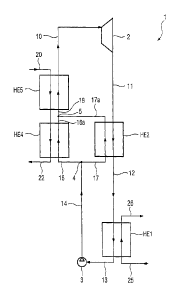
The device 1 shown in FIG. 1 for executing a thermodynamic
cycle process features a (recuperative) heat exchanger HE5,
which on the primary side has hot thermal water 20 from a
geothermal source not shown in any greater detail flowing
through it and is connected on the secondary side on the one
hand to a mixer 5 and on the other hand to a turbine 2. The
turbine 2 is connected on its output side to the secondary
side of a heat exchanger HE2 which is connected in its turn to
CA 02562886 2006-10-13
PCT/EP2004/007443 / 2003P07875W0US
6
the primary side of a condenser HE1. The condenser HE1 is
connected at its primary side output, if nec. via a condensate
tank, via a pump 3 to a separator 4. The separator 4 is
connected on the one hand via the primary side of the heat
exchanger HE2 and on the other via the secondary side of the
heat exchanger HE4 to the mixer 5. The primary sides of heat
exchangers HE5 and HE4 are connected to each other for letting
through hot thermal water 20, with the thermal water first
flowing through the heat exchanger HE3 and then through the
heat exchanger HE4.
A two-substance mixture of water and ammonia which thus
exhibits a non-isothermal evaporation and condensation is used
a working substance in the device 1. The working substance is
present after the condenser HE1 in a liquid state as liquid
working substance flow 13. With the aid of the pump 3 the
liquid working substance flow 13 is pumped at an increased
pressure and a pressurized liquid working substance flow 14
created, which is divided up by the separator 4 into a first
partial flow 16 and a second partial flow 17.
The first partial flow 16 essentially has the same temperature
as the liquid working substance flow 13. The first partial
flow 16 is accepted on the secondary side by the heat
exchanger HE4 and, using heat already created by the cooling
down of the thermal water flow 20 in the heat exchanger HE5,
is partially evaporated and creates a partially evaporated
first partial flow 16a. The second partial flow 17 is accepted
on the primary side by the heat exchanger HE2 and using heat
generated by partial condensation of a expanded working
substance flow 11 accepted on the secondary side, is partially
evaporated and creates a partially evaporated second partial
flow 17a. The partially evaporated first and second partial
flows 16a, 17a are subsequently combined in the mixer 5 into
CA 02562886 2006-10-13
PCT/EP2004/007443 / 2003P07875W0US
7
one partially evaporated working substance flow 18. The heat
exchangers HE2 and HE4 are in this case dimensioned so that
the first and the second partially evaporated partial flow 16a
or 17a have approximately the same temperature and the same
steam content.
The partially evaporated working substance flow 18 is
subsequently accepted on the secondary side of the heat
exchanger HE5 and through cooling down of the hot thermal
water flow 20 accepted on the primary side a completely
evaporated, if necessary partially overheated gaseous working
substance flow 10 is created. The gaseous working substance
flow 10 will subsequently be expanded in the turbine 2, its
energy converted into a usable form, e.g. into current via a
generator not shown, and the expanded working substance flow
11 created. The expanded working substance flow 11 is
partially condensed in the heat exchanger HE2 and a partially
condensed, expanded working substance flow 12 created. The
partially condensed expanded working substance flow 12 is
subsequently condensed in the heat exchanger (condenser) HE1
with the aid of an inflowing cooling water flow 25 and the
liquid working substance flow 13 created. The heat transmitted
by the condensation of the expanded working substance flow 12
to the cooling water flow 25 is discharged by the outflowing
cooling water flow 26.
FIG. 2 shows a cycle calculation for a device for execution of
the thermodynamic cycle process, which essentially corresponds
to the device shown in FIG. 1 and has additionally only been
supplemented by a small number of valves and separator
circuits 27. The following have been chosen as initial
conditions for the calculations:
CA 02562886 2006-10-13
PCT/EP2004/007443 / 2003P07875W0US
8
Temperature Mass flow
Thermal water flow 20 190 C 71 kg/s
Cooling water flow 25 10 C appr. 400 kg/s
The ammonia concentration in the water amounts to 81%.
Table 1 shows for a number of selected flows of the cycle the
result of the cycle calculation, with the power of the heat
exchangers being selected in accordance with Table 2.
Table 1:
Flow Temperature Enthalpy Mass flow Pressure
( C) (kJ/kg) (kg/s) (bar)
187.1 1867.8 30.2 25
13 12.3 -76.52 30.2 5.7
16 13.1 -70.52 13.1 26.01
190 -1737.6 71 20
22 50.59 -2304.1 71 19.22
Table 2:
Heat exchanger Power
HE1 (condenser) 32,51 kW
HE2 18,47 kW
HE4 11.02
HE5 28,87 kW
Total 90,87 kW
The temperature of the first partial flow 16 before entry into
the heat exchanger HE4 amounts to 13.1 C and is thus at about
the same temperature as the pressurized liquid working
substance flow 14 or the liquid working substance flow 13
(12.30C). The electrical power which can be generated under
these conditions with the aid of the turbine 2 amounts to
6925 kW.
FIG. 3 by contrast shows the circuit of a device 30 known in
the prior art as KCS 11 (Kalina Cycle System 11) for executing
a thermodynamic cycle. For better comparison of the known
device 30 with the inventive device shown in FIG. 1 the
= .
CA 02562886 2006-10-13
PCT/EP2004/007443 / 2003P07875W0US
9
corresponding elements or working substance flows are provided
with the same reference symbols. Device 30 differs from the
inventive device shown in FIG. 1 through a additional
(recuperative) preheating heat exchanger HE3 connected on the
primary side between the pump 3 and the separator 4 and on the
secondary side between the heat exchanger HE2 and the
condenser HEl. With the aid of the heat exchanger HE3 the
pressurized, liquid working substance flow 14 is heated by
further partial condensation of the already partially
condensed, expanded working substance flow 12 up to its
boiling point. The first partial flow 16 thus has the
saturated water temperature and is fed at this temperature to
the heat exchanger HE4. Because of this considerably increased
temperature compared to the liquid working substance flow 13
the heat of the thermal water flow 20 can be utilized less in
the heat exchangers HE4 and HE5.
FIG. 4 shows a cycle calculation for a device known from the
prior art which essentially corresponds to the device 30 shown
in FIG. 3 and has additionally only been supplemented by a
number of valves 19 and a separator circuit 27. The same
initial conditions for the calculations are used as those
which were used for the cycle calculation in accordance with
FIG. 2.
Table 3 shows for a number of selected flows of the cycle the
result of the cycle calculation, with the power of the heat
exchangers being selected in accordance with Table 4.
CA 02562886 2006-10-13
PCT/EP2004/007443 / 2003P07875W0US
Table 3:
Flow Temperature Enthalpy Mass flow Pressure
( C) (kJ/kg) (kg/s) (bar)
10 187.1 1867.8 29 25
13 12.13 -77.35 29 5.7
16 66 181.5 14 26.01
190 1730.6 71 20
22 70.06 -2252 71 19.22
Table 4:
Heat exchanger Power
HE1 (condenser) 28,94 kW
HE2 12,74 kW
HE3 7,36 kW
HE4 11,89 kW
HE5 24,26 kW
The electrical power able to be generated in this case amounts
to only 6638 kW. The obtainable electrical power is thus
higher in the case of the inventive cycle according to FIG 1
and 2 by 4.3% than in the case of the cycle known from the
prior art. This additional yield comes from the higher heat
extracted from the thermal water (the temperature of the
outflowing thermal water 22 amounts to only 50.59 C in the
case of the cycle shown in FIG 2 compared to 70.06 C in the
case of the cycle shown in FIG. 4) and the higher mass flow of
the working substance obtainable before entry into the turbine
2 (30.2 kg/s in the case of the cycle shown in FIG. 2 and 29
kg/s in the case of the cycle shown in FIG. 4).
The increased heating surface requirement of 6.25% also
resulting from the increased heat exchanger power results in a
greater need for investment. These increased costs can however
be balanced out in large part by the simplified pipework on
the evaporation side of the turbine 2 and by the omission of
heat exchanger HE2, so that the plant costs overall remain
essentially the same.
. '
CA 02562886 2006-10-13
PCT/EP2004/007443 / 2003P07875W0US
11
The invention has been described above with reference to
preferred exemplary embodiments, but can generally be seen as
not being restricted to these exemplary embodiments. Instead
there is the option of a plurality of variations and
modifications of the invention or of these exemplary
embodiments. For example the number of heat exchangers can be
increased , additional valves and separators can be connected
into the circuit - as also occurs in the circuit example
depicted in FIG. 2. Furthermore the gaseous working substance
flow 10 can be expanded in more than one step, e.g. via two
turbines switched in series.