Note: Descriptions are shown in the official language in which they were submitted.
CA 02563149 2006-09-25
WO 2006/071238 PCT/US2005/004347
Small Form Factor Optical Connector with Thermoulastic Adhesive
BACKGROUND OF THE INVENTION
Field of the Invention
The present invention is directed to an optical connector.
Related Art
Mechanical optical fiber connectors for the telecommunications industry are
known. In recent years, an emphasis has been placed on the use of small-form
factor
(SFF) optical fiber connectors. For example, LC ("Lucent Connectors") optical-
type
connectors have been described in U.S. Patent Nos. 5,481,634; 5,719,977; and
6,318,903.
1o These connectors are used for joining optical fiber segments at their ends
and for
connecting optical fiber cables to active and passive devices. The LC form
factor is ~50%
smaller than the form factors for other conventional optical connectors, such
as ST, FC,
and SC.
However, commercially available LC connectors are not well suited for field
15 installations. Conventional adhesive materials include thermal, anaerobic
or LTV curing
adhesives as well as the use of two-part epoxies and acrylates. For example,
LC
connectors typically use epoxy-based resins (e.g., two part epoxies) for fiber
retention
within the ferrule portion of the connector. These epoxies require about 10 to
15 minutes
to heat cure after application. Once set, the fiber cannot be removed from the
ferrule
2o without breaking the fiber, thus making resetting of the optical fiber in
the ferrule
impractical.
SUMMARY OF THE INVENTION
According to a first aspect of the present invention, a optical connector for
terminating an optical fiber comprises a housing configured to mate with an LC
25 receptacle. The housing comprises a polymer material that does not deform
when exposed
to temperatures of at least 210°C. The optical connector further
includes a ferrule
assembly. The ferrule assembly includes a ferrule portion and a barrel
portion. The
ferrule assembly is preloaded with a thermoplastic adhesive material. The
thermoplastic
-1-
CA 02563149 2006-09-25
WO 2006/071238 PCT/US2005/004347
material can be a polyamide-based hot melt adhesive. The thermoplastic
material can be
an ultra high temperature hot melt adhesive.
According to another embodiment, an optical connector for terminating an
optical
fiber comprises a housing that includes a material that does not deform when
exposed to
temperatures of at least 210°C. The connector further includes a
ferrule assembly having a
ferrule portion and a barrel portion. The ferrule assembly is preloaded with
an ultra high
temperature hot melt adhesive.
The above summary of the present invention is not intended to describe each
illustrated embodiment or every implementation of the present invention. The
figures and
l0 the detailed description that follows more particularly exemplify these
embodiments.
BRIEF DESCRIPTION OF THE DRAWINGS
The present invention will be further described with reference to the
accompanying
drawings, wherein:
Fig. 1 shows an exploded view of an LC connector;
Figs. 2A and 2B show alternative exemplary embodiments of pre-loaded ferrule-
collar-barrel assemblies;
Fig. 3 shows a perspective view of an LC connector mounted in a load adapter
prior to field termination of an optical fiber;
Fig. 4 shows a conventional SC connector; and
2o Fig. 5 shows a conventional FC connector.
While the invention is amenable to various modifications and alternative
forms,
specifics thereof have been shown by way of example in the drawings and will
be
described in detail. It should be understood, however, that the intention is
not to limit the
invention to the particular embodiments described. On the contrary, the
intention is to
cover all modifications, equivalents, and alternatives falling within the
scope of the
invention as defined by the appended claims.
DETAILED DESCRIPTION OF THE EMBODIMENTS
The present invention is directed to a small-form factor optical connector
adapted
to use thermoplastic adhesives, more particularly ultra high temperature
thermoplastic
3o adhesives, for optical fiber retention, insertion, and termination.
-2-
CA 02563149 2006-09-25
WO 2006/071238 PCT/US2005/004347
According to an exemplary embodiment of the present invention, a small form
factor, or LC-type, optical fiber connector includes a preloaded thermoplastic
adhesive.
The use of optical fiber connectors having thermoplastic adhesives provides a
practical
field termination capability. The thermoplastic adhesive utilized can be a
thermoplastic
resin, such as described in U.S. Patent No. 4,984,865, incorporated by
reference herein in
its entirety. In addition, the thermoplastic adhesive can be an ultra high
temperature
(UHT) thermoplastic adhesive material which provides a high softening point
and that is
capable of satisfying environmentally stringent Telcordia GR-326
specifications. In one
aspect, reduced assembly times in field termination applications can be
accomplished. In
1 o an alternative embodiment, larger form factor fiber optic connectors can
include a UHT
thermoplastic adhesive material for more extreme environmental conditions.
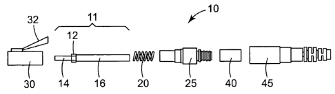
Fig. 1 shows an LC-type optical fiber connector 10 in an exploded view.
Connector 10 includes a housing 30 having a latching arm 32 and an axial or
central bore
to receive ferrule assembly 11. Housing 30 and latching arm 32 are formed or
molded to
be received into an LC receptacle.
According to an exemplary embodiment of the present invention, LC housing 30
is
formed or molded from a high temperature material, such as a high temperature
polymer
(e.g., plastic) material. The high temperature polymer material is capable of
withstanding
temperatures of at least 190°C. In exemplary embodiments, the high
temperature polymer
2o material is capable of withstanding temperatures of at least 210°C,
preferably in the range
of 210°C to about 270°C, without deformation of the body
dimensions. Deformation can
result in the interference with the matability of the connector to another
connector or piece
of equipment. For example, a high temperature material such as Ultem~ XH
6050M,
manufactured by General Electric, of New York, can be utilized.
Connector 10 fiuther includes a ferrule assembly 11. The ferrule assembly can
be
designed to include a ferrule 14, a collar 12 and a barrel 16. Collar 12 can
be used as a
flange to provide resistance against spring 20, to maintain the position of
the ferrule
assembly within housing 30. Ferrule 14 can be formed from a ceramic, glass,
plastic, or
metal material to support an optical fiber inserted therein. The construction
of barrel 16 is
3o described in further detail below.
An optical fiber (not shown) can be inserted through the barrel 16, such that
the
fiber end slightly protrudes from or is coincident or coplanar with the end
face of ferrule
-3-
CA 02563149 2006-09-25
WO 2006/071238 PCT/US2005/004347
14. As described in more detail below, according to an exemplary embodiment of
the
present invention, prior to termination of the optical fiber, a thermoplastic
material,
referred to herein as a "hot melt" adhesive or ultra high temperature (LJHT)
hot melt
adhesive, can be loaded into the ferrule assembly for field termination and
other
applications. Once heated in the field, an operator can insert an optical
fiber to a desired
position. When heat is removed from the connector body, the fiber is quickly
(about 2
minutes or less) set within the ferrule. Should repositioning of the fiber be
required, the
connector can be reheated, and the fiber can be reset within the ferrule.
Connector 10 can further include an insert or connector body 25 that provides
for
1o the retention of the femzle assembly 11 and spring 20 within housing 30.
Connector body
25 can slide over the ferrule assembly and can be secured in place by the
outer connector
housing 30. A crimp ring 40 provides additional axial retention and strain
relief for the
optical cable or optical fiber/jacket. A boot 45 can be further utilized to
protect the optical
fiber cable from bend related stress losses.
Figs. 2A and 2B show alternative embodiments of ferrule assembly 11. In Fig.
2A,
barrel 16' is elongated (e.g., having a length of about 0.25" to about 0.65").
The barrel 16'
includes a preloaded amount of thermoplastic adhesive 50, which resides in
both the barrel
and ferrule 14. As discussed below, the thermoplastic adhesive is heated to a
temperature
sufficient to cause greater flow (e.g., liquefy). The thermoplastic adhesive
can be inserted
2o through barrel end 55 using an injection system. The elongated barrel 16'
can be formed
from a thermally conductive material, such as a metal or high temperature
polymer. The
elongated barrel 16' can aid in the manufacturing process and can withstand
higher
temperatures, as the ferrule assembly needs to be reheated in the field for
fiber insertion,
retention and termination. The barrel 16' can be a press fit assembly to the
ferrule collar
or a threaded assembly. Alternatively, barrel 16' and collar 12 can comprise
an injection-
molded, integral material. In a further alternative, a one-piece collar-barrel
part can be
machined from a suitable metal.
In Fig. 2B, the barrel comprises two main parts, shorter barrel portion 15 and
extension 17. Barrel portion 1 S can be formed from a thermally conductive
material, such
3o as a metal or high temperature polymer and is shorter in length than
elongated barrel 16'.
Extension 17 can be rigid or flexible. For example, a metal or high
temperature polymer
material, e.g., a fluoropolymer tube, can be press fit onto barrel portion 15.
A preloaded
-4-
CA 02563149 2006-09-25
WO 2006/071238 PCT/US2005/004347
amount of thermoplastic adhesive S0, which resides in both the barrel and
ferrule, can be
injected into barrel end 55.
As described above, the LC-type, optical fiber connector includes a preloaded
thermoplastic adhesive. Preloading involves the heating of a hot melt adhesive
and an
injection of a sufficient amount (e.g., volumes about 0.000157 cubic inches to
about
0.00024 cubic inches, or greater) into the ferrule assembly. Typically, an
amount of
liquefied hot melt is injected so that a small amount or bead is exposed on
the end face of
the ferrule. The hot melt material is then cooled (e.g., by removing the
ferrule assembly
from heat), causing hardening. For fiber termination in the field, the LC
fiber connector
1o can be heated utilizing a load adapter, such as load adapter 75 shown in
Fig. 3. Load
adapter 75 is constructed from a material having a high thermal conductivity.
In this
exemplary embodiment, an LC fiber optic connector 10 is loaded with a
sufficient amount
of thermoplastic adhesive, such as a polyamide-based hot melt material or UHT
hot melt
material described herein. The load adapter 75 is then placed in a small oven
configured
t5 to receive and support the load adapter. When the oven is heated, heat is
transferred by
the load adapter to the ferrule and barrel portion of the LC connector. Upon
reaching a
sufficient temperature, the hot melt adhesive softens or liquefies rapidly
(e.g., in about 60
seconds) such that a stripped bare optical fiber can now be inserted through
the barrel
portion of the connector 10. The fiber is inserted to a distance where the
fiber end face is
2o coplanar or protrudes from the end face of the ferrule. When proper
insertion is
completed, heating is ceased, and the fiber is retained (becomes set) in the
ferrule as the
hot melt adhesive hardens. The fiber and ferrule are then polished to remove
excess hot
melt from the ferrule and fiber end face.
In an alternative embodiment, the existing hot melt material or UHT hot melt
25 material described herein can be pre-loaded into other small form factor
and multifiber
connectors, such as an MU-type connector or an MT-type connector.
The thermoplastic adhesive materials of exemplary embodiments of the present
invention will now be described.
For example, existing hot melt adhesives are described in US Patent No.
30 4,984,865. These hot melt materials can operate in temperature ranges from
0° to +60°C,
commensurate with the TIA/EIA 568-B.3 Optical Fiber Cabling Components
Standard for
environments such as inside buildings (Campus or Premise). Due to the nature
of some of
-S-
CA 02563149 2006-09-25
WO 2006/071238 PCT/US2005/004347
these polyamide-based chemistries, at temperatures above 65°C,
pistoning of the fiber in
the connector may occur as the adhesive softens.
According to further exemplary embodiments of the present invention, higher
temperature thermoplastic adhesives, referred to herein as UHT hot melt
materials or UHT
hot melt adhesives, may be utilized. For wider temperature operating
environments such
as Central office and Outside Plant, adhesives must have an operating range of
~0° to
+85°C to meet the Telcordia GR-326 CORE and GR-1435-CORE Standards.
Traditionally, it was believed that adhesives needed to have a glass
transition temperature
("Tg") that was higher than the upper limit of the operating temperature range
(i.e. epoxy
1o adhesives). Further, it has been generally held and empirically proven that
having the Tg
in the middle of the operating temperature range could result in inconsistent
optical
performance due to nonlinear changes in the physical properties of the
adhesive at
temperatures above the Tg, such as the coefficient of thermal expansion and
flow behavior
of the adhesive, leading to fiber pistoning. However, exemplary samples tested
below
should not exhibit such pistoning because of their creep-resistance
properties.
Exemplary embodiments of the present invention provide the use of UHT hot melt
fiber optic connectors in an increased number of applications due to enhanced
thermal and
humidity resistance. These properties allow for installers in outside plant
applications to
make fiber optic connections quickly and in a straightforward manner. The UHT
materials can be utilized in an LC connector, such as is shown in Fig. 1.
According to an
alternative embodiment, the UHT materials can be pre-loaded in larger form
factor
connectors, such as SC connector 80 and FC connector 90 (shown in Figs. 4 and
5,
respectively), and ST connectors.
UHT hot melt materials can include polyamides, and polyesters which can have
semi-crystalline properties. For example, UHT hot melt adhesives may be
selected from
materials such as Macromelt~ polyamide resins (TPX-12-692, 6300, TPX-16-346 or
TPX-16-192 available from Henkel), other similar polyamides (PA) available
from Loctite
or Hysol, polyetherimides or polyesters including polyetheylene terephthalate
(PET),
polybutylene terephthalate (PBT), or copolymers thereof (Dynapol S394 (PET)
and
3o Dynapol 5361, Dynapol S341 or Dynapol S341HV (PBT) available from Creanova
or
Vitel 4255 (PBT) available from Bostik). The physical characteristics of
several different
-6-
CA 02563149 2006-09-25
WO 2006/071238 PCT/US2005/004347
types of UHT hot melt adhesives are shown below in Table 1. A comparison hot
melt
material, similar to that described in U.S. Patent No. 4,984,865 is also
listed.
TABLE 1
SofteningCreep Tg Shore Water Modulus
D
C Pol Point Resistance HardnessAbso ViscosiG'
stallini mer tion at
8sC
C C (C 2-da7-daP Pa
X-12- 2s-60
692 Some PA 206-216178-184-1473/62 0.2%+0.4%at
240C
acromelt 25-s0
6300 Some PA 190-20018s-190-2362 0.1%+0.3%at 1.1E+07
240C
X-16- 2s-s0
46 Some PA 18s-19s165-175-2070-74 0.2%+O.s%at
210C
X-16- 3s-s0
192 Some PA 167-170167-162-1768-70 0.3%+0.6%at
210C
ynapol 100
S 394 Hi 28 PET 182-189 -16s0 0.9%0.9%at 1.1E+07
h 200C
ynapol
S 341 Med.22 PBT 1s0-lss -28s6 0.7%0.6% 4.3E+07
HV
itel
copolyester 7s0
2ss Med.22 PBT 1s6 -8 s3 0.3%0.3%at 1.1E+07
215C
Current
of Melt 20
dhesiveNone PA 170-190 6s 61 0.6%0.9%at 7.0E+06
190C
+ water absorption after 1 day
s As shown, these exemplary UHT hot melt materials are not limited to
polyamide
materials. These UHT hot melt materials can also have one or more of the
following
properties:
a) a melt viscosity of 1000-20,000 cp in the working temperature range (210-
250°C);
to b) a Shore D hardness of SO-85 at room temperature;
c) 15 - 35% crystallinity in the adhesive to provide superior adhesive
stability
in fiber optic connectors;
d) a Young's Modulus greater than about 1 x 10' psi within the operational
temperature of the connector; and
1 s e) enhanced polishing characteristics resulting in less smearing of the
adhesive and more precise control of the fiber-to-ferrule profile.
The Shore D hardness property described above represents a substantial
increase in
Shore D hardness range compared to some polyamide-based hot melt materials,
which
CA 02563149 2006-09-25
WO 2006/071238 PCT/US2005/004347
have Shore D hardness values of greater than 60. For example, some exemplary
UHT hot
melt material described herein have a Shore D hardness of about 50 to about
57. In
addition, UHT hot melt adhesives of the exemplary embodiments can be utilized
in a wide
operational temperature range, enabling a broad range of uses.
According to one embodiment, an exemplary LTHT hot melt adhesive can be semi-
crystalline in structure, having a Tg within the standard operating window. In
addition to
having suitable thermal performance, the UHT hot melt adhesives of exemplary ,
embodiments can possess enhanced polishing characteristics over other hot melt
adhesives.
In addition, the exemplary UHT hot melt adhesives exhibit extremely low creep
resistance levels. As a result, fiber protrusion requirements can be relaxed,
making the
polishing process more robust. As an example, a target fiber protrusion range
for lower
softening point hot melt adhesives is about 0.5 p,m to 1.5 pm, which ensures
sufficient
optical contact. This protrusion range can limit the amount of polishing
performed in the
field. Over polishing can occur once the existing hot melt bead is removed
from the
connector end face.
UHT hot melt materials provide for straightforward polishing. For example,
with
exemplary UHT hot melt materials, the target fiber protrusion range can be
similar to that
commonly utilized for epoxy-based fiber connectors: +50 nm to -125 nm, as is
described
in Telcordia GR-326 (& IEC Connector Specs). This protrusion range is
considered
virtually 'coplanar' (-125 nm is a slight undercut), with the radius of
curvature that results
on the ceramic ferrule end face. As a result, the ceramic ferrule end face can
act as a
polish stop. With a suitable final polishing media, such as a 20 nm Si02
lapping film (or
fine Aluminum oxide lapping film), many extra polishing strokes can be made to
remove
scratches, without exceeding the maximum fiber undercut specification of 125
nm. In
addition, the UHT hot melt materials (when set) provide a sufficiently hard
material that
can be rapidly removed when polishing, without spalling or peeling away.
Thus, by utilizing a UHT hot melt material in a small form factor fiber optic
connector, the combination of straightforward polishing and rapid removal rate
of the
3o UHT hot melt materials (as compared with conventional epoxies) provides an
advance
over the current state of the art with respect to field mount polishing.
Presently, small
form factor ceramic-ferruled connectors such as LC or MLJ are supplied with
small flat
_g_
CA 02563149 2006-09-25
WO 2006/071238 PCT/US2005/004347
end faces (e.g., ~0.7 to 0.9 mm) that are perpendicular to the axis of the
ferrule, with no
radius. Through polishing with a succession of lapping films from coarse to
fine, which is
required to remove the epoxy-type (i.e., hard) adhesives, a radius is formed
and
subsequently the fiber is polished-out to a fine surface finish. When
polishing to meet the
specifications described in Telcordia GR-326 (& IEC Connector Specs.), the
required
Apex Offset (50 p.m max.) can be difficult to control by hand using a
conventional 1.5"
diameter field polishing jig. Additionally, the radius of curvature of the
polished fiber end
can become less than 7 mm (the min. radius requirement in GR-326 & IEC
Connector
Specs.) because the conventional ferrule extension through the polishing jig
is excessive,
1o which leads to radii as small as 3 mm and Apex Offsets as high as 80 pm.
Other polishing techniques can be utilized with UHT hot melt fiber optic
connectors. For example, UHT hot melt material can be removed in a one-step 2
pm
A1203 Multimode process or a two-step SM Process, utilizing 20 nm Si02 as the
second
step. Thus, the ceramic ferrule can be factory pre-radiused to a desired
target range of
approximately 8-15 mm with an Apex Offset of 30 pm maximum. A precise
polishing jig
that controls the ferrule extension through the bottom of the jig can be
utilized - thus, the
radius of curvature can be maintained along with the Apex Offset in a field
polishing
process.
EXAMPLES AND TESTS
2o In a first performance test, sample UHT holt melt adhesives (in this test,
Dynapol
materials) were prepared. To test the performance of the Dynapol hot melt
adhesives in its
operating environment, fiber optic cables were prepared as follows: several
lengths of
Siecor 62.5 multimode fiber cable (6 m in length) were prepared by removing
1.25 inches
of the jacketing material to expose the "Kevlar" fibers. The Kevlar fibers
were separated
to expose the buffer coated optical fiber. About 1.125 inches of the buffer
coating was
stripped from the optical fiber to expose the bare glass fiber. The fiber was
wiped with
isopropyl alcohol to clean the exposed glass. The Kevlar fibers were then
trimmed to a
length of 0.25 inches and redistributed evenly around the buffer.
An adhesive filled ST connector was placed into an oven (available from Kitco,
in
3o Virginia) and heated to about 265°C until molten. The bare optical
fiber was then inserted
through the axial bore in the ceramic ferrule to a position where the fiber
end face
-9-
CA 02563149 2006-09-25
WO 2006/071238 PCT/US2005/004347
protruded past the ferrule end face, and the Kevlar Fibers and j ticketing
material entered
the body portion of the connector and contacted the adhesive. It is noted that
the bead of
hot melt adhesive on the ferrule end face provides lateral support for the
fiber during the
cleaving process. The cleaved fiber was then polished with a 2 ~m aluminum
oxide
lapping film (available from 3M Company, # 60-6500-2346-2) to a specified
length.
Polishing can be performed to generate a fiber end face that is coplanar with
the ferrule
and face. Alternatively, polishing can be performed to create a fiber
protrusion up to
about 1.5 pm. An interferometer (available from Direct Optical Research
Corporation -
DORC ZX-1 Mini PMS) can be used to measure the fiber protrusion after
polishing.
to These exemplary UHT hot melt adhesive materials can provide favorable
polishing
in part because localized heating of the UHT hot melt adhesive material during
polishing
does not exceed the softening point of the materials.
In a first polishing test, a coplanar polish was performed using an SC
connector
preloaded with an exemplary UHT hot melt material. Table 2 shows performance
test
15 results for coplanar polished thermoplastic adhesive materials (No.
Passed/No. Tested):
TABLE 2
Material Temperature Humidity Heat Step
Cycle
-10C - -40C - 40C/95%1ZH75C/95%RH 60C - 120C
+60C +80C 4 da s 4 da s
Dynapol53945/5 5/5 5/5 ' S/5 4/5
Dynapol53615/5 5/5 5/5 5/5 5/5
These samples underwent the following test regime: -10°C -
+60°C temperature
cycle, 4 days at 95%RH 40°C, -10°C - +60°C temperature
cycle, 4 days at 95%RH 75oC,
20 -40°C - +80°C temperature cycle and finally a 60°C -
120°C heat step test. The
environmental test of Table 2 was performed consecutively on the same set of
connectors.
As Table 2 indicates, all temperature cycling and humidity samples passed the
tests, which
are a combination of TIA/EIA 568-B.3, Telcordia GR-326, and even exceeding GR-
326
by testing to a temperature of 120°C.
25 In a second polishing test, a standard LC polishing jig that normally
allows the
ferrule to protrude 0.8 mm was modified so that the ferrule would only
protrude 0.3 mm.
Polishing was accomplished by using a 70 Dur. (Shore A) elastomeric polishing
pad
beneath the lapping film. The radius on the test samples was held to about 7.5
to 11 mm,
-10-
CA 02563149 2006-09-25
WO 2006/071238 PCT/US2005/004347
with Apex Offsets ranging from 10 - 35 pm. The radius can be further adjusted
by using a
slightly higher Durometer Pad or by changing the ferrule extension from the
jig base.
In another performance test, sample UHT holt melt adhesives (in this test,
Henkel
materials) were prepared. To test the performance of the Henkel 12-692
adhesive, 15
connectorized pairs of SM SC/LJPC connectors were submitted to complete
Telcordia GR-
326 environmental tests. All SM SC/UPC connectors were preloaded with UHT hot
melt
as described above and all optical fibers were terminated in the manner
described above.
All test samples passed the optical requirements of < 0.3 dB change in Loss
and > 55 dB
reflection.
to In another performance test, sample UHT holt melt adhesives were utilized
in a
test of 7 connectorized pairs of LC Connectors. These connectors were
preloaded with
exemplary UHT hot melt adhesives (in this test, Henkel materials) and
terminated in the
manner described above. All of the test samples passed Telcordia GR-326
Engineering
(screening) tests, which had the same temperature limits, but shorter test
durations to
accelerate feedback.
- The present invention should not be considered limited to the particular
examples
described above, but rather should be understood to cover all aspects of the
invention as
fairly set out in the attached claims. Various modifications, equivalent
processes, as well
as numerous structures to which the present invention may be applicable will
be readily
2o apparent to those of skill in the art to which the present invention is
directed upon review
of the present specification. The claims are intended to cover such
modifications and
devices.
-11-