Note: Descriptions are shown in the official language in which they were submitted.
CA 02563714 2006-10-18
WO 2005/104697 PCT/US2005/013613
INTERFACE DEVICE AND PROTOCOL
BACKGROUND OF THE INVENTION
The invention relates generally to injector and imaging equipment for
performing diagnostic imaging on a patient, and more particularly to an
interface
device for facilitating communication between an injector device and imaging
equipment.
In many medical diagnostic procedures, a physician or other person injects
a patient with a fluid, such as a contrast media, that is detectable with
diagnostic
imaging equipment. In recent years, a number of injector-actuated syringes and
powered injectors for pressurized injection of fluids have been developed for
use in
diagnostic imaging procedures such as angiography, computed tomography,
ultrasound, and NMR/1VIRI. In general, the powered injectors and imaging
equipment may be monitored and operated with separate interfaces.
The imaging equipment may expose a patient to a determined amount of
energy after inj ection of the fluid. In many circumstances it may be
desirable to
synchronize the timing of the injection to the exposure of imaging energy. For
instance, during a computed tomography (CT) scan, a patient may be initially
administered a specified volume of contrast media, (approximately 100 cc) at a
desired flow rate (e.g., approximately 3 cc/sec) intravenously using an
injector.
Depending upon the fluid dynamics of the contrast media being administered to
the
patient, the particular physiology of the patient, and the anatomical region
of the
patient being imaged, the patient may be exposed to the imaging equipment's
energy for some optimal period of time. The use of separate interfaces for
both the
injector and the imaging equipment may make synchronization between the
devices difficult.
CA 02563714 2006-10-18
WO 2005/104697 PCT/US2005/013613
In general, the injection device and the imaging equipment may be located
in an imaging room, and the interfaces may be located in a separate imaging
control room. The combination of the imaging room and the imaging control room
is commonly referred to as an imaging suite. User interface controls for the
injector device and the imaging equipment may be primarily, but not always be
limited to features associated with patient set-up prior to, or during the
early part of
exposing the patient to the energy of the imaging equipment. To perform the
diagnostic procedure, clinicians) in the imaging control room may have to
program, initiate, monitor, control, and terminate the imaging procedure on
two
different interfaces. In some cases it may be necessary for the clinicians) to
monitor and control the two interfaces concurrently. There may be situations
where the lack of synchronization may result in starting the imaging equipment
too
early or too late. As a result, image quality may be poor and it may be
necessary to
repeat the procedure. Restarting the procedure may not desired because it
makes
the overall process more expensive, less efficient, and the patient may have
to be
re-exposed to the imagining equipment energy and a re-dosing of injected
contrast.
media.
Thus, there still exists a need for a device and method for concurrently
monitoring and controlling an injector device and imaging equipment from a
single
interface.
BRIEF SUMMARY OF THE INVENTION
In one alternative embodiment, the present invention is directed to an
interface device and system for establishing an operating interface between an
injector device and diagnostic imaging equipment. In one alternative
embodiment,
the interface device may permit an operator to concurrently operate and
control
both the injector device and the imaging equipment. In some embodiments the
interface device may permit the injector system and the imaging system to
communicate information regarding their current and future operational status
with
each other. As a result, the interface device may be used to synchronize the
operation of the imaging equipment and the injector device.
CA 02563714 2006-10-18
WO 2005/104697 PCT/US2005/013613
In one alternative embodiment, the interface device may be adapted for
facilitating conununication between the inj ector device and the diagnostic
imaging
equipment. In one embodiment, the interface device may comprise a control unit
having one or more stored imaging equipment operational protocols that may be
used to operatively control the operations of the imaging equipment. In one
alternative embodiment, the interface device may include a dedicated input
that
may be in communication with the control unit and may be adapted for receiving
information from the imaging equipment, and a dedicated output that may be in
communication with the control unit and may be adapted for sending information
from the control unit to the imaging equipment. The interface device may also
include one or more input/output interfaces that may be in communication with
the
control unit and may be adapted for sending and receiving information between
said control unit and the injector device.
In. one alternative embodiment, the stored operational protocols may
include operational parameters such as tube current, tube voltage,
collimation,
pitch, detector configuration, rotation, pause, scan delay, start, and stop.
In one
alternative embodiment, the interface device may use the operational protocols
to
synchronize the operation of the imaging device with the injector device. In
one
embodiment, the interface device may be used to communicate current status of
the
injector device to the imaging equipment and vice versa. As a result, the
imaging
equipment and the injector may know the status of each device and may be
capable
of stopping or starting the injection or the diagnostic imaging at a desired
time.
Tn one alternative embodiment, the inj ector device and the imaging
equipment may be able to communicate with each other directly or through the
interface device via a communcations protocol comprising binary logic signals.
In
some embodiments, the binary logic signals may comprise one or more of a low
strength signal, a high strength signal, an oscillating signal that oscillates
between
low and high signal strength, and combinations thereof. The binary logic
signals
may be used to communicate various operational states of the inj ector device
and
the imaging equipment. In one alternative embodiment, the control unit of the
interface device may be configured to convert the binary logic signals into a
format
that may be recognizable by the control console and/or the inj ector device.
CA 02563714 2006-10-18
WO 2005/104697 PCT/US2005/013613
In one alternative embodiment, the invention may comprise a system for
performing diagnostic imaging comprising an injector device adapted for
injecting
a contrast media into a patient; a piece of diagnostic imaging equipment for
producing diagnostic images; an interface device operatively connected to the
injector device and the imaging equipment, and capable of cornznunicating
information between the injector device and the imaging equipment; and a
control
console operatively connected to the interface device. hl one alternative
embodiment, the interface device may comprise a control unit capable of
processing information from the imaging equipment and the injector device; one
or
more stored operational protocols for operating the imaging equipment; and one
or
more input/output interfaces for communicating information between the
injector
device and the imaging equipment.
In some embodiments, the interface device may comprise a stand-alone
device that may be capable of performing real time analysis of communications
between the injector device and the imaging equipment. In one embodiment, the
interface may be able to synchronize the functions and operations of the inj
ector
device and the imaging equipment in real time. As a result, the need for re-
injections or additional scanning procedures may be reduced. Other features of
the
present invention are set forth in the drawings and detailed description.
BRIEF DESCRIPTION OF THE SEVERAL VIEWS OF THE DRAWINGS)
Having thus described the invention in general terms, reference will now be
made to the accompanying drawings, which are not necessarily drawn to scale,
and
wherein:
FIG. 1 is a pictorial illustration of a prior art imaging suite having
separate
remote consoles for the injector device and the imaging equipment;
FIG. 2 is a non-limiting description of one alternative embodiment of the
present invention showing a pictorial illustration of a diagnostic imaging
system
having an interface device for facilitating communication between the injector
device and the imaging equipment;
FIG. 3 is a non-limiting description of one alternative embodiment of the
present invention showing a schematic illustration of the interface device;
CA 02563714 2006-10-18
WO 2005/104697 PCT/US2005/013613
FIG. 4 is a non-limiting description of one alternative embodiment of the
present invention showing a block diagram of at least one alternative imaging
system having an interface device;
FIG. 5 is a non-limiting description of one alternative embodiment of the
S present invention showing a block diagram of at least one alternative
imaging
system having an interface device;
FIG. 6 is a non-limiting description of one alternative embodiment of the
present invention showing a block diagram of at least one alternative imaging
system having an interface device;
FIG. 7 is a non-limiting description of one alternative embodiment of the
present invention showing a block diagram of at least one alternative imaging
system having an interface device;
FIG. 8 is a non-limiting description of one alternative embodiment of the
present invention showing a block diagram of at least one alternative imaging
I S system having an interface device;
FIG. 9 is a non-limiting description of one alternative embodiment of the
present invention showing a graphical representation of a binary logic signal
that
may be generated by the injector device to communicate information to the
imaging equipment; and
FIG. 10 is a non-limiting description of one alternative embodiment of the
present invention showing a graphical representation of a binary logic signal
that
may be generated by the imagiilg equipment to communicate information to the
injector device.
DETAILED DESCRIPTION OF THE INVENTION
The present invention now will be described hereinafter with reference to
the accompanying drawings. The invention may be embodied in many different
forms and the drawings and descriptions herein should not be construed as
limited
to the embodiments set forth herein. Like numbers refer to like elements
throughout.
With reference to the drawings, FIG. 1 generally illustrates a conventional
computed tomography (CT) imaging system arrangement located in an imaging
CA 02563714 2006-10-18
WO 2005/104697 PCT/US2005/013613
suite 10 The CT imaging system typically includes a powered CT inj ector I5
and
CT imaging equipment 20 ("scanner") that are both normally located in an
imaging
room 25. The CT inj ector 15 and CT scanner 20 are usually both separately
controlled by different remote consoles 17, 22, respectively. The remote
consoles
17, 22 may be located externally of the imaging room in a separate control
room
30. As shown, the imaging suite may include a viewing window 32 through which
the operator may view the procedure. The imaging room 25 may be shielded from
electromagnetic interference. Communication lines 19, 24 may separately
connect
each device to its respective control console. As should be evident from
FIG.1,
under the conventional system, the injector and scanner may require separate
remote consoles and operation.
In one alternative embodiment, the invention is directed to an imaging
system having an interface device for facilitating communication between an
injector device and a piece of imaging equipment. The injection/imaging system
may comprise an injector system and imaging system that are in communication
with and operatively controlled by an interface device.
An injector system may include an injector device that can be used to
administer an effective dosage of a contrast medium and a control interface
that is
operatively connected to the injector device. The injector system may have one
or
more control interfaces. The control interface may send and receive data to
and
from the injector device. The injector device can be any type of injector
mechanism that may be used to deliver a contrast medium into a patient or subj
ect
(e.g., E-Z-EM EMPOWER CT Injector). The imaging system may be comprised
of an imaging control console, an imaging device or equipment that can be used
to
monitor and display the contrast medium within a patient or subject, acquire
internal images of a patient or subj ect, and to provide other diagnostic data
to a
control console or storage media. The imaging system may have an imaging
interface that may be operatively comZected to the imaging equipment.
The term "contrast medium" includes any suitable medium, that can be
injected into an individual or subject to highlight and/or identify selected
areas of
the individual's body. Contrast mediums may include, but are not limited to a
radio opaque iodinated liquid compound, gadolinium liquid compound, saline
6
CA 02563714 2006-10-18
WO 2005/104697 PCT/US2005/013613
media, flush media, and the like, and any combination thereof. A contrast
medium
may be used in conjunction with an imaging device that is used to perform
medical
diagnostic imaging such as CT scans, MRI, ultrasound, etc.
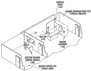
In one alternative embodiment, the invention is directed to an interface
device that may be used to facilitate communication between an injector device
and diagnostic imaging equipment. In this regard, FIG. 2, illustrates an
alternative
embodiment of the invention depicting an imaging suite wherein a diagnostic
imaging system may include an interface device 100 that may help facilitate
communication between the injector device 110 and the imaging equipment 120.
In one embodiment, the interface device may be a stand-alone device that may
function as an intermediate between the injector device and the imaging
equipment
so that both devices may know the status of the other device in real-time. In
some
embodiments, the interface devised may be disposed in either the control room
or
the imaging room. Although the description of the invention primarily
discusses
the invention with regards to a CT imaging system, it should be recognized
that the
invention is not limited to CT imaging, and that the invention encompasses a
variety of diagnostic imaging procedures which include, but is not limited to,
magnetic resonance (MR), ultrasound, angiographic, positron emission
topography
(PET), fluoroscopy, etc.
In one alternative embodiment, the interface device may comprise a stand-
alone device that may permit the inj ector device to know the current status
of the
imaging equipment, and the imaging equipment to know the current status of the
injector device. In some embodiments, the interface device may be capable of
real-time synchronization of the injector device and the imaging equipment. In
one
alternative embodiment, the interface device may include a microprocessor that
may be capable of communicating information received from the imaging
equipment or an imaging control console into a format recognizable by the
injector
device. Such imaging equipment information may include one or more of current
status of the imaging device; whether the imaging equipment is in the process
of
performing a diagnostic scan, whether the imaging scan has halted, and the
like. In
some embodiments, the microprocessor may be able to receive information from
an injector device and convert the information into a format recognizable by
the
CA 02563714 2006-10-18
WO 2005/104697 PCT/US2005/013613
imaging equipment. Such injector information may include one or more of:
inj ector status; whether the inj ector is armed whereby inj ector
configuration will
permit injection; whether the injector is in the process of injecting; whether
the
injection has stopped or failed to inject, and the like.
S A stand-alone interface device having a means of processing information
separate from the either the injector console or the imaging console may help
improve real-time synchronization between the injector device and the imaging
equipment and reduce any latency in processing the information from the inj
ector
device and/or imaging equipment. hi some embodiments, each manufacturer of
diagnostic imaging equipment may develop and determine its own unique
communication protocols for communicating with the imaging equipment. Such
unique communication protocols may sometimes cause communication delays or
latency issues within the control console. The use of a stand alone interface
device
may help reduce or eliminate such latencies or delays because the interface
device
may be dedicated to receiving and sending communications between the injector
device and the imaging equipment. As a result, the interface device may permit
the injector device and the imaging equipment to know the status of the other
device in real-time. This information may permit real-time synchronization of
the
inj ector device and the imaging equipment.
With reference to FIG. 3, an alternative embodiment of the interface device
100 is schematically illustrated. In one alternative embodiment, the interface
device 100 may include a control unit 150, a memory component 152, a dedicated
input 154 that may be adapted for receiving data from an imaging device or an
imaging control console, a dedicated output 156 that may be adapted to
communicate injector device status to an imaging device or an imaging control
console, one or more (I/O) interfaces 158,160 that may be adapted for
communicating with a remote injector console andlor the injector device. As
shown in FIG. 3, the control unit may be operatively connected to the memory
component, dedicated input, dedicated output, and the one or more T/O
interfaces.
In some embodiments, the dedicated input may be capable of receiving
information from the imaging equipment, such as current status, operational
state,
and the like. Tn one alternative embodiment, the connection between the
dedicated
CA 02563714 2006-10-18
WO 2005/104697 PCT/US2005/013613
input and the dedicated output on the imaging equipment may comprise a hard
wired connection. In some embodiments, the connection 128 between the
dedicated input 154 and the control unit 150 may be electrically isolated from
the
connection 126 between the dedicated output 156 and the control unit 150. For
example, such logic level signals carried on 122 and 124 may be managed
through
a layer of isolation between the connections 154 and 156 and the control unit
150.
Although not explicitly shown in the diagram in FIG. 3, opto-isolation
components
could be used to isolate signals 122 and 124 from one another as well as
establishing isolation between the control unit 150 and the imaging equipment
120.
The interconnection of the imaging device 100 with the imaging equipment 120
at
connection points 154 and 156 may be made with a cornlnercially available type
comlector. Generic connectors meeting this need may include, for example,
commercially available D-subminiature plug socket type connectors and the
like.
In one alternate embodiment, the dedicated output may be capable of
sending information to the imaging equipment, such as the status of the inj
ector
device, whether the injector is stopped, armed, injecting, etc. In some
embodiments, the connection between the dedicated output and the control unit
may be electrically isolated from the connection between the dedicated input
and
the control unit.
In some embodiments, the hard wire connection fox the dedicated input and
output interfaces may include multiple channels that may each be configured to
perform different functions. In one alternative embodiment, the dedicated
input/output interfaces may comprise a mufti-channel connection wherein the
connector to the interface device comprises e.g., a 9 to 15 pin socket. The
individual pins of each socket may be capable of performing different
functions
such as, e.g., communicating one or more of: injector status, starting
injecting, stop
injection, stop diagnostic imaging, start diagnostic imaging, and the like.
In an alternate embodiment, the one or more I/O interfaces 158,160 may be
adapted to send and retrieve information from the injector device and/or the
injector remote console. In some embodiments, the I/O interface may comprise
wired or wireless connectivity means such as I2C, ACCESS.bus, RS-232,
universal serial bus (USB), TEE-488(GPIB), LAN/Internet protocols such as
CA 02563714 2006-10-18
WO 2005/104697 PCT/US2005/013613
TCP/IP, wireless means such as infrared (IR) communication, 802.11x, and
Bluetooth, etc, and combinations thereof. In some embodiments, the I/O
interface
may comprise a combination of wired and wireless connectivity means. In one
alternative embodiment, the connection between the interface device and the
injector device may include a serial connection, such as RS-232.
In some embodiments, the control unit 150 may be in the form of an
embedded system comprising a microprocessor or microcontroller configured to
perform one or more functions such as converting the imaging equipment
communication protocols into a format recognizable by the injector device, or
using stored operational protocols to synchronize the injection and imaging
processes. As used herein, the term "microcontroller" refers to a
microprocessor
on a single integrated circuit intended to operate as an embedded system. The
microcontroller may also include memory components such as RAM, EEPROM,
and PROM, internal timers, and I/O port interfaces. The control unit may
include
an internal memory component (not shown) that may be an integral part of the
control unit. In some embodiments, the control unit may include executable
program modules that may be embedded within the internal memory component of
the control unit.
In some embodiments, the controller may include a memory component
152 that may be external or internal to the control unit. In one alternative
embodiment, the memory component may be configured to buffer information
from the imaging equipment and/or the injector device. In some embodiments,
the
memory component may include flash memory. Flash memory refers generally to
a type of nonvolatile memory that can be erased and reprogrammed in units of
memory called blocks. The capacity of the memory component can be varied
depending upon the desired amount of information that can be stored. In some
embodiments the capacity of the memory component may comprise e.g., 64K,
128K, 256K, 512K, 1028 K, 2056 K, or greater memory blocks.
As discussed above, each manufacturer of diagnostic imaging equipment
may develop and determine its own unique communication protocols for
communicating with the imaging equipment. In some embodiments, the interface
device may be programmably configured to store multiple communication
to
CA 02563714 2006-10-18
WO 2005/104697 PCT/US2005/013613
protocols in an internal or external memory component. Stored communication
protocols may include, but is not limited to one or more protocols for GE,
Phillips,
Siemens, etc., imaging equipment. The stored communication protocols may
permit the interface device to be used with a variety of different imaging
S equipment. In one alternative embodiment, an operator may be able to select
a
desired imaging equipment communication protocol from the inj ector remote
console, which may be in cormnunication with the interface device. After an
operator selects the appropriate communication protocol, synchronization of
the
injector and scanner may occur. In addition, in some embodiments the
microprocessor may be reprogrammable to include additional communication
protocols.
In one alternative embodiment, the manufacturers of the imaging
equipment may each develop their own unique operational protocols for
operating
the imaging equipment. In the context of the invention "operational protocol"
1 S includes but is not limited to one or more operating parameters for the
imaging
equipment or the injector device that may be used to perform specific tests
and that
can be grouped together and stored for later recall. In some embodiments, the
operational protocol may include a grouping of program modules that are used
by
the control unit of the interface device to instruct the imaging equipment to
perform a desired function at a desired time. In the case of a CT scanner,
such
operating parameters may include, but are not limited to, kV (voltage applied
to an
X-ray tube, mA (x-ray tube current) detector collimation, pitch (table speed)
gantry
rotation speed, detector configuration (number of detector slices number and
resultant size), automatic control parameters (dose), timed pauses, holds,
and/or
delays, and the like, and any combination thereof. In some embodiments, the
imaging equipment operational parameters may be displayed on a remote control
console. In one alternative embodiment, the operating parameters may be
manipulated to optimize the imaging and detection data.
In some embodiments, the interface device may be capable of storing
multiple operational protocols for multiple manufacturers of imaging
equipment.
In one alternative embodiment, an operator may select a desired operational
protocol for the imaging equipment from a menu screen on the remote console.
11
CA 02563714 2006-10-18
WO 2005/104697 PCT/US2005/013613
When a desired operational protocol is selected, the remote console may
instruct
the interface device to recall the selected operational protocol from its
memory
component. In some embodiments, the stored operational protocol may then be
used by interface device to instruct the imaging equipment to perform one or
more
operations at a desired time, such as when to begin the diagnostic imaging.
For
example, in one embodiment, an operator may select an operational protocol for
the imaging equipment that specifies that the diagnostic imaging begins at a
predetermined time after injection of a contrast media has begun. The
interface
device, using the selected operational protocol, may monitor the timing of the
injection and may instruct the imaging equipment to begin diagnostic imaging
at
the desired time. As a result, the interface device may help facilitate
synchronization of the inj ector device arid the imaging equipment and may
help
reduce or eliminate the need to have an operator monitoring two consoles to
make
sure that the sequences of injections and scanning are done at the appropriate
time.
Additionally, in some embodiments, the interface device may be used to
monitor the status of the injector device and the imaging equipment to ensure
that
the sequence of operational parameters for the injection device and the
imaging
equipment are carried out at the appropriate ime. For example, the interface
device may be used to monitor whether the imaging equipment is in the proper
state for performing a diagnostic imaging before the injector device is armed.
This
may help reduce or eliminate the possibility of inj ecting a media into a
patient
prematurely before the imaging equipment is ready to begin diagnostic imaging.
As discussed above, in some alternative embodiments, the interface device
may be reprogrammable so that an operator may download additional operational
protocols or edit existing protocols in the interface device.
In some embodiments, the interface device may also include stored
operational protocols for the injector device. ~ The specific operational
parameters
may be dependent upon the specific media being injected, the part of the
subject
being imaged, and the like, and any combination thereof. The media may include
contrast media, saline media, and the like, and any combination thereof. Such
operational parameters include, but are not limited to, phases, flow rates,
volumes,
pressures, timed pauses, hold, and delays to x-ray exposure. In one embodiment
of
12
CA 02563714 2006-10-18
WO 2005/104697 PCT/US2005/013613
the present invention, stored protocols allow operators to quickly recall
optimized
parameters that can be used in subsequent tests. As a result, the efficiency
of the
test and imaging quality can be improved.
Alternatively, the operational parameters for the injection device and the
S imaging equipment may be combined into a single operational protocol. In
some
embodiments, the combined operational protocol can be displayed on a single
display. An operator can use a combined operational protocol to operate the
injector device and the imaging equipment. These combined operational
protocols
may permit an operator to efficiently recall operation parameters for both
injector
device and the imaging equipment that have been optimized for a specific test:
As
a result, the efficiency of the test and the image quality can be improved.
In some embodiments, the interface device may be remotely programmable
and include separate communications hardware, such as an ISP programming head,
for programming the interface device. The interface may also include an I/O
buffer for temporarily storing information that can be sent to a manufacturer
of the
imaging equipment at a desired time.
The interface device may be powered from a variety of different power
sources including, but not limited to, a separate AC power supply, a local
battery,
or from the imaging device or injector device through a wired connection such
as a
serial connection.
In some embodiments, the interface device may include a means for
electrically isolating signals received from the imaging equipment from the
inj ector device, and vice versa. In some cases, medical devices, such as the
imaging equipment may be required by the FDA to maintain electrical isolation
between electrical circuits and other devices. Electrical isolation may be
accomplished in a variety of way including wireless communication between the
interface device and either the imaging equipment or injector device, or both.
In
one alternate embodiment, the interface device may include one or more
optically
coupled isolators that may be used to establish circuit isolation between the
imaging equipment, the injector device, the dedicated input for the imaging
equipment, dedicated output for the imaging equipment, or combinations
thereof.
13
CA 02563714 2006-10-18
WO 2005/104697 PCT/US2005/013613
FIGS. 4 through 8, are block diagrams that illustrate alternative
embodiments of an imaging system having an interface device that may permit
communications between an injector device and the imaging equipment. In FIG. 4
an alternate embodiment of the invention is illustrated wherein the interface
device
100 may be disposed between a control console 130 and the injector device 1100
and the imaging equipment 120. The inj ector device 110 and the control
console
130 may be connected to the interface device via connections 112, 132,
respectively, which may comprise a wired or wireless comlectivity means. In
one
alternative embodiment, connections 112, 132 may comprise a serial connection,
such as RS-232. In one alternative embodiment, the control console 130 may
comprise a common control console for operating the imaging equipment and the
injector device. In some embodiments, the common control console 130 may be
able to instruct the interface device to use a stored operational protocol for
operating the imaging equipment in combination with the inj ector device. The
interface device may be operatively connected to the imaging equipment via
hard
wire connections 122, 124. As discussed above, the input connection from the
imaging equipment to the interface device and the output connection to the
imaging equipment may comprise a dedicated hard wire connection that may be
used to electrically isolate the input and output signals from each other. In
one
alternative embodiment, the comlection between the interface device and the
imaging equipment may comprise a wireless comlectivity means provided that
electrical isolation of the input and output signals may be maintained.
In one alternative embodiment, the common control console 130 may be
used to select an operational protocol that may be stored on the interface
device
100. The interface device may use the selected operational protocol to
synchronize
the timing of the diagnostic imaging and the injection. In some embodiments,
the
interface device may be able to communicate the status of the inj ector device
and/or the imaging equipment to each other in real-time. In some embodiments,
the imaging systems may be controlled and operated from a single remote
console.
As a result, the injection and scanning processes may be synchronized so that
the
overall process is more efficient and the possibility of having to repeat
injections
and/or diagnostic imaging may be reduced.
14
CA 02563714 2006-10-18
WO 2005/104697 PCT/US2005/013613
FIG. 5 represents an imaging system wherein the inj ector device 110 may
be connected directly to the control console 130 via connection 114. In this
embodiment, the status of the injector device may be relayed to the interface
device 100 via the control console. In some embodiments, the interface device
may communicate the status of the imaging equipment and instructions through
the
control console 130. In this embodiment, the interface device may communicate
the status of the imaging equipment to the control console 130. The control
console 130 may be adapted to instruct the injector device based on the
information provided by the interface device. The control console may be
adapted
to relay inj ector device information to the interface device, which may be
adapted
to direct the operation of the imaging equipment based on the information
provided
by the control console. For example, if the interface device receives
information
from the control console that indicates that the injector device has started
the
injection, the interface device may then instruct the imaging equipment to
begin
the diagnostic imaging at the appropriate time. In some embodiments, if the
interface device receives information from the control console that indicates
that
the injector device has stopped or failed to begin the injection, the
interface device
may instruct the imaging equipment to stop the diagnostic imaging. In this
embodiment, the interface device may also include stored operational protocols
that may be used to help synchronize the injecting and imaging processes.
In FIG. 6, the imaging system may include an inj ector control console 140
and an imaging control console 150 that are both operatively connected to the
interface device 100 via connections 134, 136, respectively. In this
embodiment,
the interface device may use one or more stored operational protocols for
controlling the sequence and operations of the injection and the diagnostic
imaging. In one alternative embodiment, the interface device may use the
operational protocols to directly control the sequence and operations of the
inj ection and imaging processes. As a result, the synchronization of the inj
ector
device and the imaging equipment may be improved. In some embodiments, the
operation of the injector device and the imaging equipment may be done at
either
the injector control console or the imaging control console.
is
CA 02563714 2006-10-18
WO 2005/104697 PCT/US2005/013613
In FIG. 7 an alternate embodiment of the invention is illustrated wherein
the injector control console may be directly connected to the injector device
via
connection 114 and the imaging control console may be directly connected to
the
imaging equipment via connection 122. In the illustrated embodiment, the
injector
control console may also be connected to the interface device. In one
alternative
embodiment, the injector control console 140 may be used to select an
operational
protocol that may be stored on the interface device 100. The interface device
may
use the selected operational protocol to synchronize the timing of the
diagnostic
imaging and the inj ection.
In the altenzative embodiment illustrated in FIG. 8, the interface device 100
may function as an intermediate between the injector control console 140 and
the
imaging control console 150. In this embodiment, the interface device may be
used to relay the status of the imaging equipment 120 to the injector control
console 140 and the status of the injector device 110 to the imaging control
console
150. In this embodiment, the information communicated through the interface
device may be used to help synchronize the injection and the diagnostic
imaging.
In an alternative embodiment, the imaging equipment may use a
communication protocol that comprises logic signals, such as transistor
transistor
logic (TTL), to communicate information to the injector device. In some
embodiments, the logic signals may comprise binary signals having high voltage
levels and low voltage levels. In one alternate embodiment, the imaging
equipment may use the high and low voltage signals to communicate information
to the injector device, and the interface device may use high and low voltage
signals to communicate information to the imaging equipment.
Communications in binary logic signals may permit better synchronization
between the imaging equipment and the injector device. In particular, the
interface
device may be able to communicate the state of the injector to the scanner
such as,
for example, whether the injector is stopped, armed, running, etc. In some
embodiments, the interface device may also be able to relay requests for
information from the imaging equipment to the injector device, and vice versa.
As
a result, in some embodiments the imaging device may be capable of knowing
such information as when the injector is armed, and may have better control
over
16
CA 02563714 2006-10-18
WO 2005/104697 PCT/US2005/013613
inj ector functions. In some prior art methods, it may not have been possible
to
fully know when it was acceptable for the scanner to start the injection. In
one
alternative embodiment, the interface device may permit the imaging equipment
to
know the status of the injector device and may permit the imaging equipment to
synchronize the iutiation of the diagnostic imaging at a desired time. As a
result,
the use of the injector device and the imaging equipment may be synchronized
so
that the injection occurs when the imaging equipment is ready, and the imaging
equipment may begin diagnostic imaging at an appropriate moment during the
inj ection cycle.
In some embodiments, the injector device and the imaging equipment may
communicate with each other utilizing binary logic signals that may comprise a
wavefonn. In this regard, FIGS. 9 and 10 depict three different binary logic
signals that may be used to communicate information between the injector
device
and the imaging equipment. In some embodiments, the high and low signals may
comprise waveforms that are recognizable by the interface device and may be
used
to commmlicate information between the imaging equipment and the injector
device.
In one alternate embodiment, the injector device may generate one or more
voltage signals that may comprise a waveform that is recognizable by the
interface
device. In this regard, FIG. 9 illustrates several alternate waveforms that
may be
used to correspond to possible operational states for the injector. FIG. 9
illustrates
the strength of the signal 202 plotted against the duration of the signal 204.
In one
embodiment, the area generated by the high strength signal 206 may corresponds
to an operational state of the injector device, such as if the injector device
may be
. in "Stop mode", "awaiting programming and syringe loading," "injector
arming,"
or "injector nulning" or combinations thereof. Area 210 may represent a low
strength signal. In some embodiments, a low strength signal may be used to
communicate that the injector device is in the process of injecting. Area 208
may
be produced by a voltage signal that may be oscillating between high and low
signal strength. Depending upon design and need, the period of the
oscillations
may be lengthened or shortened to correspond to even more states of the
injector.
As a result, the interface device may be used to communicate multiple states
of the
17
CA 02563714 2006-10-18
WO 2005/104697 PCT/US2005/013613
inj ector device to the imaging equipment. Area 212 may comprise a trailing
high
strength signal that may be used to communicate that the injector has stopped
for
any reason. Possible reasons for the injector stoppage include, for example:
procedure is complete; an over pressure problem is detected in the syringe;
extravastion (injection fluid being detected outside the blood vessel);
operator
halted injection via panel control; the imaging equipment requesting the
injector
device to halt the inj ection, and the like, and combinations thereof.
In one alternative embodiment, the imaging equipment may use a
communications protocol comprising a binary logic signal to communicate the
status of the imaging equipment to the injector device. With reference to FIG.
10,
three exemplary waveforms that correspond to possible operational states of
the
imaging equipment are illustrated. Similar to signal strengths described above
for
the injector device, the signal strengths generated by the imaging equipment
may
also correspond to various states of the imaging equipment. In one alternative
embodiment, the area 216 may comprise a high strength signal that may
correspond to a communication from the imaging equipment requesting the
inj ector device to go into a "Stop mode," "Pause mode," or to stay in a stop
or
pause mode. Area 218 may be produced by a signal that is oscillating between
high and low signal strength. The period of the oscillations in some
embodiments
may depend upon the abilities of both the inj ector device and the imaging
equipment. Additionally, depending upon design and need, the period of the
oscillations may be lengthened or shortened to correspond to even more
operational commands that may be sent from the imaging equipment to the
injector
device. In on alternative embodiment, area 220 may be produced by a low signal
strength that may correspond to a request from the imaging equipment that the
injector device go to "Run mode" (start injecting). Area 222 may comprise a
trailing high strength signal that may correspond to a request from the
scanner that
the inj ector go to "Stop mode". Possible reasons for requesting that the inj
ector
device to go to Stop mode may include, for example; the diagnostic imaging has
been completed and the imaging equipment may have made a determination not to
continue contrast inj ection; the imaging equipment has experienced a problem
and
decides not to continue contrast injection; and an emergency stop has been
is
CA 02563714 2006-10-18
WO 2005/104697 PCT/US2005/013613
activated for the imaging device and the imaging device decides not to
continue the
contrast inj ection.
In one embodiment, the interface device may include one or more program
modules that may instruct the interface device to periodically sample the
signal
strength generated by either the injector device and/or the imaging equipment.
In
some embodiments, the interface may be configured to sample the signal
strength
at predetermined time intervals. In one alternate embodiment, the interface
device
may sample the signal strength to check status of the imaging equipment and
the
injector device. In one embodiment, the interface device may sample the signal
strength to verify that the communication channels with the injector device
and/or
imaging equipment remains active.
In one alternative embodiment, the binary logic signals may comprise a
communication protocol that may be used to facilitate communications directly
between the injector device and the imaging equipment. In this embodiment, the
1S binary Iogic signal may be used as described above without the need to have
an
intermediary interface device.
Many modifications and other embodiments of the invention set forth
herein will come to mind to one skilled in the art to which the invention
pertains
having the benefit of the teachings presented in the foregoing descriptions
and the
associated drawings. Therefore, it is to be understood that the invention is
not to
be limited to the specific embodiments disclosed and that modifications and
other
embodiments are intended to be included within the scope of the appended
claims.
Although specific terms are employed herein, they are used in a generic and
descriptive sense only and not for purposes of limitation.
Further, throughout the description, where compositions are described as
having, including, or comprising specific components, or where processes or
methods are described as having, including, or comprising specific steps, it
is
contemplated that compositions of the present invention may also consist
essentially of, or consist of the recited components, and that the processes
or
methods of the present invention also consist essentially of or consist of the
recited
steps. Further, it should be understood that the order of steps or order for
performing certain actions are immaterial so Iong as the invention remains
19
CA 02563714 2006-10-18
WO 2005/104697 PCT/US2005/013613
operable. Moreover, two or more steps or actions may be conducted
simultaneously with respect to the invention disclosed herein.