Note: Descriptions are shown in the official language in which they were submitted.
CA 02563766 2006-10-19
WO 2005/106559 PCT/US2005/012008
CLOSED-LOOP FOCAL POSITIONING SYSTEM AND METHOD
This application is a continuation-in-part of pending application 09/976,555
filed~on
October 12, 2001.
BACKGROUND OF THE INVENTION
[0001] Various laser procedures or operations require that the laser beam be
properly
focused to a specific focal point. For example, in ophthalmic laser surgery
wherein eye tissue is
to be photodisrupted or ablated in or on the tissue that is to be affected,
the correct positioning of
a focusing assembly used to focus a laser beam is very critical. Such
ophthalmic surgical
procedures include those in cornea, sclera, iris, the crystalline lens and
related structures,
vitreous, and retina, and for treatment of glaucoma. Focal depth precision is
also required in
many non-ophthalmic laser surgical procedures, such as applications in
dermatology and even
"surgery" in DNA to excise portions of chromosomes. Also, non-biologic
applications, such as
photolithography and micromachining require focal depth precision.
[0002] Even with calibration of a focusing element for a laser, which is made
to vary
according to the requirement of the surgical treatment pattern, the actual
focal depth of the laser
beam may differ from the desired focal depth for the treatment. Hence, there
is a need for a
closed-loop system that controls movement of a focusing assembly to a desired
position and
feedback validation that the desired movement of the focusing assembly has
been achieved. In
this manner, the depth position of a focal point may be precisely controlled.
SUMMARY OF THE INVENTION
[0003] The present invention relates generally to a closed-loop focal
positioning system.
More particularly, the invention relates to a method and system for moving a
focusing assembly
for focusing a laser beam to a desired position (also referred to as the
theoretical position) and
then determining via a feedback positioning device, an actual movement value
of the focusing
assembly.
[0004] Briefly stated, the closed-loop focal positioning system utilizes a
computer
processor for the execution of software to control the movement of a focusing
assembly used to
focus a laser beam. The software is configured to allow an operator to
identify a laser focal point
or depth. In turn, the focusing assembly is instructed to move to a desired
position. A feedback
CA 02563766 2006-10-19
WO 2005/106559 PCT/US2005/012008
DocketNo.: HO-P02306US1
positioning device reads the actual position or movement of the focusing
assembly. A
comparison of the desired position and the actual position is used to
determine if the focusing
assembly has been correctly moved, thereby ensuring that the laser beam will
be correctly
focused when it is activated.
[0005) In one embodiment, the focusing assembly is repositioned if a delta
value, the
difference between the desired position and the actual position, are within an
acceptable range.
This allows systematic correction of the position of the focusing assembly.
However, if the delta
value falls outside of an acceptable range then the laser system focusing
assembly should be
recalibrated.
[0006) Various laser sources may be used with the inventive system and method,
including infrared, visible, and UV lasers. Further, laser sources to be used
with the inventive
system may be continuous wave, Q-switched pulse, and mode-locked ultrashort
pulse lasers.
Although the following is not an exhaustive list, lasers of the foregoing type
may be used with
the present invention. In the preferred embodiment, the laser source is an
infrared ultrashort
pulse laser with a pulse duration of less than 10 picoseconds.
[0007] The focusing assembly may be a single lens, objective lens, compound
lens, a lens
assembly, curved mirror or series of curved andlor flat mirrors, a combination
of the foregoing,
.or a moveable housing containing the foregoing, that is used to focus a laser
beam where the
movement of the focusing assembly can be measured and the movement correlated
to a focal
depth. In other words, the focusing assembly can be any laser focusing device
in whole or in part
that is moveable, and the movement of such device can be measured by a
feedback positioning
device to determine if an actual focal point is achieved.
[0008) In an embodiment of the inventive system, an operator of a laser system
for
ophthalmic surgery identifies a desired focal depth position value for
photodisruption or ablation
of a structure of the eye, such as the cornea or crystalline lens. A software
program executing on
a host computer receives the value for the laser focal depth position. The
software program
commands a displacement of a focusing assembly of a laser system by writing a
voltage to a
Digital/Analog card. A Z galvo will in turn move the focusing assembly to the
desired focal
depth position based upon the commanded voltage by directing a current to the
motor-driven
focusing assembly.
[0009) A linear encoder positioned within the laser system senses the linear
movement of
the focusing assembly. An intelligent controller interoperating with the host
computer and
CA 02563766 2006-10-19
WO 2005/106559 PCT/US2005/012008
Docket No.: HO-P02306US 1
soi~ware program utilizes a sensor to read an encoder strip attached to the
focusing assembly. As
the lens is moved into position, encoder feedback is provided by an
intelligent controller and an
actual focusing assembly position is obtained.
[0010] Although in one embodiment the feedback positioning device is a linear
encoder,
other feedback positioning devices may be used including a rotary encoder, an
interferometric
encoder, an optical encoder, a resolver, a Heidenheim scale, angular encoders,
digital length
gauge systems, phase device, magnetic strip reader, or transducer.
BRIEF DESCRIPTION OF THE DRAWINGS
[0011] For a more complete understanding of the present invention, reference
is now
made to the following descriptions taken in conjunction with the accompanying
drawing, in
which:
FIG. 1 is a schematic view of the closed-loop focal positioning system
illustrating
an embodiment of the present invention;
FIG. 2a is a schematic diagram view of a focusing assembly used with the
present
invention;
FIG. 2b is a schematic diagram of an exposed internal view of the focusing
assembly of Fig. 2a;
FTG. 2c is.a schematic diagram of an exposed internal view of the moveable
zoom
lens assembly of Fig. 2b;
FIG. 3 is a flowchart illustrating a method of laser focusing depth
validation;
FIG. 4 is a perspective view of an exemplary ophthalmic laser system in which
the present inventive system may be implemented; and
FIG. 5 is a schematic view of an exemplary ophthalmic laser system in which
the
present inventive system may be implemented.
DETAILED DESCRIPTION OF THE INVENTION
[0012] Although the present invention and its advantages have been described
in detail, it
should be understood that various changes, substitutions and alterations can
be made herein
CA 02563766 2006-10-19
WO 2005/106559 . PCT/US2005/012008
Docket No.: HO-P02306US1
without departing from the spirit and scope of the invention as defined by the
appended claims.
Moreover, the scope of the present application is not intended to be limited
to the particular
embodiments of the process, machine, manufacture, composition of matter,
means, methods and
steps described in the specification. As one of ordinary skill in the art will
readily appreciate
from the disclosure of the present invention, processes, machines,
manufacture, compositions of
matter, means, methods, or steps, presently existing or later to be developed
that perform
substantially the same function or achieve substantially the same result as
the corresponding
embodiments described herein may be utilized according to the present
invention. Accordingly,
the appended claims are intended to include within their scope such processes,
machines,
manufacture, compositions of matter, means, methods, or steps.
[0013] Closed-Loop Focal Positioning System
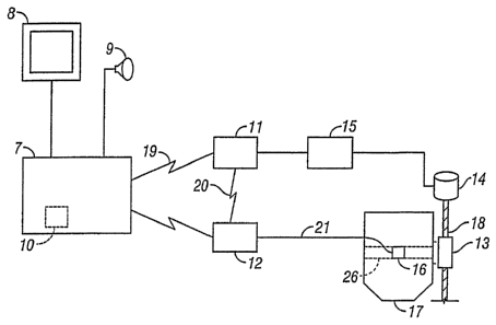
[0014] FIG. 1 depicts a schematic view of one embodiment of the closed-loop
focusing
system according to the present invention. A computer 7 having a CPU 10 on a
motherboard is
interconnected to a digital to analog converter card 11 by way of a cable 19.
The CPU 10 sends
instructions to the digital/analog converter card 11 thereby providing a
voltage from a power
source 15 to a motor 14. The motor provides linear movement of the movable
zoom lens
assembly 26 (shown in a housing 17) via a drive shaft 18 housed in a drive
shaft housing 13.
Alternatively, a mirror or series of mirrors may be used as the movable
element. A feedback
positioning device 12, such ~as a linear encoder, utilizing a sensor 16, reads
the movement of the
focusing assembly 26. The feedback positioning device 12 is interconnected
with the CPU 10. A
monitor or screen 8 and a speaker 9 may be utilized to provide audible and/or
visual warnings.
[0015] In one embodiment, the focusing assembly is part of a Z galvo motorized
focusing
system. A Z galvo is generally a limited excursion motor whose torque is
directly proportional
to the current applied. When current is applied to the motor, the galvo's
shaft rotates through
part of a circle. As long as the current is applied the shaft will remain
rotated in correlation to
the amount of current applied. When current is reduced, the shaft rotates
toward its original
position with the shaft returning to its resting position when current is
removed. Based on the
amount of current applied to the motor, the focal point of light through the
focusing assembly is
displaced. In another embodiment, the movable focusing assembly may be a
curved mirror or a
series of curved and/or flat mirrors whose position determines the laser focal
depth position.
[0016] In one embodiment, a linear encoder, such as the MicroE SystemsTM model
(M2100L30SS200) product may be utilized as a feedback positioning device 12.
The MicroE
CA 02563766 2006-10-19
WO 2005/106559 PCT/US2005/012008
Docket No.: HO-P02306US1
encoder product consists of an encoder strip (a glass strip with reflective
gradient), a sensor head
16, and interpolator to serial module 12. The encoder is preferably configured
for a resolution of
.1 p,m or less per count at a frequency of about 900 kHz or greater.
[0017] The CPU utilizes the linear encoder to accurately check the position of
the zoom
lens assembly and thereby control the focal position to within a few of
microns of an absolute
value. This is accomplished by knowing the galvo command voltage increments
(linear voltage
steps that produce linear galvo rotation). The galvo produces precise
rotational motion of the
lead screw that actuates the movement of the focusing assembly. An optical
encoder gradient
strip is attached to the focusing assembly. The encoder, therefore, accurately
measures the
movement of the focusing assembly. With knowledge of the encoder output (a
number of counts
per micron of movement) and the galvo voltage step command (the number of
voltage steps per
micron of movement) the system software can compare the two and determine if
the condition is
normal or out of range.
[0018] As further illustrated in Fig. 2a-2c, the sensor head 16 is affixed to
the housing 17
where a window or opening in the housing 17 exists so that the sensor head 16
can read a
"gradient strip 25 affixed to the focusing assembly 26. As the focusing
assembly 26 is moved or
moves in a linear fashion the sensor head 16 reads the movement of the
focusing assembly 26.
The focusing assembly as depicted in the Figures is used to focus a laser beam
22 to a fixed focal
point 23 in conjunction with other optical elements 27, 28 and 29.
[0019] A quadrature (A, B, and Index) to serial RS-232 converter, model #AD4-B-
D-
51767 from U.S. Digital, may be utilized as a digital/analog converter card
11. The AD4-B
board is preferably connected to a computer 7 motherboard via a nine pin cable
19 rnnning at a
standard 9600 baud.
[0020] The MicroE interpolator 12 and the U.S. Digital board 11 are mounted
together
as an assembly. Power is provided to the assembly via a DC plug that plugs
into the U.S. digital
board from the computer system power supply +12VDC. The interpolator and AD4-B
board are
connected via cable 20. The quadrature signals are passed to the U.S. Digital
board 11 from the
MicroE interpolator via RS-422 (differential). Also power is provided to the
MicroE board via a
power cable. The MicroE sensor head 16 is attached to the housing 17 via a
cable 21 from the
interpolator 12. The encoder glass strip 25 is attached to the focusing
assembly 26 with a UV
cured adhesive.
CA 02563766 2006-10-19
WO 2005/106559 PCT/US2005/012008
Docket No.: HO-P02306US1
[0021] The computer 7 controls positioning of the focusing assembly 26 and
receives
data pertaining to the position of the focusing lens assembly from the
interpolator 12.
[0022] Software Control of the Closed-loop Focal Positioning System
[0023] In one embodiment of the inventive system, the focal position is
computed and
controlled via software instructions preferably executable via a CPU 10. The
software
instructions may be contained on storage media such as CDs, hard drives,
diskettes, or other
electronic storage media devices. Additionally, the computer software
(instruction sets) may be
stored in ROM, RAM or other storage devices capable of storage computer
instructions. The
software program may be configured to provide various control of the focusing
assembly 26.
Functions performed by the software may include: Initialization of the System,
Calibration of the
System, Movement of the Focusing Assembly, Automatic Repositioning of the
Focusing
Assembly, and Determination that the Focusing Assembly is at a Desired
Position. Based on this
disclosure other functions would be readily ascertainable to one skilled in
the art.
[0024] Initialization of the System. An initialization and error checking
process is
performed to determine whether individual components of the system are
operable. A status or
response is requested from the component devices such the focusing assembly
(e.g., the Z galvo
objective lens), the analog-to-digital converter, linear encoder and the
communication ports.
Should any of these devices respond with an error code or not respond at all
then the software
will indicate such an error.
[0025] Calibration of the System. The software checks the linear encoder index
affixed
to the focusing assembly. In one embodiment, a Z galvo is commanded. to move
through its
upper and lower limits and a zero position is established. The Z galvo is then
parked or stopped
at a zero position. Additionally, the software calibrates the Z galvo by
submitting a signal to a
digital to analog converter, which in turn provides positive and negative
voltage signals to the Z
galvo. After the Z galvo is instructed to move a reading is taken from the
encoder index.
(0026] Movement of the Focusing Assembly. After calibration of the Z galvo,
positioning commands are made to move the Z galvo to the desired position.
Initially, the Z
galvo begins at a zero position. The Z galvo focusing assembly is commanded to
move to
desired positions. With the linear encoder, the actual position of the
focusing assembly is then
determined.
CA 02563766 2006-10-19
WO 2005/106559 PCT/US2005/012008
Docket No.: HO-P02306US 1
[0027] Determination that the Focusing Assembly is at a Desired Position. Once
the
Z galvo is moved to a desired position, the actual position of the Z galvo is
determined. An
encoder sensor reads the encoder index through a housing window.
[0028] The software program compares the actual focusing assembly position to
the
desired focal depth position. The software determines whether the desired
focal depth position is
within a certain range. If the actual focusing assembly position and the
desired focal depth
position are within range, then the software will allow the laser treatment of
the eye to continue.
If the actual focusing assembly position is out of range, then the software
will prevent laser
treatment from commencing.
[0029] An acceptable range may be configured according to the particular uses
of the
focusing system. In the context of ophthalmic surgery, the differences between
the desired
position and the actual position should be typically 5 microns or less. This
assures that the
positioning of the lens and subsequent treatment of the eye structure will be
extremely accurate.
For example, an acceptable range can be set as follows:
If the D <= X, where D is the difference between the desired position and
actual position,
X is 5 microns or less, then no lens adjustment is made and laser treatment is
allowed;
If the X < D < Y, where Y is 25 microns, then readjust the focusing assembly
to reduce
the difference between X and Y, and reconfirm proper X value; and
If D >= Y, then the focusing assembly needs to be recalibrated and no laser
treatment
should occur.
[0030] In the closed-loop focusing system of the present invention, movement
of the lens
may achieved in number of ways, including, but not limited to, the following:
[0031] 1. A computer processor may instruct a motorized focusing assembly to
linearly move the assembly to a desired position from a base position. The
processor
interconnected with a digital-to-analog converter provides a voltage source to
the motorized lens
thereby moving the lens to the desired position. A feedback positioning device
then determines
the actual position of the lens.
[0032] 2. Additionally, the computer processor may instruct movement of the
focusing assembly when the focusing assembly is not positioned at its base
position. For
example, the computer processor may have previously moved the focusing
assembly to a desired
position. The focusing assembly would be moved to the new position without
having to return to
CA 02563766 2006-10-19
WO 2005/106559 PCT/US2005/012008
Docket No.: HO-P02306US 1
the base position. The value of the current position and the new desired
position are used to
calculate how much the focusing assembly should be positioned.
[0033] 3. The focusing assembly may also be commanded to move by specific
increments by the operator of the system. For example, the assembly may be
commanded to
move up or down by specific increments, such as microns.
[0034] Automatic Repositioning of the Focusing Assembly. A delta value can be
computed as the absolute difference between the desired position value and the
actual position
value. The delta value can then be compared to an acceptable range of variance
between the
desired position and the actual position. If the delta value is slight, say
about plus or minus 2
microns, then the focusing assembly would not be repositioned. However, if a
greater delta
value exists, say between > 2 microns to < 25 microns, then the focusing
assembly would be
slightly repositioned so that the difference between the desired positioned
and actual position is
plus or minus 2 microns. If the variance is greater than 25 microns, than the
focusing assembly
should be recalibrated. The accuracy needed for repositioning the focusing
assembly would
depend on the particular application. The system may be configured such that
the repositioning
of the focusing assembly is completed at the end of each instructed movement.
Alternatively,
during the movement of the focusing assembly the feedback positioning device
can monitor an
actual position and compare it with the position where the system, estimates
the position of the
focusing assembly. In this manner, corrective action can be taken immediately
and the focusing
assembly repositioned real-time if the delta value falls outside of an
acceptable range.
[0035] Exemplary Implementation of the Closed-Loop Focal Positioning System
[0036] Referring to FIG. 4, a perspective view of an exemplary ophthalmic
laser system
in which the present inventive system may be implemented is shown. A user
interface and
terminal 31 provides for data input into a CPU (not shown) of desired focal
values. The
exemplary ophthalmic laser system includes an emergency shut off switch 32,
disk drive 33, key
switch 34, beam delivery device 35, operating microscope 36, control panel 37,
and a loading
deck for interface to an eye-stabilizing device.
[0037] Referring to FIG. 5, a schematic view of the exemplary ophthalinic
laser system
of FIG. 4 is shown. A laser source 41 is directed through a beam delivery
device into a z-
scanning objective lens 43. A display 42 is provided for viewing the eye
undergoing laser
treatment. The display may provide visual warning to the operator of the
system when the
focusing assembly falls outside of an acceptable range.
CA 02563766 2006-10-19
WO 2005/106559 PCT/US2005/012008
DocketNo.: HO-P02306US1
[0038] The inventive systems and methods described above are well adapted for
a
closed-loop focal positioning system. However, it shall be noted that the
foregoing description is
presented for purposes of illustration and description, and is not intended to
limit the invention to
the form disclosed herein. Consequently, variations and modifications to the
systems and
processes commensurate with the above teachings and teaching of the relevant
art are within the
scope of the invention. For example, as mentioned previously, several aspects
of the invention
may be adapted for application or implementation onto an interactive computer
network or
client-server system other than the Internet. These variations will readily
suggest themselves to
those skilled in the relevant art and are encompassed within the spirit of the
invention and the
scope of the following claims.
[0039)' Moreover, the embodiments described are fzu-ther intended to explain
the best
modes for practicing the invention, and to enable others skilled in the art to
utilize the invention
in such, or other, embodiments and with various modifications required by the
particular
applications or uses of the present invention. It is intended that the
appending claims be
construed to included alternative embodiments to the extent that it is
permitted by the prior art.