Note: Descriptions are shown in the official language in which they were submitted.
CA 02564184 2006-10-24
WO 2005/109326 PCT/US2005/015232
ANTI-SKIMMING CARD READER SURFACE
CONFIGURATION
1. Field of the Invention
[0001] This invention generally relates to card reader security. More
particularly, this invention relates to preventing placing a skimming reader
over a
card reader.
2. Background of the Invention
[0002] Automated teller machines (ATMs) have become well known and
widely used. ATMs allow individuals twenty-four hour access to their bank
accounts to conduct a number of transactions. One advantage to ATMs is their
convenience to bank customers. Another advantage is the ability for banks to
have
transactions automated, which presents a cost savings to the bank.
[0003] One feature of ATMs is that they require a sufficient amount of
information regarding a bank customer before allowing a transaction to be
completed. The conventional way of providing such information to the ATM is by
inserting a card that includes a magnetic strip containing customer
information.
Following that, the customer enters a personal identification number and gains
access to their account(s). Some buildings include a vestibule housing the
ATM.
When the bank is closed, the vestibule is locked. A customer can temporarily
unlock the door by inserting their ATM card in a reader near the door to the
vestibule.
[0004] Maintaining customer account and access information
confidential and secure has recently become problematic. Skimming readers have
1
CA 02564184 2006-10-24
WO 2005/109326 PCT/US2005/015232
been developed that are placed over a card reader slot on an ATM or the card
reader
for entering the vestibule. These skimming readers read the magnetic strip on
the
card as a bank customer inserts their card for purposes of conducting a
transaction
with the bank. The skimming reader scans the magnetic strips and gathers the
information regarding each individual and their account.
[0005] By using a hidden camera or a secretly located individual, the
customer's access code (i.e., a manually entered PIN) can be gathered. That
information combined with the information gathered by the skimming reader
allows
an unauthorized individual to gain unauthorized access to the individual's
bank
account or accounts and make illegal fund withdrawals.
[0006] There is a need for protecting against someone placing a
skimming reader over the card reader associated with the ATM or the vestibule
entry. This invention addresses that need.
SUMMARY OF THE INVENTION
[0007] This invention provides a card reader configuration that reduces
or eliminates the possibility for someone to place a skimming reader over the
card
reader in a successful manner. With a disclosed example, even if a skimming
reader
is successfully placed over the card reader, the presence of the skimming
reader will
be readily visible apparent or it will interfere with the ability for the card
reader to
operate properly. Under either scenario, the skimming reader will be
detectible,
which prevents unauthorized access to personal information.
[0008] An exemplary disclosed card reading device includes a housing
having a slot for receiving the card and an asymmetric exterior surface near
the slot
2
CA 02564184 2006-10-24
WO 2005/109326 PCT/US2005/015232
that includes a plurality of distinct surface portions aligned at oblique
angles to each
other.
[0009] In one example, the plurality of distinct surface portions are
aligned at at least three different oblique angles relative to each other. In
one
example, each distinct surface portion is at least partially flat.
[0010] One disclosed example includes a notch in the housing that has a
depth beyond a reference plane and a dimension for receiving at least a
portion of a
finger. The slot in this example is at least partially within the housing for
receiving
a card and has a first portion aligned with the notch and a second por-tion
adjacent to
the notch. With this example, when a card is inserted within the slot, some of
the
card is covered by the second portion of the slot and another portion of the
card is
aligned with the first portion of the slot and the notch such that it is
accessible from
outside of the housing. The configuration of the notch in one example
effectively
prevents a skimming reader from being unnoticeably positioned near a reader
portion of the device.
[0011] The various features and advantages of this invention will become
apparent to those skilled in the art from the following detailed description.
The
drawings that accompany the detailed description can be briefly described as
follows.
BRIEF DESCRIPTION OF THE DRAWINGS
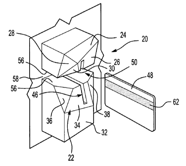
[0012] Figure 1 schematically shows an example card reader housing
designed according to one embodiment of this invention.
3
CA 02564184 2006-10-24
WO 2005/109326 PCT/US2005/015232
[0013] Figures 2A and 2B schematically show an example feature of the
exterior surface configuration of the card reader housing of Figure 1.
[0014] Figure 3 schematically shows a feature of a slot in the example
housing.
[0015] Figure 4 schematically shows an operational feature of an
example housing configuration.
[0016] Figure 5 schematically shows the feature of Figure 4 with a card
in a fully inserted position.
DETAILED DESCRIPTION
[0017] Figure 1 schematically shows a portion of a card reader housing
having an exterior surface configuration 22 that is designed in a unique
manner to
15 prevent the placement of a skimming reader over the top of the card reader
housing
20. The example exterior surface configuration 22 is non-continuous and
asymmetric. The illustrated example surface configuration 22 is non-continuous
because it includes various portions at different angles with visible
transition points
between the various portions. In other words, the non-continuous surface
20 configuration 22 includes a plurality of distinct surface portions. The
illustrated
example is asymmetric because there is an unbalanced distribution and
alignment of
the various por-tions across the surface configuration. The right half is not
a mirror
image of the left half, for example.
[0018] The example configuration includes a plurality of at least partially
flat surface portions 24, 26, 28, 30, 32, 34, 36 and 38, at various oblique
angles
4
CA 02564184 2006-10-24
WO 2005/109326 PCT/US2005/015232
relative to each other. Having the plurality of surface portions 24-38 at
various,
different angles makes it difficult, if not impossible, for a skimming reader
to be
designed to readily fit over the card reader housing 20 in a manner that it
cannot be
easily detected. In some examples, any attempt to place a skimming reader on
top of
the card reader housing 20 will fail absent significant efforts or techniques.
Further,
any appended skimming reader likely will be easily detected by someone
attempting
to properly use the card reader after the skimming reader is in place.
[0019] As can best be appreciated from Figures 2 and 3, various surface
angles can be used at various portions of the exterior surface configuration
22. In
the illustrated example, the surface portion 26 is aligned transverse to the
surface
portion 28. Having an intentionally non-continuous and asymmetric surface
configuration 22 is enough to prevent someone from attaching a skimming reader
in
most situations.
[0020] Figures 2A and 2B schematically show geometric relationships
between selected portions of the exterior configuration 22. Figures 2A and 2B
show
the angular relationships between the surface portions 26 and 28. As can be
appreciated from Figure 2A, the surface portion 28 is at an oblique angle
relative to
the surface portion 26. As can be appreciated from Figure 2B, a plane 28'
parallel to
the surface portion 28 is at an oblique angle relative to a reference plane
40. A plane
26' parallel to the surface portion 26 is also oriented at an oblique angle
relative to
the reference plane 40. The respective angles of the planes 26 and 28 relative
to the
reference plane 40 are different.
[0021] Additionally, the orientation of the planes 26' and 28' relative to
the reference plane 40 are different. The plane 26', for example, effectively
5
CA 02564184 2006-10-24
WO 2005/109326 PCT/US2005/015232
intersects the reference plane 40 along a line 42, which is generally
horizontal in the
illustration. The plane 28' intersects the reference plane 40 along a line 44,
which is
generally vertical in the illustration. The lines 42 and 44 are arranged
transverse to
each other. In one example, the lines 42 and 44 are perpendicular to each
other.
[0022] Figure 2B schematically shows how various surface portions of
the exterior configuration 22 can be arranged at a variety of different angles
to
provide an asymmetric or non-continuous exterior surface configuration 22,
which
does not lend itself to a skimming reader being secured over top of the
housing. A
relatively complicated exterior configuration 22 would require an individual
to
expend substantial effort to design a skimming reader that would be able to
fit over
the exterior configuration 22 in a manner that would not be readily, visually
apparent.
[0023] As can be appreciated from Figures 1 and 3, the example housing
includes a slot 46 for receiving a card 48 such as an ATM banking card.
Another
15 feature of the example embodiment is that a finger-receiving notch 50 is
associated
with the card slot 46. The card slot 46 in this example includes a first
portion 52 and
a second portion 54. The first portion 52 of the card slot 46 is directly
aligned with
the finger-receiving notch 50 and the second portion 54 is adjacent to the
finger-
receiving notch 40.
20 [0024] The notch 50 in this example has a dimension corresponding to
an average width of an individual's finger. As best appreciated from Figures 3
and
4, two surfaces 56 are spaced apart to define a width of the notch (which
extends in
a vertical direction in the drawings). Another surface 58 defines a depth of
the notch
from a reference plane 59 associated with the exterior configuration 22 of the
6
CA 02564184 2006-10-24
WO 2005/109326 PCT/US2005/015232
housing 20. The reference plane 59 is positioned perpendicular-to the card 48
when
the card is received within the card slot 46. The finger-receiving notch 50
includes a
width dimension that generally corresponds to an average finger width.
[0025] Referring to Figure 4, an electronic reader 60 according to one
example is disposed within the card reader housing 20. The electronic reader
60 is
aligned with the notch 50. The electronic reader 60 reads a magnetic strip 62
on the
card 48 in a known manner. The reader 60 detects a partial read resulting from
a
partial insertion of the card 48 into the slot 46 in a known manner.
[0026] In the illustrated example as shown in Figures 4 and 5, full
insertion of the card 48 is achieved when a trailing edge 64 of the card 48
passes the
reference plane 59 a sufficient distance for the reader 60 to obtain a full or
complete
read of the strip 62. At least a portion of a finger 70 must be received
within the
finger-receiving notch 50 for this to occur.
[0027] In this example, the dimension of the notch 50 (and particularly
the spacing between the surfaces 56) is arranged to allow the average human
finger
70 to fit within the notch 50 during card insertion. If an individual
attempted to
attach a skimming reader to the housing 20 in a manner that would reduce the
spacing between the surfaces 56, the typical finger would not'be able to be
received
within the notch and the card 48 could not be fully inserted into the slot 46.
Under
these circumstances, the reader 60 will detect a partial read. In some
examples, the
reader 60 provides an alert indication whenever a number of partial reads
exceeding
a selected threshold occurs within a selected period of time. A number of
partial
reads, for example, may provide an indication that some alteration to the
housing 20
has been made, which may provide an early alert that a skimming reader has
been
7
CA 02564184 2006-10-24
WO 2005/109326 PCT/US2005/015232
attached to the housing 20. By restricting the dimensions of the notch 50, the
illustrated example make it even more difficult for the attachment of a
skimming
reader.
[0028] It is not possible to fully insert the card 48 without having
unhindered access to the slot 50 because some of the card 48 is completely
covered
by the second portion 54 of the slot 46 when the card is fully inserted as
shown in
Figure 5, for example. Another portion of the card 48 is accessible within the
notch
50 from outside of the housing 20. Only the latter portion of the card is
accessible
when the card 48 is fully inserted in the slot 46 to achieve a complete read
by the
reader 60. Accordingly, any modification to the slot 50 will hinder an
individual's
ability to properly insert their card into the slot 46.
[0029] As can be appreciated from Figures 4 and 5, the strategic
alignment of the finger-receiving notch 50 and the electronic reader 60
further
prevents the attachment of a skimming reader because any increased surface
thickness in the area of the surface 58 that would be introduced if a skimming
reader
were attached on or in front of the surface 58 will prevent full insertion of
the card
48. Any reduction in the depth of the notch 50 will prevent a complete card
read.
Alternatively, an individual will not be able to retrieve their card because
not enough
of the card 48 will remain accessible in the notch 50 upon full insertion.
[0030] Strategically positioning and sizing the notch 50 provides
enhanced safety in this example. An individual who attempts to gain access to
a
vestibule, for example, will not be able to fully insert their card because of
the
presence of a skimming reader that reduces any dimension of the notch 50.
Failure
to achieve full insertion of the card 48 results in the inability of the
electronic reader
8
CA 02564184 2006-10-24
WO 2005/109326 PCT/US2005/015232
60 to properly read the card 48. When the individual is not able to gain
access to
that vestibule, that provides an indication that something is wrong. After
several
customer complaints, for example, the bank will be prompted to check the card
reader housing 20 and could at that time discover the presence of the skimming
reader.
[0031] Moreover, if one does not gain access to the vestibule, they will
not enter their personal identification number (PIN) into the ATM and,
therefore, the
potential thief who has placed a skimming reader on the vestibule entry card
reader,
which may obtain its own full read even if the reader 60 does not, will not be
able to
gain access to the PIN number and will not be able to use any card information
extracted by the skimming reader.
[0032] The illustrated example includes various features that provide
enhanced safety and security for preventing unauthorized capturing of personal
or
banking information using a skimming reader, for example. The illustrated
example
includes a combination of security features. Any one of these, all of them or
a sub-
combination of them may provide sufficient security for a given situation.
Those
skilled in the art who have the benefit of this description will be able to
select from
an asymmetric surface configuration, a non-continuous surface configuration, a
strategically dimensioned and positioned notch or a combination of these
features to
meet the needs of their particular situation.
[0033] The preceding description is exemplary rather than limiting in
nature. Variations and modifications to the disclosed examples may become
apparent to those skilled in the art that do not necessarily depart from the
essence of
9
CA 02564184 2006-10-24
WO 2005/109326 PCT/US2005/015232
this invention. The scope of legal protection given to this invention can only
be
determined by studying the following claims.