Note: Descriptions are shown in the official language in which they were submitted.
CA 02564408 2012-03-16
Nano-Crystalline Steel Sheet
Field of Invention
The present invention relates generally to metallic glasses, and more
particularly
to a metallic glass sheet material and methods for forming the same.
Specifically, a
method of producing a metallic glass sheet is disclosed in which a molten
metallic glass
forming alloy is formed into a sheet material.
Background
It has been known for at least 30 years, since the discovery of Metglasses
(iron
based glass forming compositions used for transformer core applications) that
iron based
alloys could be made to be metallic glasses. However, with few exceptions,
these iron
based glassy alloys have had very poor glass forming ability and the amorphous
state
could only be produced at very high cooling rates (> 106 K/s). Thus, these
alloys may
only be processed by techniques which give very rapid cooling such as drop
impact or
melt-spinning techniques.
While conventional steels have critical cooling rates for forming metallic
glasses
in the range of 109 K/s, special iron based metallic glass forming alloys have
been
developed having a critical cooling rate orders of magnitude lower than
conventional
1
CA 02564408 2006-10-26
WO 2005/118902 PCT/US2005/014423
steels. Some special alloys have been developed that may produce metallic
glasses at
cooling rates in the range of 104 to 105 K/s. Furthermore, some bulk glass
forming alloys
have critical cooling rates in the range of 10 to 102 K/s, however these
alloys may
employ rare or toxic alloying elements to increase glass forming ability, such
as the
addition of beryllium, which is highly toxic, or gallium, which is expensive.
The
development of glass forming alloys which are low cost and environmentally
friendly has
proven much more difficult.
In addition to the difficultly in developing cost effective and
environmentally
friendly alloys, the very high cooling rate required to produce metallic glass
has limited
the manufacturing techniques that are available for producing articles from
metallic glass.
The limited manufacturing techniques available have in turn limited the
products that
may be formed from metallic glasses, and the applications in which metal
glasses may be
used. Conventional techniques for processing steels from a molten state
generally
provide cooling rates on the order of 10-2 to 10 K/s. Special alloys that are
more
susceptible to forming metallic glasses, i.e., having reduced critical cooling
rates on the
order of 104 to 105 K/s, may not be processed using conventional techniques
with such
slow cooling rates and still produce metallic glasses. Even bulk glass forming
alloys
having critical cooling rates in the range of 100 to 102 K/s, are limited in
the available
processing techniques, and have the additional processing disadvantage in that
they
generally may not be processed in air but only under very high vacuum.
Common processing techniques used with metal glasses generally involve thermal
spray coating. In a thermal spray coating process an atomized spray of molten
metal may
cool to a solid very quickly, exhibiting cooling rates in the range of 104 to
105 K/s. This
2
CA 02564408 2012-03-16
rapid initial cooling facilitates the formation of a metallic glass structure.
However, even
while thermal spray coating may achieve a cooling rate sufficient to form
metallic glass
coatings, the rate of application of the coatings, as well as the coating
thickness, may be
limited by the need for secondary cooling of the solidified deposit down to
room
temperature. Secondary cooling may occur at much slower rate, typically in the
range of
50 to 200 K/s. If a coating is too thick or the coating is built up too
quickly, the thermal
mass of the coating may cause devitrification, and the metallic glass coating
may begin to
crystallize.
Three methods that have been examined for producing an amorphous, or metallic
glass, steel sheet or plate are spray forming, spray rolling, and planar flow
casting
followed by consolidation. Spray forming, such as spray casting, including the
so-called
OspreyTM process, involves depositing atomized liquid metal onto a substrate
which collects
and solidifies the droplets of the liquid metal. This method may be analogized
to
producing a thick cross-section by thermal spray coating.
Spray rolling is a method that is somewhat related to spray casting. Spray
forming or casting may generally involve depositing atomized liquid metal on a
substrate
having a shape corresponding to the desired shape of the cast article. In the
process of
spray rolling, rather than spraying an atomized liquid metal onto a substrate,
the atomized
liquid metal may be sprayed onto two rollers. The rollers may compress the
sprayed
droplets to reduce the porosity of the accumulated droplets. Spray rolling
may, therefore,
produce a less porous and denser sheet than spray casting.
The third common method for producing sheets of steel metallic glass is planar
flow cast ribbon consolidation. According to this method, thin ribbons of
metallic glass
3
CA 02564408 2012-03-16
may be produced using a planar flow method. Several thin ribbons may be
stacked on
top of one another to achieve a desired sheet or plate thickness. While the
stacked metal
ribbons are still in a heated condition they may be consolidated into a single
sheet or plate
by warm rolling. This process has generally been applied to minimize eddy
current
losses in amorphous transformer core alloys and has not been examined as a
route to
develop mechanical properties.
Summary
According to one aspect, the present invention provides a process for
selecting a
metal alloy suitable for forming a nano-crystalline steel sheet. The process
may include
the use of two casting rolls, the rolls having a gap therebetween, and
supplying a liquid
metallic glass forming alloy to the casting rolls proximate to the gap. The
process may
further include forming a sheet by rotating the casting rolls in opposite
directions and
cooling the liquid metallic glass forming alloy to produce a nano-crystalline
microstructure.
According to another aspect, the present invention provides a sheet including
an
iron based alloy present as a continuous structure across a thickness of the
sheet, wherein
the sheet has a crystalline grain size less than about 100 microns.
According to another aspect, the present invention is directed at selecting a
metallic glass forming alloy having a critical cooling rate, viscosity,
oxidation resistance,
and relatively low melt reactivity suitable for processing into a nano-
crystalline steel
sheet, via strip casting methodology.
According to another aspect, the nano-crystalline steel sheet has a hardness
in the range of about 940 km/mm2 to 2500 kg/mm2.
4
CA 02564408 2006-10-26
WO 2005/118902 PCT/US2005/014423
Brief Description of the Drawings
Features and advantages of the present invention are set forth herein by
description of embodiments consistent with the present invention, which
description
should be considered in conjunction with the accompanying drawings, wherein:
FIG. 1 is a schematic drawing of an apparatus that may be used to form nano-
crystalline steel sheet consistent with the present invention; and
FIG. 2 is an enlarged schematic view of the intersection of the rolls for the
apparatus shown in FIG. 1.
Detailed Description of Preferred Embodiments
The present invention is directed at the formation of a nano-crystalline steel
sheet
material and a method for producing the same. As used in any embodiment herein
the
terms metallic glass, nano-crystalline and amorphous metallic material all
generally refer
to a metallic material having a microstructure with a crystalline grain less
than about 200
microns, preferably with a crystalline grain size less than about 100 microns,
and more
preferably with a crystalline grain size less than about 1 micron.
Consistent with the present invention, the nano-crystalline materials may be
iron
based alloys, such as those marketed under the name Superhard Steel AlloysTM,
available
from The NanosteelTM Company as well as a derivative of such a metallic glass-
forming,
iron alloy. It will be appreciated that the present invention may suitably
employ other
alloys based on iron, or other metals, that are susceptible to forming
metallic glass
materials at critical cooling rates less than about 105 K/s. Accordingly, an
exemplary
alloy may include a steel composition, comprising at least 50% iron and at
least one
5
CA 02564408 2006-10-26
WO 2005/118902 PCT/US2005/014423
element selected from the group consisting of Ti, Zr, Hf, V, Nb, Ta, Cr, Mo,
W, Al, and
the class of elements called rare earths including Y, Sc, La, Ce, Pr, Nd, Sm,
Eu, Gd, Tb,
Dy, Ho, Er, Tm, Yb and Lu; and at least one element selected from the group
consisting
of B, C, N, 0, P and S. In such regard, alloys of the present invention
comprise up to
about 15 elements, and all numerical permutations of alloys therebetween
(e.g., alloys of
up to about 14 elements, up to about 13 elements, or alloys between 4-15
elements, 5-14
elements, etc.).
Along such lines, it should be appreciated that the above reference to the
preferred
number of alloy forming elements clearly establishes that the presence of
additional
elements that do not form or contribute to the alloy forming materials herein,
while
tolerable and anticipated, do not depart from the basic character of this
invention. In
other words, the invention herein recognizes that the presence of other
elements in
concentrations at or below about 1% wt (10,000 ppm) would not be considered to
be part
of the principal alloys of the present invention, which as noted, may comprise
up to about
15 or fewer elements.
In addition, it is worth noting that in particular preferred embodiment, the
alloys
of the present invention may comprise four to six elements in their
compositions. Among
such elements are iron, chromium (which can be included for corrosion
resistance),
boron, carbon, and/or phosphorous which can be included to lower the melting
point and
aid glass formation. Accordingly, the particular temperature for devitrifying
the metal
glass may be varied depending upon the particular alloy used, and a particular
processing
method for forming the steel sheet. Furthermore, one or both of molybdenum and
6
CA 02564408 2006-10-26
WO 2005/118902 PCT/US2005/014423
tungsten can be included to control hardness and improve corrosion resistance
in specific
environments.
Consistent with the present invention, a nano-crystalline steel sheet may be
formed using a two-roll casting process. The two roll process herein may allow
nano-
crystalline steel to be formed as a smooth, continuous ribbon having a desired
thickness.
The two roll process may produce sheets having a thickness in the range of
about 0.4 to
mm, and therefore may not require subsequent rolling to produce sheet. The
nano-
crystalline steel sheet produced according to the present invention may
subsequently be
processed using conventional sheet processing techniques that do not heat the
sheet above
10 the crystallization temperature.
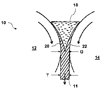
Turning to FIGS. 1 and 2, an exemplary system 10 for producing a nano-
crystalline steel sheet 11 consistent with the present invention is shown. The
apparatus
10 may generally include two counter-rotating rolls 12, 14. The counter-
rotating rolls
may be separated by a gap G that may generally correspond to the desired
thickness T of
the sheet 11. It should be recognized that, while controlling the gap G may be
used to
control the thickness T of the sheet 11, the gap G between the rolls 12, 14
may not
necessarily be the same as the thickness T of the sheet 11. The apparatus 10
may also
include a nozzle 16, or other delivery device, for supplying molten, or
liquid, nano-
crystalline forming alloy to the counter-rotating rolls 12, 14.
The molten alloy may be allowed to accumulate between the casting rolls 12,
14,
thereby forming a bead or puddle of the liquid alloy 18. A partially
solidified layer of the
alloy 20, 22 may form on the respective casting rolls 12, 14. As the two
casting rolls 12,
14 rotate the layers of alloy 20, 22 formed on each casting roll 12, 14 may be
pressed
7
CA 02564408 2006-10-26
WO 2005/118902 PCT/US2005/014423
together and passed through the gap G between the rolls. Pressing the
partially solidified
layers 20, 22 between the casting rolls 12, 14 may cause the partially
solidified layers to
merge together and may produce a single sheet 11 of nano-crystalline steel.
The accumulation of alloy between the casting rolls 12, 14, i.e. the size of
the
bead 18, may be controlled to ensure that an adequate quantity of alloy is
present between
the casting rolls 12, 14 to allow the continual formation of the nano-
crystalline sheet 11.
The size of the bead 18 may influence the formation and thickness of the
partially
solidified layers 20, 22 of the alloy formed on each of the casting rolls 12,
14. For
example, the bead 18 may provide a sufficient thermal mass to influence the
rate of
cooling of the partially solidified layers 20, 22. The size of the bead 18
may, therefore,
be varied to control the thickness and degree of solidification of the
partially solidified
layers 20, 22. The thickness and degree of solidification of the partially
solidified layers
may also be influenced by throughput of the casting rolls 12, 14, rotational
speed of the
casting rolls 12, 14, and by the location of the liquid alloy as it is
directed by the nozzle
16.
Consistent with the present invention, the cooling rate of the alloy from a
liquid to
a solid may be on the order of 104 K/s. According to one specific embodiment,
the
cooling rate of the alloy during solidification may be approximately 12,000
K/s.
Accordingly, the alloy may solidify before significant growth of crystalline
domains,
thereby producing a nano-crystalline microstructure.
The exact cooling rate during solidification may be influenced by a number of
factors, such as rate of rotation of the casting rolls 12, 14, the material
from which the
casting rolls 12, 14 are formed, the use of additional cooling, etc. In one
embodiment,
8
CA 02564408 2006-10-26
WO 2005/118902 PCT/US2005/014423
the twin casting rolls 12, 14 may be provided. In another embodiment, the twin
casting
rolls may be formed from a copper alloy material. Copper alloy may provide a
relatively
high thermal conductivity and may increase the cooling rate of the steel sheet
being
formed. The cooling rate provided by copper alloy casting rolls 12, 14 may be
sufficient
to solidify the alloy in a nano-crystalline or glass state. It should be
understood, however,
that suitable casting rolls may be formed from materials other than a copper
alloy, and
still provide a sufficient cooling rate.
Additional cooling may be provided either by chilling the casting rolls 12, 14
or
by providing a cooling medium on the exit side of the casting rolls 12, 14.
For example,
a cooling spray of water etc. may be applied to the sheet 11 as it exits the
gap G between
the casting rolls 12, 14. It should be noted that the present method may
provide a high
cooling rate during solidification, which is one critical cooling time.
However, once the
strip has solidified and passed from the casting rolls 12, 14, the cooling
rate may slow
greatly, for example to on the order of about 1700 C/s. However, this lower
cooling rate
is post solidification, that is, after the microstructure of the nano-
crystalline steel sheet
may generally be fixed. Optionally, additional cooling may be provided after
the sheet
11 has passed from the casting rolls 12, 14 to increase the post
solidification cooling rate.
For example, a cooling bath or water mist cooling, etc. may be employed to
increase the
cooling rate.
The lower cooling rate observed after the sheet 11 has solidified may actually
be
beneficial in some instances. For example, the lower cooling rate may enhance
the
malleability of the sheet 11, making it more susceptible to secondary forming
or
9
CA 02564408 2006-10-26
WO 2005/118902 PCT/US2005/014423
processing operations. In this regard,, the sheet 11 may undergo a secondary
rolling
process to further reduce, or control, the thickness of the sheet.
Nano-crystalline steel alloys suitable for use with the present invention, may
exhibit a variety of physical and/or mechanical characteristics that may
facilitate sheet
forming consistent with the present invention. For example, nano-crystalline
forming
steel alloys may have a low melt viscosity, as compared with conventional
steel alloys.
While conventional metal alloys exhibit liquid viscosities in the melt in the
range of 1.5
to 5 mPa-s, glass forming iron based alloys herein may generally exhibit a
liquid
viscosity range below about 1.5 mPa-s. A comparatively low melt viscosity may
allow
the nano-crystalline steel to be pressed into a thin sheet at a lower applied
force from the
twin casting rolls. Accordingly, thin sheets of nano-crystalline steel may be
formed
consistent with the present invention. A lower melt viscosity may also
facilitate
supplying the nano-crystalline alloy to the twin casting rolls and
distributing the alloy
between the rolls and across the width of the rolls.
In addition to the relatively low melt viscosity, nano-crystalline steel
alloys may
have a melting temperature that is lower than some conventional steel alloys,
i.e., from
approximately 950 C to 1350 C including all increments therebetween. The lower
melting temperature of some suitable nano-crystalline alloys may simplify the
production
of nano-crystalline steel sheet. The lower temperature may make the nano-
crystalline
steel alloy less expensive to process, and may make the alloy easier to handle
because of
the lower temperature of the melt.
A nano-crystalline steel sheet according to the present invention may have a
generally continuous structure across the thickness of the sheet. That is, the
sheet herein
CA 02564408 2006-10-26
WO 2005/118902 PCT/US2005/014423
is not an aggregation of discrete particles or layers. Desirably, the nano-
crystalline steel
sheet may generally have a crystalline grain less than about 100 microns, and
more
preferably a crystalline grain size less than about 1 micron.
The metallic glass sheet material according to the present invention may
provide
high tensile strength relative to conventional sheet steel materials. In
exemplary
embodiments, the tensile strength of the nano-crystalline steel sheet may be
in the range
of between about 250 ksi (1.72 GPa) and 1000 ksi (6.89 GPa). It is noted that
the upper
range of tensile strengths achievable by nano-crystalline steel sheets may be
higher than
KevlarTM (i.e. tensile strength on the order of 3.5 GPa). While nano-
crystalline steel
sheet herein may exhibit a higher tensile strength than KevlarTM, KevlarTM
exhibits a
higher specific strength (tensile strength/density) due to its low density
(1.44 g/cm3).
In addition to the very high tensile strength, nano-crystalline steel sheet
exhibits
exceptional strength to weight ratios as compared to conventional metal
alloys. A
comparison of strength to weight ratios for several conventional metallic
materials is
presented in Table 1.
Table 1. Strength To Weight Ratio of conventional alloys.
Strength to Weight
Density Tensile Strength Ratio
Material (g/cm3) (GPa) (cm)
1005 Steel 7.87 0.365 472,931
Titanium 4.50 0.220 498,528
316L stainless
Steel 8.03 0.485 615,893
11
CA 02564408 2012-03-16
304 Stainless Steel 7.90 0.572 738,326
4340 Steel 7.85 0.745 967,756
NickelvacT"" C-22 8.02 0.793 1,008,273
HaynesTM 25 Cobalt 9.13 0.930 1,038,703
Haynes 625 Nickel 8.44 0.905 1,093,416
StelliteTM 6 8.20 0.911 1,132,880
Magnesium 1.74 0.196 1,148,646
Al 6061-T6 2.70 0.31 1,170, 785
Al 7075-T6 2.81 0.572 2,075,721
W2 Tool Steel 7.83 1.630 2,122,781
Mg AZ80Z-T5 1.80 0.380 2,152,734
Ti-6-AI-4V 4.43 0.95 2,186,750
A6 Tool Steel 8.03 2.380 3,022,322
In Table 2, the measured strength to weigh ratios are shown for four (4)
alloys
consistent with the present invention; XPD 18, XPD 19, XPCAT, and XP7170. The
4
exemplary alloys are offered to aid in understanding the present invention and
are not to
be construed as limiting the scope thereof.
Note that the density was measured using the Archimedes Method with an
applicable density balance and the tensile strength was measured on
appropriately sized
tensile specimens. For the XPCAT alloy, the tensile strength was not measured
but
estimated based on the hardness (i.e. a3, = Hv/3).
Table 2 Properties of NanoSteel Alloys
Property XPD18 XPD19 XPCAT XP7170
Stoichiometery Few.2Crys.1W2.o FeM.SCrIe.2W2.0 Fe43.6Mn1.9Cr173Mo2.3
Fe52.3Mn2Cri9Mo2.s
(atomic %) B17.oC2.o B17.o
W1.6NI4.OB14.9C6.7sh.3 Wi.7Bi6.0C4.osi2.5
Density 7.70 7.70 7.65 7.59
12
CA 02564408 2006-10-26
WO 2005/118902 PCT/US2005/014423
(g/cm3)
Tensile 3.16 4.90
Strength 4.00 6.12a
(GPa)
Glass Hardness 1124 1052 --- 1299
k mm2)
Nanocomposite 1653 1565 1872` 1670
Hardnessb
(kg/mm2)
Strength to 5,297,227 4,184,809 8,157,730 6,583,148
Weight Ratio
(cm)
Peak Glass 545 538 620 631
Crystallization
Temperature
( C)
Melting Point 1160 1225 1134 1170
( C)
As-Crystallized 75 --- --- 25
Grain Size
average (nm)
[a] Note tensile strength for this sample estimated from the hardness
[b] Note hardness after heat treatment at 700 C for 1 hr
[c] Note hardness after heat treatment at 750 C for 1 hr
The testing results of the 4 exemplary alloys demonstrate that high tensile
strengths were obtained between about 3.16 to 6.12 GPa. Additionally, high
hardness
was obtained between about 1052 kg/mm2 and 1872 kg/mm2, depending on the alloy
composition and the structure that is obtained (i.e. glass or nanocomposite).
The strength
to weigh ratio of the alloys was found to be up to 3.7 times greater than the
archetypical
Ti6A14V aerospace alloy. Additionally, the nano-crystalline steel sheet
material
according to the present invention was superior for high strength to weight
ratio
applications in sheet form.
Furthermore, the melting point of the alloys studied was found to be much
lower
than conventional steels and varied from about 1160 C to 1225 C. The peak
crystallization temperature for the primary glass to crystallization
transition was found to
vary between 538 C to 631 C. The as-crystallized grain size was found from
direct TEM
13
CA 02564408 2012-03-16
observation to vary from 25 to 75 nm after a short heat treatment above the
crystallization
temperature.
The foregoing description is provided to illustrate and explain the present
invention. The scope of the
claims should not be limited by the preferred embodiments set forth in the
examples, but should be
given the broadest interpretation consistent with the description as a whole.
14