Note: Descriptions are shown in the official language in which they were submitted.
CA 02564631 2006-09-11
WO 2005/095027 PCT/FI2005/000138
1
CASTING TROUGH AND METHOD FOR CASTING COPPER ANODES
The invention relates to a method and arrangement for pouring molten material,
such as molten metal, into a casting mold. More precisely, the invention
relates
to a method and equipment for casting anodes used in electrolytic refining.
Controlled pouring and precise feeding in the casting mold is essential for
example in connection with the casting of metal anodes. In the production of
metals, the next process step after the casting of metal anodes is
electrolytic
refining, where a prerequisite for achieving a high cathode quality and high
efficiency is, among others, a homogeneous quality of the anodes with respect
to both shape and weight. In most known methods, anodes are cast in open
molds.
In the casting of anodes, such as copper anodes, the melt is conducted from
the anode furnace for example along a chute to the intermediate trough of the
casting equipment, from where the molten metal is further poured to the
casting
trough. The volume of the intermediate trough is remarkably larger than the
volume of the casting trough proper, and it also serves as a balancing
intermediate storage between the anode furnace and the casting trough. The
quantity of metal contained in the casting trough at the beginning of the
pouring
step is somewhat larger than the quantity of metal to be administered in the
casting mold in each batch. Usually the quantity of metal to be poured to in
the
casting trough is about double the quantity to be poured in the casting mold.
From the casting trough, molten metal is precisely administered in the open
casting mold. The casting trough is never completely emptied, but a so-called
copper base is left on the bottom. Modern anode casting is realized as an
automated process in so-called casting tables, where the casting molds are
shifted on a round casting table to the front of the casting trough. When
pouring
from the casting trough, the feeding is controlled by means of monitoring the
trajectory and motional speed of the casting trough as well as its weight.
Typically the quantity of melt to be poured into the casting mold of a copper
CA 02564631 2006-09-11
WO 2005/095027 PCT/FI2005/000138
2
anode is administered at the accuracy of 3 percentages. Usually the anode
weight is within the range 300 - 600 kilograms.
For accurately controlling the feeding of the quantity of melt to be poured,
the
casting trough is provided with weight sensors. The pouring is controlled
automatically, and it begins when the casting trough is filled with melt, the
initial
weight of the trough is measured, and the casting mold is placed in front of
the
casting trough. In the pouring process, the casting trough is tilted so that
the
molten metal flows over the casting trough spout to the casting mold. The
pouring is arranged to be stopped, when the weight of the casting trough is
reduced for the amount of the target weigh of the anode to be cast. Then the
casting trough is returned to its initial position to be refilled.
During one anode casting process, usually several hundreds of anodes are cast
in succession. At the end of the casting process, the casting trough is
typically
left filled with metal, and the metal is allowed to be solidified in the
casting
trough. The casting trough is subjected to the necessary maintenance
procedures, which often include the renewal of the whole lining of the trough.
The present invention makes it possible that the casting trough can be
completely emptied of metal, in which case the trough requires lesser
maintenance operations.
In shape, the anodes used in the electrolytic refining of metals are thick
plates,
with a thickness of about 30 - 100 millimeters. The height of the anodes is
about 900 - 1,500 millimeters, and their width is about 700 - 1,200
millimeters.
In the electrolytic tank, the electrode plates are suspended in a vertical
position
from the protruding brackets, so-called lugs, formed at the top edge of the
plate, supported against the tank edges. The anode lugs are formed of the
anode metal, often in connection with the casting process. Hence an anode
casting mold comprises a flat recess, i.e. cavity, that has the shape of the
anode cross-section and is somewhat deeper than the anode thickness.
CA 02564631 2006-09-11
WO 2005/095027 PCT/FI2005/000138
3
Several requirements and problems are connected to the pouring of molten
metal in the anode casting mold. In the pouring process, the molten metal must
not be splashed to outside the cavity, neither shall it be spilt nor moved so
that
the melt rises up to the cavity edges and is solidified as edge fin.
Consequently
the surface of the molten metal poured into the mold must remain tranquil, in
order to make the cast to be solidified in the desired shape. On the other
hand,
the time used for pouring must be as short as possible for maintaining the
production capacity on an economically profitable level.
The flow of molten metal contains a lot of kinetic energy, which in the
pouring of
the cast is directed to the bottom of the casting mold and to the melt already
contained in the mold, thus causing spilling and splashing. Therefore it is
essentially important that the melt pouring height is as low as possible. On
the
other hand, the kinetic energy of the melt also disturbs the weighing of the
casting trough. For minimizing weighing errors, spilling and splashing, it has
been attempted to make the pouring step as even as possible.
The patent publication US 5,967,219 describes a method for pouring molten
metal into a casting mold so that weighing errors are reduced and the pouring
step is tranquil. The invention described in said publication is based on the
design of the casting trough bottom and on a controlled trajectory of the
pouring
motion, which conforms to the shape of the casting trough bottom. For
achieving the desired result, the described motion of the casting trough must
be
peaceful and slow. However, this kind of slow pouring results in that the
casting
step becomes the bottleneck of the overall process.
The object of the present invention is to eliminate the problems connected to
the prior art and to realize a novel casting trough and method for pouring
molten metal to a shallow and flat casting mold. Another object of the
invention
is to realize the feeding of the molten metal into the mold as rapidly as
possible,
so that the molten metal does not rise over the mold, and that the surface of
the
molten metal poured into the mold remains as tranquil as possible.
CA 02564631 2006-09-11
WO 2005/095027 PCT/FI2005/000138
4
The present invention is based on the basic principle that the direction and
quantity of the kinetic energy of the melt to be poured in the casting trough
is
affected by the shape of the casting trough. Thus the pouring of the metal
into
the mold is realized at a pouring height that is as low as possible, in order
to
prevent the metal from obtaining high potential energy for rising over the
edges
of the casting mold. The pouring is also realized so that the flowing of the
molten metal obtains a high horizontal flow rate with respect to the vertical
flow
rate.
The rapid pouring according to the invention is based on a large mass flow at
the beginning of the pouring step. The weight-accurate casting according to
the
invention is realized by slowing the mass flow down at the end of the pouring
step. According to the most preferred embodiment of the invention, choking is
carried out by means of a choke element, such as a choke brick, arranged in
the casting trough; the positioning and design of the choke element is such
that
an unchoked flow of the molten metal is realized at the beginning of the
pouring
step, and that a choked flow at the end of the pouring step ensures an
accurate
feeding in the mold. The choke element enables a rapid inclining of the
casting
trough, without the flow of the molten metal becoming uncontrolled.
In the invention, the flow profile of the molten metal discharged from the
casting
trough is essentially spread along the whole width of the anode mold. The flow
is directed essentially horizontally towards that wall of the casting mold
that is
opposite with respect to the casting trough, i.e. the rear wall of the casting
mold.
The horizontal kinetic energy of the flow is first stalled as the melt hits
the
bottom of the casting mold, and then as the melt collides the pressure wall
created by the molten metal already present in the casting trough. The
spreading of the flow profile is realized by means of the design of the
casting
trough spout, for example a spout brick.
CA 02564631 2006-09-11
WO 2005/095027 PCT/FI2005/000138
Remarkable advantages are achieved by the invention. The invention enables a
casting operation that is more rapid than in the prior art, and as a
consequence,
the capacity of the casting machine and the casting table are increased. The
arrangement according to the invention essentially reduces the undulation of
the molten metal during the filling of the casting trough and thus increases
feasible casting volume. Owing to the invention, also the undulation of the
molten metal in the casting trough is reduced. The fact that the casting
operation is speeded up is also based on the fact that the start and end
weighings of the casting trough can be made more rapidly, without waiting for
the motions of the molten metal to end, and on the fact that the casting can
be
started at maximum pouring rate, without harmful spilling and splashing as a
result. By means of the invention, the wearing of the casting mold is reduced,
and also the need for a coating agent spread in the mold is reduced.
A casting trough according to the invention includes a bottom, a spout, side
walls and a rear wall opposite to the spout, and the casting trough is
provided
with an inclination mechanism fitted with at least one weight sensor for
monitoring the weight of the casting trough. The spout edge is essentially of
the
same width as the casting mold cavity, and the spout comprises side walls
essentially parallel to the melt flow, and a curved, downwardly directed
pouring
surface.
According to a preferred embodiment of the invention, against the bottom and
side walls of the casting trough, in between the spout and the rear wall,
there is
fitted a choke element for slowing down the mass flow of the molten metal that
is directed from the space between the rear wall and the choke element
towards the spout.
The frame of the casting trough according to the invention can be made for
example of steel, in which case the lining of the trough is made by fireproof
brickwork or by some other corresponding agent.
CA 02564631 2006-09-11
WO 2005/095027 PCT/FI2005/000138
6
The choke element of a casting trough according to a preferred embodiment of
the invention is designed so that when fitting it in between the side walls of
the
trough, there is left, between the casting trough bottom and the choke
element,
an orifice of the desired size, irrespective of the skills of the engineer.
The
choke element is arranged so that in a casting situation, the orifice is
located
completely underneath the molten metal surface. The choke element can be a
choke brick, and preferably it is a plate-like structure that is arranged in a
perpendicular position with respect to the flowing direction of the molten
metal
and in an essentially vertical position with respect to the bottom of the
casting
trough. Advantageously the choke element is dented at the bottom edge, so
that the orifice is defined by the denting notches of the choke element and
the
bottom of the casting trough. The denting brackets may extend as far as the
bottom of the casting trough. The choke brick can be formed by casting it
permanently in the casting trough by means of a suitable mold, by brickwork or
by fastening a suitable element to the casting trough. The employed fastening
elements can be for instance steel wedges.
In a casting trough according to an embodiment of the invention, the choke
element is advantageously arranged between the spout and the rear wall, so
that 40 - 90% of the quantity of metal of the object to be cast can be fed in
the
space of the casting trough defined by the choke element and the spout.
The weight of the casting trough according to the invention is measured by
means of one or several weight sensors arranged in connection with the trough
tilting mechanism. According to an embodiment of the invention, the tilting of
the casting trough can be realized by the mechanism suggested in the patent
publication US 5,967,219. According to another embodiment of the invention,
the tilting of the casting trough can be realized by a mechanism where the
forepart of the casting trough is supported underneath against a stationary
support, so that the casting trough can, when being tilted, turn with respect
to
said support, and the back end of the casting trough is raised by a lifting
CA 02564631 2006-09-11
WO 2005/095027 PCT/FI2005/000138
7
mechanism, such as a hydraulic cylinder. The tilting of the casting trough can
also be realized by some other suitable mechanism.
In an arrangement according to the invention, the flow of the molten metal
proceeding from the casting trough to the casting mold is adjusted to the
desired shape by the casting trough spout. The spout comprises a curved
pouring surface directed downwardly from the casting trough bottom. The
pouring surface is defined by the pouring edge of the spout and the bottom of
the casting trough or by an element of the spout that is parallel with the
bottom
of the casting trough. The advantageous design of the spout according to the
invention is realized by all spout forms that protrude from that element of
the
spout that is parallel with the bottom of the casting trough and divide the
flow of
the molten metal evenly along the width of the casting mold at the pouring
spot.
When viewed from the top, the pouring edge of the spout is curved, parabolic
or
with a variable radius. When viewed from the top, the pouring edge
particularly
advantageously constitutes part of the circumference of a circle. The pouring
surface is widened towards the pouring edge. The pouring surface is defined by
essentially straight lines drawn from the pouring edge to the bottom of the
casting trough. The angle of the pouring surface with respect to the bottom of
the casting trough can vary within the range 12 - 55 degrees. Advantageously
the pouring surface is a conic section. The width of the pouring edge is
proportioned to the width of the casting mold cavity, so that the width of the
pouring edge approaches the width of the casting mold cavity.
According to a preferred embodiment of the invention, the spout is a spout
brick
that can be manufactured separately. The spout brick according to the
invention can be manufactured for example by casting in a mold. The material
is some fireproof material, such as brickwork or cast iron.
The spout brick designed according to the invention can be fitted in many
casting troughs with different designs, so that the desired objects are
achieved,
CA 02564631 2006-09-11
WO 2005/095027 PCT/FI2005/000138
8
i.e. an advantageous shaping of the molten metal flow, a desired flow rate and
direction of the flow to the casting mold.
In a method according to the invention, the molten metal of the metal anodes
is
poured to a flat casting trough, from the casting trough the metal is poured
to
the casting mold, the mass flow rate of the molten metal from the casting
trough
to the casting mold is controlled for achieving an even casting surface, and
by
means of one or several weight sensors arranged in the tilting mechanism of
the casting trough, the weight of the cast object is controlled. The mass flow
rate of the molten metal from the casting trough to the casting mold is higher
at
the beginning of the pouring process, when at least 40%, preferably 70 - 80%
of the cast metal is poured in the casting mold. According to an embodiment of
the invention, in the final stage of the pouring process, the mass flow rate
of the
molten metal from the casting trough to the casting mold is controlled by
means
of a choke element installed in the casting trough. According to an embodiment
of the invention, at the beginning of the pouring process, the mass flow rate
is
controlled by means of the trajectory of the casting trough. According to
another
embodiment of the invention, in the final stage of the pouring process, the
mass
flow rate is controlled both by means of the trajectory of the casting trough
and
the choke element of the casting trough.
Figures 1 a and 1 b illustrate casting troughs according to embodiments of the
invention.
Figure 2a is a side-view illustration of a casting trough and casting mold
according to an embodiment of the invention, seen from the direction of the
casting mold.
Figure 2b is a top-view illustration of the casting trough and casting mold of
figure 2a.
CA 02564631 2006-09-11
WO 2005/095027 PCT/FI2005/000138
9
Figures 3a and 3b illustrate the casting trough and casting mold according to
figure 2a, seen along the section A-A. Figures 3a and 3b also illustrate how
the
molten metal is placed in the casting trough and poured into the casting mold.
Figure 4a is a top-view illustration of a spout brick according to an
embodiment
of the invention. Figure 4b is a side-view illustration of the spout brick of
figure
4a.
Figures 5a and 5b illustrate a choke brick according to a preferred embodiment
of the invention.
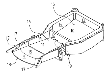
The casting trough according to figure 1 a has a curved bottom 16, side walls
14
and a rear wall 13. The choke brick 12 is placed between the spout, in this
case
the spout brick 15, and the rear wall 13. The choke brick 12 divides the space
defined by the bottom and walls to the casting trough forepart 11 and the
casting trough back end 10. The notches made at the bottom edge of the choke
brick 12 and the bottom 16 of the casting trough define the slots 19 through
which the molten metal flows from the back end 10 to the forepart 11. The
height of the choke element is advantageously chosen so that it extends from
the bottom of the casting trough to at least the surface level of the melt,
while
the casting trough is in the filling position. When feeding molten metal in
the
casting trough, the metal is divided between the casting trough forepart 11
and
back end 10. Advantageously the molten metal is fed in the space 10. The
spout brick 15 has vertical side walls 17 and a pouring surface 9. The pouring
surface 9 is curved downwards and widened towards the spout edge 18. When
viewed from above, the spout edge 18 is curved, and the pouring surface 9 is a
conic section. The volume of the back end 10 of the casting trough according
to
the embodiment illustrated in figure 1 is larger than the volume of the
forepart
11, because the casting trough is widened at the choke brick 12 towards the
rear wall 13. This arrangement makes it possible that a remarkably larger
quantity of molten metal can be fed behind the choke brick in the space 10
than
in the space 11.
CA 02564631 2006-09-11
WO 2005/095027 PCT/FI2005/000138
Figure 1 b illustrates a casting trough according to a preferred embodiment of
the invention, provided with a curved bottom 16, side walls 14 and a rear wall
13. The spout brick 15 has vertical side walls 17 and a pouring surface 9. The
pouring surface 9 is curved downwardly and widened towards the spout edge
18. When viewed from above, the spout edge 18 is curved,'and the pouring
surface 9 is a conic section.
In the casting troughs according to figures 1 a and 1 b, the lining is made of
fireproof brickwork, and the frame is made of steel.
Figures 2a and 2b show a casting trough 30 and in front of it a casting mold
for
a copper anode 24. The casting mold 24 has an anode-shaped casting cavity
31. In the embodiment according to figure 2, the side walls 27 of the casting
trough continue in parallel and in a straight line as far as the spout brick
25 of
the rear wall 23, in which case the bottom 26 of the casting trough is
essentially
rectangular when viewed from the top. The choke brick 22 is arranged at right
angles to the side walls 27, and it extends from side wall to side wall. The
bottom edge of the choke brick 22 is provided with two notches that define the
slots left between the bottom 26 and the choke brick 22, through which slots
the
molten metal flows from the space 20 to the space 21. Against the side walls
27, there are arranged three pairs of upwardly directed support beams 39 for
fitting the spout brick 22 in the desired spot in between the rear wall 23 and
the
spout brick 25. When necessary, the location of the choke brick can be
adjusted at the spots defined by the three pairs of support beams. The choke
brick 22 is supported in place by two wedges 61 and fastening elements 62.
The arrows 28 show the direction of the molten metal flow as, well as
turbulences when the metal flows out of the casting trough 30 and settles in
the
cavity 31 of the casting mold 24.
Figures 3a, 3b and 3c illustrate the embodiment of the invention seen in
figures
2a and 2b, viewed along the section A - A. In figure 3a, the casting trough 30
is
CA 02564631 2006-09-11
WO 2005/095027 PCT/FI2005/000138
11
in the filling position, filled with molten metal 32. In figure 3b, the
casting trough
30 is inclined for pouring, and the molten metal 32 flows from the casting
trough
30 to the casting mold 24. In figure 3c, the casting trough 30 is returned to
the
filling position after pouring. The bottom 26 of the casting trough is curved,
so
that the height hm of the molten metal remains low in relation to the length
of
the casting trough, when measured from the rear wall 23 to the spout brick 25.
The spout brick 40 according to figure 4 is fitted in the casting trough. The
spout brick can be manufactured for example separately, by casting of
fireproof
material. The spout brick comprises a pouring surface 49 and a bottom element
41 fitted in parallel with the casting trough bottom. The pouring surface 49
of
the spout brick is curved downwardly from the casting trough bottom, and it is
a
conic section. The spout brick has essentially vertical side walls 42, 43. At
the
pouring surface, the side walls 43 are lowered towards the pouring surface
edge 45. The corner radius of the edge between the surfaces 41 and 49 is
preferably 0.5 - 800 mm.
Figures 4a and 4b illustrate a spout brick according to figure 4 when
installed in
front of the casting mold 44 and above it, in operating position. The pouring
surface 49 of the spout brick is widened towards the pouring edge 45. The
radius of curvature r of the pouring edge is proportioned to the width A of
the
casting mold cavity, and the length of the radius of curvature r is
advantageously 0.2 - 6 times the measure of A. The length B of the pouring
surface depends on the chosen brick height E in proportion to the casting
mold,
and on the angle epsilon (s) of the cone surface in relation to the direction
of
the bottom element 41 of the spout brick. The size of the angle epsilon (E) is
advantageously within the range 12 - 55 degrees. The width C of the spout
brick is advantageously 0.3 - 0.95 times the width A of the casting mold
cavity,
particularly advantageously 0.5 - 0.8 times the width A of the casting mold
cavity. The measure D of the spout brick surface 41 is chosen so that the
spout
brick is suitably integrated with the rest of the design of the casting
trough. The
operation of the spout brick is advantageously affected by minimizing the
CA 02564631 2006-09-11
WO 2005/095027 PCT/FI2005/000138
12
pouring height F. The pouring height can be for example within the range 70 -
400 mm, preferably 130 - 200 mm. The width K of the pouring edge 45 is
advantageously 0.5 - 0.98 times the width A of the casting mold cavity,
preferably 0.6 - 0.7 times the width A of the casting mold cavity.
The choke brick 50 illustrated in figures 5a and 5b is provided with denting
formed by three notches 51, 52, 53. The height of the choke brick extends at
least from the bottom of the casting trough to the level of the top edge of
the
side walls. In the casting of copper, the height h, of the notches is
preferably
- 100 millimeters. The total area of the notches is preferably within the
range 1500 - 17000 square millimeters. In practical work, the total area of
the
notches can easily be increased simply by breaking some dents off the brick.
Consequently, for finding a suitable notch area, it is advantageous to start
the
casting with a choke brick provided with several dents. From the point of view
of
pouring a cast according to the invention, the essential factors are the
height
and total area of the notch or notches in the choke brick. The sum of the
notch
widths 11 +12+13 is preferably 0.05 - 0.9 times the brick width It. The
thickness dt
of the brick can be less than 5 millimeters or over 100 millimeters,
advantageously it is 5 - 100 mm.
For a man skilled in the art, it is obvious that the various embodiments of
the
invention are not restricted to the ones described above, but may vary within
the scope of the appended claims.