Note: Descriptions are shown in the official language in which they were submitted.
CA 02564680 2013-02-19
IMPROVED MICRO-MACHINED SUSPENSION PLATE WITH
INTEGRAL PROOF MASS FOR USE IN A SEISMOMETER OR
OTHER DEVICE
FIELD OF THE INVENTION
The invention relates to seismic instrumentation in general. More
particularly,
the invention is related to an improved micro-machined suspension plate having
an
integral proof mass and a method of fabrication for the same that may be
utilized in a
seismometer (velocimeter), an accelerometer, or other similar device.
DESCRIPTION OF THE PRIOR ART
U.S. Patent publication No. US 2003/0140699 Al published July 31, 2003,
entitled "MICRO-MACHINED ACCELEROMETER", was filed on January 5, 2002 and
discloses a novel construction of an accelerometer or seismometer using an in-
plane
suspension geometry having a suspension plate and at least one fixed
capacitive plate.
In contrast to conventional seismometers, which utilize a spring supporting a
1
CA 02564680 2006-10-24
WO 2006/059231 PCT/1B2005/003998
distinct proof mass on an external frame, the micro-machined suspension plate
is
formed from a single piece of material to include the external frame, a pair
of
flexural elements and an integral proof mass interposed between the flexures.
The flexural elements allow the proof mass to move in one direction, the
sensitive
direction, in the plane of suspension, while restricting as far as possible
movement in all the other off-axis directions.
The new in-plane design also includes a displacement transducer for
determining relative motion of the proof mass. This transducer includes
accurately placed drive electrodes, preferably positioned on the proof mass,
and
corresponding pickup electrodes located on the fixed capacitive plate.
A preferred embodiment of this design for a low-noise seismometer allows
for the production of a system having a resonance frequency of approximately
10Hz. However, in order to utilize such a design over a bandwidth of
approximately 100 Hz, is it desirable to ensure that spurious oscillation
frequencies, in both the sensitive direction, and in the off-axis directions
(namely
the orthogonal in-plane direction, and the orthogonal out-of-plane directions)
are
suppressed by the feedback system or do not exist in the system. Otherwise,
they will interfere with accurate operation of the system over the full
bandwidth.
These considerations apply equally to other types of velocity and acceleration
sensors, with generally a large desired margin between the top of the sensor
bandwidth and the first spurious resonance, in any direction.
There are known techniques for rejecting any signals or oscillations of the
proof mass for spurious modes in the off-axis directions. Unfortunately, many
of
2
CA 02564680 2013-02-19
these known techniques effect the geometry, placement and positioning of the
drive and
pick-up electrodes. Moreover, while these techniques can allow for stable
operation,
they may still result in undesirable artifacts in the amplitude and phase
response of the
system. Accordingly, an alternate approach is needed in order to ensure that
other
resonances do not exist within the desired bandwidth.
Additionally, the plan structure disclosed in U.S. Patent publication No.
2003/0140699 Al requires that the gap between the drive and pickup electrodes
must be
carefully controlled. This implies that the out-of-plane motion of the proof
mass is
suppressed as far as possible.
For accelerations equally impressed along the sensitive axis and an off-axis,
the
off-axis displacement is related to the sensitive-axis displacement by the
square of the
ratio of the fundamental frequency to the lowest frequency of any off-axis
modes.
Accordingly, it is desirable to keep the ratio of these two frequencies as low
as possible
to minimize the undesirable displacement in the off-axis direction.
Additionally, the in-place structure described in the above U.S. Patent
publication
may be fractured or damaged due to extreme external shock or vibration. This
problem
occurs most often when the device is not powered and the feedback electronics
are not
active, in which case there is no active damping of the system. This might
occur, for
example, during the packaging and transport of such a device, or in the
fabrication
processing after the spring mass geometry has been completed. Although the use
of a
gas-filled cavity may provide some camping effects, this alone may not be
sufficient to
3
CA 02564680 2013-02-19
minimize the effects of such external shock or vibration. Accordingly, it is
desirable to
have a non-powered dampening system that minimizes the effects of shock to the
system
that may occur when the system is in a non-powered/non-operational state.
SUMMARY OF THE INVENTION
In the present invention, the off-axis motion of the proof mass is minimized
through the use of intermediate frames. Accordingly, the present invention
improves
upon the design set forth in the U.S. Patent publication noted above by
utilizing
intermediate frames disbursed within and between the flexural elements in
order to
produce a system where the frequency of the off-axis modes are as many
multiples as
possible of the resonant frequency of the system, while minimizing the
reduction in the
frequencies of spurious modes along the sensitive axis. This eliminates any
spurious
modes over a much larger bandwidth allowing the production of a device with a
flat
response over such bandwidth. The solution is easy to implement in the
preferred
embodiment of the suspension, without any effect on or additional
complications to the
design of the electronics used in the system. As a result of the increased out-
of-plane
rigidity, these frames minimize variation in the transducer gap between the
fixed and
proof-mass electrodes.
The number of frames to be used in determined as a function of both the
desired of bandwidth over which spurious modes are to be eliminated and the
4
CA 02564680 2006-10-24
WO 2006/059231 PCT/1B2005/003998
desired operational parameters of the system. More particularly, as the number
of frames is increased, the off-axis spurious resonant modes are pushed up in
frequency, thus increasing the overall effective bandwidth over which the
device
may operate without the occurrence of any spurious resonant frequencies.
However, as the number of frames is increased, the frequency of spurious modes
along the sensitive axis is reduced, due to the additional mass of the frames.
Accordingly, a balance is struck between the desired elimination of off-axis
and
on-axis spurious resonant frequencies over an operational.
The intermediate frames can be provided with motion stops, so that -tinder
overload conditions the frames engage each other, preventing further relative
motion, before the flexures make any contact or become overstressed. These
stops thus minimize the chance of fracture or the irreversible surface bonding
of
portions of the flexure ("stiction").
The invention also preferably includes a dampening structure that is
highly effective during non-powered/non-operational states (i.e. when the
feedback control system is not powered and does not provide any dampening).
Preferably, this dampening structure includes a spring/gas dampening structure
configured to provide damping during non-powered states.
In a preferred embodiment, the structure preferably includes a trapezoidal
shaped piston and a corresponding engagement cylinder. The damping structure
is positioned to engage between the outermost intermediate frame and the
external frame as the springs are overloaded. In this way, and as explained
earlier, the piston or cylinder is placed at a traversal distance which
extends
CA 02564680 2006-10-24
WO 2006/059231 PCT/1B2005/003998
iurtner tnan any intermecuate flexural elements such that it will not make
contact with any of these flexural elements. The piston or cylinder faces
outward, and a corresponding cylinder or piston is then positioned on the
inner
surface of the outer frame of the suspension plate, facing inward toward the
proof
mass.
As the most outward intermediate frame approaches the inner surface of
the outer frame of the suspension plate, the piston will engage the cylinder,
thereby providing a dampening effect before the intermediate frame can contact
the surface of the external frame of the suspension. In a preferred embodiment
where the suspension plate is contained and submersed within a gaseous
environment, the pressure of the gas will increase within the confined space
of
the cylinder as the piston moves further into the cylinder. The resulting
viscous
gas flow will act as a damping force, slowing the outer intermediate frame
away
from the external frame of the suspension. In an alternative embodiment where
no gas is used, the piston and cylinder may be coupled using a dissipative
material disposed between the piston and the cylinder such that the material
is
compressed as the piston moves further into the cylinder, thereby providing a
damping force which slows the motion of the outer intermediate frame toward
the external frame.
BRIEF DESCRIPTION Or THE DRAWINGS
FIG. 1 illustrates a cross-sectional diagram of a seismometer having a
suspension plate and two capacitive plates, with a centrally located proof
mass
6
CA 02564680 2006-10-24
WO 2006/059231 PCT/1B2005/003998
supported. Dy flexural elements on each side utilized in a known, prior-art
micro-
machined in-plane suspension geometry;
FIG. 2 illustrates a proof mass, flexural elements and intermediate frames
as used in a preferred embodiment of a micro-machined in-plane suspension
geometry;
FIG. 3 illustrates the spurious mode rejection ratio for in-axis and out-of-
axis modes as the number of intermediate frames is increased in a preferred
embodiment having six flexural elements on each side of the proof mass.
FIG. 4 illustrates the spurious mode rejection ratio for in-axis and out-of-
axis modes as the number of intermediate frames is increased in a preferred
embodiment having twenty four flexural elements on each side of the proof
mass;
FIG. 5 illustrates a perspective view of a suspension plate 500 having a
spring/gas dampening structure 510 in accordance with a preferred embodiment
of the present invention;
FIG. 6 illustrates a close-up view of a preferred embodiment of the
spring/gas dampening structure;
FIG. 7 illustrates a close-up view of a piston used in an alternative
embodiment of the spring/gas damping structure;
FIG. 8 illustrates an another close-up view of an alternative piston used in
an alternative embodiment of the spring/gas damping structure; and
FIG. 9 illustrates a mask set that has been deliberately biased so that the
flexural elements are "pre-tensioned" when lying flat.
7
CA 02564680 2013-02-19
DETAILED DESCRIPTION OF THE PREFERRED EMBODIMENTS
As explained earlier (U.S. Patent publication 2003/0140699 entitled "MICRO-
MACHINED ACCELEROMETER") discloses an improved micro-machined
suspension plate which may be utilized in an accelerometer, seismometer
(velocimeter)
and/or other similar device.
The suspension plate is formed of and includes a revolutionary, in-plane
suspension geometry rather than a traditional - spring design. More
particularly, the
suspension plate is micro-machined to form a central proof mass and flexural
elements
located on opposite sides of the proof mass. FIG. 1 illustrates a cross-
sectional diagram
of a seismometer 1 having a suspension plate 2 and two capacitive plates 3a-b
(alternatively, the device can have one capacitive plate), with a centrally
located proof
mass 8 supported by flexural elements 6 utilized in a known, prior-art micro-
machined
in-plane suspension geometry, as described and set forth in the U.S. Patent
publication
noted above.
As shown in FIG. 1, the proof mass 8 is centrally located and surrounded by a
hollow cavity 4. The flexural elements 6 extend from opposite directions and
allow the
proof mass 8 to move in one direction, in the plane of suspension, but
suppress motion
of the proof mass in all other directions. These flexural elements 6 represent
a
significant improvement over the conventional use of a mechanical cantilevered
spring
design for supporting the proof mass.
The use of these flexural elements 6 allows for the production of a system
having
a resonance frequency of 10Hz or less. However, it is desirable that this
design be
able to operate over a bandwidth of approximately 100 Hz (i.e. a
8
CA 02564680 2006-10-24
WO 2006/059231 PCT/1B2005/003998
bandwidth of 10x the resonant frequency). However, spurious resonant
frequencies may exist over the bandwidth. These spurious resonant frequencies
will have an adverse effect on the operation of the system. Accordingly, it is
desirable to ensure that the spurious modes are suppressed and do not exist in
the system.
There are known techniques for rejecting any signals that may result from
off-axis spurious modes. One such technique adjusts the positioning of the
drive
and pick-up electrodes, such that the sensitivity to motion in the spurious
mode
is greatly attenuated by the design of the geometrical pattern of the
electrodes.
For example a symmetrical centered structure can show a very good rejection of
a torsional motion. While this technique can allow for stable operation, it
will still
result in undesirable artifacts in the frequency and phase response of the
system.
Accordingly, an alternate approach for ensuring that other mechanical
resonances do not exist within the desired bandwidth is needed.
As explained earlier, the suspension plate shown in FIG. 1 is ideally paired
with at least one capacitive plate for use in a seismometer, an accelerometer,
a
velocimeter, or another similar device. In such a case, the capacitive plate
is
preferably configured to include pickup electrodes 10 and the proof mass is
equipped with drive electrodes 11. This in-plane structure requires that the
drive electrodes and the pickup electrodes be correspondingly spaced, with the
same periodicity in order to ensure the accuracy of operation of the system.
The
periodicity of these electrodes affects the dynamic and static range of the
system.
9
CA 02564680 2006-10-24
WO 2006/059231 PCT/1B2005/003998
The- out-or-pian.e sag of the proof mass must be accurately controlled in
order to produce the proper geometry of the seismometer position transducer by
ensuring accurate spacing between the drive and pickup electrodes.
Unfortunately, the proof mass will suffer the normal effects of gravity and
may
experience an out of plane sag due to any cross-axis component of
gravitational
forces. Similarly, any off-axis accelerations can cause unwanted motion of the
proof mass. The off-axis displacement is related to the in-plane displacement
by
the square of the ratio of the fundamental frequency divided by the frequency
of
the spurious out of plane mode. Accordingly, in order to minimize the out of
plane sag, it is desirable to keep the ratio of these two frequencies as low
as
possible so that the spurious mode frequency is as high a multiple of the
fundamental frequency as possible.
The present invention accomplishes the objectives of ensuring that other
mechanical resonances do not exist within the desired bandwidth while
minimizing out-of-plane sag by utilizing intermediate frames which are
disbursed
within the flexural elements in order to produce a system where the frequency
of
the first spurious mode is preferably at least ten times the resonant
frequency of
the system.
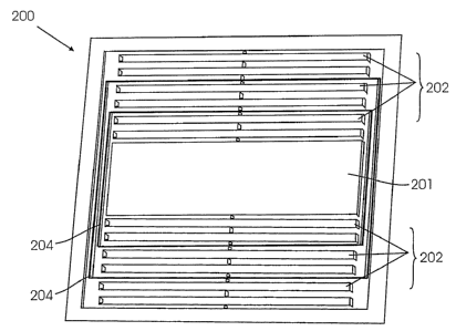
FIG. 2 illustrates a suspension plate having a proof mass 201 supported by
flexural elements 202 and further having intermediate frames 204 inter-
disposed there between, in accordance with a first preferred embodiment of the
present invention. Use of these intermediate frames 204 eliminates any
spurious
modes over a much larger bandwidth and allows the production of a device with
a
CA 02564680 2006-10-24
WO 2006/059231 PCT/1B2005/003998
liat response over the region of such bandwidth. The intermediate frames 204
also provide additional support to the proof mass 201 and help reduce the out
of
plane sag.
As shown in FIG. 2, the intermediate frames 204 are integral to and are
formed within the suspension plate 200 using the same micro-machining
techniques used for forming the flexural elements 202. Accordingly, the
implementation of these intermediate frames is easy to implement, without any
effect on or additional complications to the design or fabrication of the
system.
In a preferred embodiment, the present invention may utilize any number
of intermediate frames, with the number of frames determined as a function of
both the desired bandwidth over which spurious modes are to be eliminated and
the desired operational parameters of the system. More particularly, as the
number of intermediate frames is increased, a broader range of spurious
resonant frequencies are eliminated, thus increasing the overall effective
bandwidth over which the device may operate without the occurrence of any
spurious resonant frequencies. However, as the number of intermediate frames
is increased, the size of the proof mass is necessarily reduced in the limited
space, thereby reducing the resonant frequency of the system. Further, the
frames themselves introduce additional spurious sensitive-axis modes, whose
frequency drops as the frame mass relative to the suspension mass increases.
Accordingly, a desirable balance is struck between the desired elimination
from
the bandwidth of spurious out-of-plane and sensitive-axis modes.
11
CA 02564680 2006-10-24
WO 2006/059231 PCT/1B2005/003998
The first step in selecting the optimum number of intermediate frames to
utilize in any particular system is to select the fundamental operational
frequency of the system. Having selected a fundamental operational frequency
of
the spring mass system a very desirable optimization is to move the spurious
frequencies, either in axis or out of axis, to as high a frequency as possible
in
relation to the fundamental frequency of the spring mass system as this
increases the useable bandwidth of the device. The in-axis first spurious mode
decreases/deteriorates as the mass of each frame, inframe, relative to mass of
each
set of flexural elements between the intermediate frames, mflex, increases.
The
rejection ratio (Rmassioad) for this effect is given by the empirically
derived
equation:
Rmassload= 1
1 + 0.124(mframe/maex) .82
As the total number of intermediate frames is increased, mframelmflex becomes
larger, as the suspension is further subdivided and mflex necessarily
decreases.
Hence the in-axis spurious frequency decreases as number of intermediate
frames increases. The out-of-axis resonant frequency is given by
four 1
oe
fin 441springs2 ¨ 1
where nsprings is the number of flexural element in each set of flexural
elements
between each intermediate frame. The constant of proportionality is almost
completely independent of the number of frames. In this case, nsprings falls
as the
number of intermediate frames increases (for a given total number of flexural
12
CA 02564680 2006-10-24
WO 2006/059231 PCT/1B2005/003998
elethents), the out-of-a,xiS Spurious frequency increases as the number of
frames
increases. As our goal is the highest possible "spurious-free" frequency range
we
can optimize the number of frames to achieve this goal. Keeping all other
parameters fixed, we can now plot the two effects for a particular case.
In a first preferred embodiment, we will assume we have a total of 6
flexural elements on each side of the proof mass in order to achieve a desired
frequency response and for which we wish to determine the optimal or best
number of frames for suppressing spurious frequencies given our desired
operational frequency.
13
CA 02564680 2006-10-24
WO 2006/059231 PCT/1B2005/003998
These 6 flexural elements can be divided into the following numbers of sets
as follows:
nsets nsprings nframes
1 6 0
2 3 1
3 2 2
6 1 5
For our case we can now plot the in-axis and out-of-axis frequencies in
relation to
the fundamental frequency, the so called "spurious-mode rejection ratio".
FIG. 3 illustrates the spurious mode rejection ratio for in-axis and out of
axis frequencies as the number of intermediate frames is increased. We can see
from FIG. 3 that in order to maximize the rejection ratio for both in-axis and
out
of axis frequencies, the number of frames that should be incorporated into the
design is 5, one between each of the 6 flexural elements. As the rejection
ratio
rises more steeply for the off-axis case than it falls for the on-axis case,
there will
be on overall tendency for more frames to produce better performance.
If we take an example with more flexural elements we can calculate more
data points and see again the convergence of the "on-axis" and "off-axis"
modes
to give an improved overall rejection ratio. For example, in a second
preferred
embodiment let us assume we have 24 flexural elements in order to achieve a
desired frequency response. For this case, let us again plot the in-axis and
out-of-
axis frequencies in relation to the fundamental frequency, the so called
"spurious-mode rejection ratio". FIG. 4 illustrates the spurious mode
rejection
ratio for in-axis and out of axis frequencies as the number of intermediate
frames
is increased. We can see from FIG. 4 that in order to maximize the rejection
ratio
14
CA 02564680 2006-10-24
WO 2006/059231 PCT/1B2005/003998
tIle maximum number of frames utilized in the design should be approximately
23, one between each intermediate frame should be incorporated into the
design.
It is important to note that in some designs it may be desirable for other
system considerations to not optimize for an equivalent spurious mode both for
the in-axis and off-axis, but to allow say a lower off-axis spurious mode
compared
with the in-axis mode. This could be used for example when the off-axis is
suppressed by the Displacement Transducer geometry, while the in-axis mode is
not. The techniques presented can be used for any desired optimization.
The invention also preferably includes a dampening structure that is
highly effective during non-powered/non-operational states (i.e. when the
feedback control system is not powered and does not provide any dampening).
Preferably, this dampening structure includes a spring/gas dampening structure
configured to provide damping during non-powered states. FIG. 5 illustrates a
perspective view of a suspension plate 500 having a spring/gas dampening
structure 510 in accordance with a preferred embodiment of the present
invention.
As shown in FIG. 5, each of the intermediate frames 501 is preferably
larger (longer) in length then the flexural elements 503 disposed between each
of the frames, with each frame traversing a larger portion of the internal
cavity
502. The intermediate frames are also sufficiently rigid, but as light as
possible,
in order to suppress out of plane movement of the proof mass while also
suppressing spurious resonant frequencies without breaking or fracturing. The
intermediate frames 501 are designed to physically contact with each other
CA 02564680 2006-10-24
WO 2006/059231 PCT/1B2005/003998
oeiore tile flexural. elements 5U6 interspersed between them are compressed
sufficiently to cause damage to the flexural elements 503.
In order to prevent fracturing and/or damage due to extreme external
shock or vibration, the invention preferably further includes the specially
formed
spring/gas dampening structure 510, which provides additional damping to the
system during non-powered states.
Turning to FIG. 6, there is shown a close-up view of a preferred
embodiment of the spring/gas dampening structure 510. As shown, the
preferred embodiment preferably includes one or more trapezoidal shaped
pistons 601 and engagement apertures 602. In a preferred embodiment, a piston
601 is preferably positioned on the last (most outward) intermediate frame
605,
facing outward, and the corresponding engagement aperture 602 is then
positioned on the inner surface of outer frame of the suspension plate 607,
facing
inward. As the most outward intermediate frame 605 approaches the inner
surface of the outer frame of the suspension plate 607, the piston 601 will
engage
and insert into the aperture 602, thereby providing a dampening effect before
the intermediate frame can contact the surface of the outer frame of the
suspension plate.
In a preferred embodiment, the cavity of the suspension plate is preferably
filled with a non-conductive gas such as air or nitrogen. As the outermost
intermediate frame 605 moves toward the inner surface of the outer frame of
the
suspension plate 607, the piston 601 engages with and inserts into the
engagement aperture 602. As the piston recedes further into the aperture, the
16
CA 02564680 2006-10-24
WO 2006/059231 PCT/1B2005/003998
gas"within tne engagement aperture increases in pressure, causing a force to
be
exerted against the piston and slowing the motion of the intermediate frame
until, possibly over multiple oscillations of the spring mass system, it comes
to
rest, thereby preventing damage to the flexural elements.
Alternatively, the cavity within the suspension plate may be evacuated. In
this case, the spring/gas dampening structure is preferably comprised of a
aperture and a corresponding piston wherein the piston is actually formed of
two
separate portions coupled together using a small resistance spring. FIG. 7 is
a
close-up view of such an alternative embodiment of a piston 700 used in a
spring/gas damping structure, wherein the piston is formed of two separate
portions coupled together using a small resistance spring. As shown, the
piston
includes a first half portion 701 and a second half portion 703, which are
coupled
together using a small resistance springs 705. In normal operation when the
pistons are not engaged these two spring elements are separate, but as the
parts
contact they form a spring element. As the piston 700 inserts further into the
aperture of the spring/gas dampening structure, second half portion 703 of the
piston is pushed against and closer to the first half portion 701 while the
resistance spring provides a force against the second half portion 703. As the
second half portion 703 moves closer to the first half portion 701, the
resistance
from the spring increases. This spring motion can be used both to dissipate
energy, but also to act as an energy store to disengage the first and second
half
portions to prevent them "sticking" together by the force of stiction and
preventing the device from functioning as a spring mass system. Alternatively,
a
17
CA 02564680 2013-02-19
layer or damping material such as a visco-elastic polymer 706 may be inserted
between
the first half portion 701 and the second half portion 703, in place of or in
addition to
the resistance spring, as shown in FIG. 6. A visco-elastic material block 707
can also
be deposited on top of the spring element 705 to provide damping and energy
loss in the
spring.
For practical production of a seismometer device having a suspension plate and
two conductive or capacitive plates, as described in U.S. Patent publication
No.
2003/0140699, it is highly desirable that a single device geometry can be used
to produce
all three components of the sensor - i.e. the capacitive plates and the
suspension plate.
In order to accomplish this, all three plates are preferably arranged in a
"Galperin"
orientation so each sees the same gravity vector. Due to the geometry of the
device it
is important to ensure for optimal operation and design that when exposed to
this gravity
vector the proof mass is centered. If the suspension plate is manufactured
separate from
the capacitive plates, then the gravity force on the proof mass will effect
the centering
of the proof mass relative to each of the other capacitive plates and this
will affect the
readings as to each plate when the whole device is formed.
To ensure that the proof mass is centered after production, the mask set is
deliberately biased so that the flexural elements are "pre-tensioned" when
lying flat. This
pre-tensioning is such that when orientated at the "Galperin" orientation, or
angle of 54.7
degrees, the spring mass system is centered. When the material is removed by a
method
such as Deep Reactive Ion Etching (DRIE) the spring assumes a centered
position
at the Galperin angle of 54.7 degrees. The
18
CA 02564680 2006-10-24
WO 2006/059231 PCT/1B2005/003998
preqenaidiling'can"
be daltulated either analytically or using Finite Element
Analysis, both techniques are well know to those skilled in the art, such that
the
pattern is the same deflection pattern that would be observed in a released
symmetrical structure when subject to an acceleration of opposite magnitude
and
direction to that the system when orientated at the Galperin position. This
level
of pre-tensioning will then almost exactly counterbalance the gravity vector
in
the Galperin orientation so that the mass will be nearly perfectly centered.
FIG. 9
illustrates a mask set that has been deliberately biased so that the flexural
elements are "pre-tensioned" when lying flat.
Finally, for optimum performance, the center of mass of the proof mass
and the center of action of the actuator should be collocated. In addition the
direction of motion of the proof mass and the direction of force of the
actuator
should be collinear. The device can be produced with a displacement transducer
and magnetic actuator both formed on a single surface of the device. This
minimizes processing cost, but allows development of off-axis forces and
responses. There are two methods for producing the desired geometry and a
further method for compensating for any residual off-axis effects. For the
first
method, the magnetic actuator is fabricated on both sides of the device. In
this
design the off-axis torque tends to balance out, at the cost of a considerably
more
complex fabrication process. For the second method, the actuator and
transducer
are fabricated on different sides of the proof mass and a duplicate of the ,
suspension (frame, spring and proof mass) is bonded on the actuator side of
the
19
CA 02564680 2013-02-19
proof mass. Thus composite proof mass has an actuator at its center of mass,
again at
the cost of a considerably more complex fabrication process.
The presently disclosed embodiments are therefore to be considered in all
respects
as illustrative and not restrictive, the scope of the invention being
indicated by the
appended claims, rather than the foregoing description, and all changes which
come
within the meaning and range of equivalency of the claims are therefore
intended to be
embraced herein.