Note: Descriptions are shown in the official language in which they were submitted.
CA 02564888 2006-10-27
WO 2005/107003 PCT/EP2004/004779
1
Differential pressure control method
for Molten Carbonates Fuel Cell power plants
Field of the invention
The present invention relates to pressurised molten
carbonate fuel cell power generation systems which
directly converts chemical energy of a fuel into
electrical energy.
Background of the invention
A fuel cell is a device that uses hydrogen (or hydrogen-
rich fuel) and oxygen to create electricity by an
electrochemical process.
A single fuel cell consists of an electrolyte sandwiched
between two thin electrodes (a porous anode and cathode).
While there are different fuel cell types, all work on
the same principle: hydrogen, or a hydrogen-rich fuel, is
fed to the anode where a catalyst separates hydrogen's
negatively charged electrons from positively charged ions
(protons ) .
CA 02564888 2006-10-27
WO 2005/107003 PCT/EP2004/004779
2
At the cathode, oxygen combines with electrons and, in
some cases, with species such as protons or water,
resulting in water or hydroxide ions, respectively.
For polymer exchange membrane (PEM) and phosphoric acid
fuel cells, protons move through the electrolyte to the
cathode to combine with oxygen and electrons, producing
water and heat.
For alkaline, molten carbonate, and solid oxide fuel
cells, negative ions travel through the electrolyte to
the anode where they combine with hydrogen to generate
water and electrons. The electrons from the anode side of
the cell cannot pass through the membrane to the
positively charged cathode; they must travel around it
via an electrical circuit to reach the other side of the
cell. This movement of electrons is an electrical
current.
The amount of power produced by a fuel cell depends upon
several factors, such as fuel cell type, cell size, the
temperature at which it operates, and the pressure at
which the gases are supplied to the cell. Still, a single
fuel cell produces enough electricity for only the
smallest applications. Therefore, individual fuel cells
are typically combined in series into a fuel cell stack.
CA 02564888 2006-10-27
WO 2005/107003 PCT/EP2004/004779
3
A typical fuel cell stack may consist of hundreds of fuel
cells.
Direct hydrogen fuel cells produce pure water as the only
emission. This water is typically released as water
vapor.
Fuel cell systems can also be fueled with hydrogen-rich
fuels, such as methanol, natural gas, gasoline, or
gasified coal. In many fuel cell systems, these fuels are
passed through "reformers" that extract hydrogen from the
fuel. Onboard reforming has several advantages:
First of all it allows the use of fuels with higher
energy density than pure hydrogen gas, such as methanol,
natural gas, and gasoline. Further, it allows the use of
conventional fuels delivered using the existing
infrastructure (e.g., liquid gas pumps for vehicles and
natural gas lines for stationary source).
High-temperature fuel cell systems can reform fuels
within the fuel cell itself - a process called internal
reforming - or can use waste heat produced by the fuel
cell system to sustain the reforming endothermic
reactions (integrated reforming), as disclosed in EP-A-1
321 185.
CA 02564888 2006-10-27
WO 2005/107003 PCT/EP2004/004779
4
In addition, impurities in the gaseous fuel can reduce
cell efficiency.
The design of fuel cell systems is quite complex and can
vary significantly depending upon fuel cell type and
application. However, most fuel cell systems consist of
four basic components:
- A fuel processor
- An energy conversion device (the fuel cell or fuel
cell stack)
- A power converter
- Heat recovery system (typically used in high-
temperature fuel cell systems used for stationary
applications)
Other components and subsystems are foreseen to control
fuel cell humidity, temperature, gas pressure, and
wastewater.
The first component of a fuel cell system is the fuel
processor. The fuel processor converts fuel into a form
useable by the fuel cell. If hydrogen is fed to the
CA 02564888 2006-10-27
WO 2005/107003 PCT/EP2004/004779
system, a processor may not be required or it may be
reduced to hydrogen storage and feeding systems.
If the system is powered by a hydrogen-rich conventional
5 fuel such as methanol, gasoline, diesel, or gasified
coal, a reformer is typically used to convert
hydrocarbons into a gas mixture of hydrogen and carbon
compounds called "reformate." In many cases, the
reformate is then sent to another reactor to remove
impurities, such as carbon oxides or sulfur, before it is
sent to the fuel cell stack. This prevents impurities in
the gas from binding with the fuel cell catalysts. This
binding process is also called "poisoning" since it
reduces the efficiency and life expectancy of the fuel
cell.
Some fuel cells, such as molten carbonate and solid oxide
fuel cells, operate at temperatures high enough that the
fuel can be reformed in the fuel cell itself or can use
waste heat produced by the fuel cell system to sustain
the reforming endothermic reactions.
Both internal and external reforming release carbon
dioxide, but less than the amount emitted by internal
combustion engines, such as those used in gasoline-
CA 02564888 2006-10-27
WO 2005/107003 PCT/EP2004/004779
6
powered vehicles, due to high conversion efficiency
available with fuel cells.
Fuel cell systems are not primarily used to generate
heat. However, since significant amounts of heat are
generated by some fuel cell systems - especially those
that operate at high temperatures such as solid oxide and
molten carbonate systems - this excess energy can be used
to supply thermal energy to sustain reforming reactions,
to produce steam or hot water or converted to electricity
via a gas turbine or other technology. This increases the
overall energy efficiency of the systems.
A prior-art device of the type disclosed in the present
case is, for example, a fuel cell device as described in
the US application 4,904,547.
Here, the pressure difference controlling method is
schematically illustrated in fig. 1, where a switching
valve 11 connects a nitrogen line and a fuel line and is
installed outside a vessel while a switching valve 12
connects the nitrogen line and an air line.
The first pressure controller 13 applies a set signal to
a fuel differential pressure control valve 4 upon
receiving a signal from the first differential pressure
detector which detects the differential pressure between
the vessel pressure and the anode exhaust. A second
CA 02564888 2006-10-27
WO 2005/107003 PCT/EP2004/004779
7
pressure controller 15 applies a set signal to the
cathode differential pressure control valve 4 upon
receiving a signal from the second differential pressure
detector, which detects the differential pressure between
the vessel pressure and the cathode exhaust.
During the functioning, the system pressure is regulated
by the pressure control valve 8 and the controllers for
the differential control pressure vessel-anode and
vessel-cathode are the controller 13 and 15 respectively;
switching valves 11 and 12 are closed.
In case of a urgent system stop, valve 7, 3, 5 close,
while switching valves 11 and 12 open, allowing the
natural decrease of the nitrogen pressure in the vessel.
Consequently the pressures of the respective lines lower
to the normal pressure according to the pressure control
system. In this way the fuel cell can be stopped in a
short time with a small amount of nitrogen.
However, the above-described conventional method using
the differential pressure control valve cannot ensure
that the differential pressure always stays in a
predetermined range when pressure varies rapidly or
CA 02564888 2006-10-27
WO 2005/107003 PCT/EP2004/004779
8
troubles occur in the valves or in the differential
pressure meters or an air feed line, a power source or
other components. Moreover, the differential pressure
control between anode and vessel and between cathode and
vessel are independent so that if some problems occur to
a single line, there could be an increase in differential
pressure between electrodes, causing the breakage of a
fuel cell.
Due to the high operating temperature of Molten
Carbonates Fuel Cells (hereafter called MCFC), high
temperature control valves have to be used, what
constitutes an high impact on the total costs of the
plant.
Therefore, this conventional method has a problem in
reliability and the components employed are very
expensive.
Sunmmary of the invention
It is therefore an object of the present invention to
provide a MCFC system which allows to avoid the technical
CA 02564888 2006-10-27
WO 2005/107003 PCT/EP2004/004779
9
disadvantages of the prior art and which is at the same
time cost-effective.
This is obtained by means of a molten carbonate fuel cell
system according to the present invention in which the
fuel cell stack is enclosed within a containment vessel
and in which a catalytic burner exhaust is used to
control the system operating pressure. Moreover, a highly
reliable, simple and low-cost differential pressure
control method which is never affected by service
interruption or troubles in control valves or in
differential control meters or in other components is
disclosed.
The molten carbonate fuel cell system according to the
present invention comprises a containment vessel, a fuel
cell stack enclosed within the containment vessel and a
catalytic combustor next to the vessel in which a mixture
of the anodic exhaust, the cathodic exhaust and the
vessel exhaust flow and are combusted.
A pressure control valve is located on the combustor
exhaust line and a relief valve is positioned on the
vessel exhaust line.
CA 02564888 2006-10-27
WO 2005/107003 PCT/EP2004/004779
This fuel cell system guarantees dynamic pressure balance
between the vessel and fuel cell reactants and prevents
leakage of the reactants from the fuel cell stack by
guiding the anode, cathode and vessel exhaust gases to
5 the inlet of a catalytic burner and by mixing them
therein, so that the pressure of these gases are equal to
each other.
In this way, it is also possible to avoid an excessive
differential pressure between fuel cell and vessel and
10 between the anode and the cathode. Moreover, by excluding
differential control valves from the plant, the costs are
substantially reduced.
In case of a control failure, this method allows to
maintain the system at a constant pressure and
temperature without the risk of high differential
pressure between electrodes, what could cause breakage of
the fuel cell stack.
Detailed description of the preferred embodiments
The preferred embodiments of the present invention will
be described with reference to Figure 1.
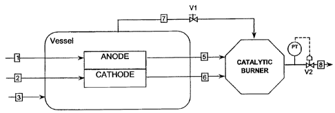
A pressurised fuel feed line 1 is connected to the anode
of the fuel cell stack. A pressurised oxidant feed line 2
is introduced into the cathode and inert gas (N2) air or
CA 02564888 2006-10-27
WO 2005/107003 PCT/EP2004/004779
11
other mixtures like cathodic exhaust is fed to the
containment vessel through line 3.
The system pressure is controlled by the valve V2
downstream of the catalytic burner, the pressure sensor
and pressure controller.
Valve V1, located on the vessel exhaust line, maintains
constant the required differential pressure between the
vessel and the fuel cell reactants in order to prevent
leakage of reactants to the vessel atmosphere.
In this case, the anode, the cathode and the vessel exits
are all at the same pressure, which is balanced and
equilibrated inside the catalytic burner that acts as
reference point. Anode and cathode pressures are always
equilibrated unless pressure drop occurs in the passage
trough the stack.
In this way there are no significant differential
pressure changes between anode-cathode and stack-vessel.
When that occurs, they are in a range of some mbar, even
if there is a failure on the cathode or anode stream.
The system is closely equilibrated and allows to minimise
the risks of differential pressure between electrodes and
between the fuel cell stack and the vessel.
CA 02564888 2006-10-27
WO 2005/107003 PCT/EP2004/004779
12
The vessel can be at room temperature or higher, the only
technical characteristic which has to be modified resides
in the valve V1, which can be "fail-open kind", with low
pressure drop, abounding or equipped with bypass in the
case of his casual shutting.
Furthermore, the valve located downstream of the
catalytic burner has an appropriate capacity to avoid the
pressure control loss or can be properly redounded.
In comparison with the separate pressure control on the
three streams (anode, cathode and vessel), this pressure
control device implies that the power plant can be
provided with a catalytic burner (CB) or other proper
mixing device allowing anode and cathode gas safe
mixing/burning where the exhausted gases are guided;
setting the valve Vl (or a calibrated orifice) the vessel
can be maintained at a slight overpressure on the stack
allowing intrinsic safe operation without gas leakage
from the stack to the containment vessel; the advantage
of a minimum number of control valves; the advantage of
an automatic pressure balance (an actual safety for the
stack); the advantages of a passive control system
without any component that could fail; in the case of
control system failure, the advantage that the system
temperature and pressure do not need to decrease to room
conditions.
CA 02564888 2006-10-27
WO 2005/107003 PCT/EP2004/004779
13
Another embodiment of the fuel stack system according to
the present invention is shown in Fig. 2.
Here two stacks 1 and 2 are fed by the lines 1-2 at the
cathode and by the lines 3-4 at the anode. In this
embodiment as well the stacks as the burner (B) are
contained inside the vessel 11.
The exhausted anodic gas is brought to the B by means of
the conducts 5 and 6. The exhausted cathodic gas is
introduced directly into the vessel (arrows 7 and 8) and
forms the covering atmosphere. By means of the outlet 10
a slightly low pressure is formed in the B, so that the
gas contained in the vessel is aspired inside the B
through the indicated openings.
Since the atmosphere in the vessel is constituted by the
cathodic gas containing oxygen, meets inside the B the
exhausted anodic gas containing hydrogen and the fuel not
reacted of the cell and the combustion occurs.
In this case too, the B constitutes the common element
for the cathodic and the anodic flow and the atmosphere
in the vessel, forming an equipotential point for the
pressures of these three parts.
The main differences with the previous embodiment are the
following ones:
CA 02564888 2006-10-27
WO 2005/107003 PCT/EP2004/004779
14
- one ore more stacks can be contained in the same
vessel
- one or more stack can be connected to the common
point
- the internal environment of the vessel is at high
temperature (-6500C)
- the internal atmosphere of the vessel is not inert
but contains diluted air
- the vessel is not fed independently but from the
cathodic gas itself.
- the B is placed inside the vessel
The overpressure condition of the vessel can be re-
established by means of the scheme in fig. 3, where the
vessel is fed with the same mixture of the cathodic
inlet. The cathodic and anodic outlets are both carried
to the B by means of conducts. The vessel is always in
conditions of overpressure over the stack(s).