Note: Descriptions are shown in the official language in which they were submitted.
CA 02565086 2006-10-30
WO 2005/116986 A1 PCT/EP2005/000478
DEVICE AND METHOD FOR AUTOMATIC TUNING OF A STRING INSTRUMENT, IN
PARTICULAR, A GUITAR
The present invention relates to a device for automatic tuning of a string
instrument
according to the preamble of Claim 1. It further relates to a method for
automatic tuning of a
string instrument according to the preamble of Claim 11.
In general, tuning instruments requires, in addition to a trained ear, a large
amount of
time, especially for untrained, for example, amateur instrumentalists. In the
classic method of
tuning "by hand," the musician works with a tuning fork, which gives a desired
tone when it is
struck, and the pitch of the relevant string is adjusted by changing the
string length or string
tension. By striking the string and the tuning fork several times, the result
is equalized until the
desired tuning of the string is achieved. Starting from this tuning, the other
strings are then tuned.
On the one hand, because the strings of the instrument always have to be tuned
regularly
due to an ever present elasticity of the material and, on the other hand,
because the strings are
also variable in length as a function of the climatic conditions (on the stage
of a concert hall, a
guitar string will expand with the heat and humid air in comparison with the
conditions in the
relatively dry and cool practice room), frequent tuning is necessary. Also,
after installing new
strings, these must be tuned.
To create a simplification here, in US 4,803,908 a device for automatic tuning
of a string
instrument was proposed, which has all of the features of the preamble of
Claim 1. In this device,
all of the strings are struck simultaneously on a guitar with an aid, which is
called "strummer" in
this publication and which is arranged in the body of the guitar. Electronics
detect the tones,
compare them with the desired setting, and control an adjustment device
engaging the strings for
adjusting the string tensions, such that they match the preset tones.
The system is very welcome to the extent that it allows easy and automatic
tuning and
takes away a large amount of work, especially for inexperienced musicians, and
also for
professionals. The system has a not insignificant disadvantage, however.
Overall it is large and
clumsy and requires considerable changes to the body of the guitar, which
affect, on the one
hand, the acoustics (sound) of the guitar and, on the other hand, the handling
of the guitar (due to
the changed weight). Apart from these characteristics, the appearance of the
guitar is also
changed not insignificantly.
Because the entire guitar forms the resonance body that is responsible for the
sound
characteristics, the sound characteristics also change when the body is
changed. Thus, the
CA 02565086 2006-10-30
previously known system is practically impossible to retrofit in existing
instruments, and it is
also difficult to integrate into new guitars. In particular, in terms of the
sound, two guitar types
were to be developed independently from each other in the design work, one
guitar with the
known device and one without.
The invention starts with the mentioned problems. The task of the invention is
to present
a device that is improved to the extent that it can be integrated into an
instrument, in particular, a
guitar, with minimal effect on the sound characteristics and with elements
that are as few and
small as possible. Furthermore, a method for automatic tuning of a string
instrument is to be
presented, which satisfies these conditions.
To accomplish this task, a device is proposed with the features of Claim 1. A
method that
accomplishes this task is given in Claim 11.
Claims 2-10 and 12-15 include advantageous improvements of the device and the
method, respectively.
The core concept of the invention is to feed the required power-supply voltage
to at least
parts of the components of the device via one or more of the strings. For this
purpose, the strings
have a conductive construction; they are composed of either a conductive
material or they are
wound and/or coated with such a material. In this way, for example, in a
guitar, in particular an
electric guitar, components can be arranged on the head of this guitar,
without also having to
integrate a power supply at this location (for example, in the form of a
battery or a separate
power-supply connection). In this example, the power-supply voltage can be fed
via the body of
the guitar and guided to the head via the one or more guitar string(s).
In this way, it is possible to arrange at least a few of the components of the
device in a
way that saves weight and space on a section of the instrument, which lies on
one longitudinal
end of the strings, on which there is either less space or which can support
less weight.
According to Claim 2, the components of the device (which, viewed as such, can
also be
called a system) are distributed on the instrument and a bus line bridges the
distance along the
length of the strings. In a guitar, for example, the entire device is not
arranged in the body. Thus,
the head or the neck also offers space, even if only a little, for
(unobtrusive) mounting of
additional components. In particular, the device can resort to using means
already arranged on
the head of guitars for adjusting the string length or tension, which reduces
the use of special
parts. Overall, in the instrument, for example, the guitar, fewer additional
components must be
installed.
The signal can be transmitted via the bus line, for example, via a
conventional bus cable,
and also in a wireless method, for example, via radio or infrared.
To be able to separate the control and drive components without far-reaching
intrusion
into the instrument body, however, according to an improvement of the
invention the control
CA 02565086 2006-10-30
3
signals are guided between the controller sitting on one instrument part and
the one or more
drives via the strings acting as bus lines (Claim 3). In many cases, the
strings of string
instruments are composed of a conductive material (metal) or are wound by a
thread made from
such a material. Alternatively, if the sound allows, they can be coated with a
conductive material.
This solution spares the use of additional lines that must be laid in the
instrument body. In this
way, in addition to the sound characteristics, not least of all the appearance
of the instrument is
maintained. If several strings are to be used as wires, to ensure that these
strings are not
electrically short-circuited to each other, elements guiding the strings
together (for example, the
bridge of a guitar) must be constructed so that they insulate the strings from
each other. For this
purpose, these elements can be fabricated from a non-conductive material (for
example, ceramic)
or can be coated with such a material or other precautions for insulation must
be taken (for
example, intermediate insulating disks, etc.).
The drive can be a motor, for example, an electric motor, but it can also
operate
pneumatically or hydraulically.
If the instrument is an instrument connected electrically to an amplifier
(e.g., an electric
guitar), then an already present pickup, which is connected to the amplifier
and which is part of
the instrument, can be used as (part of) the detection unit.
Through a construction of the controller as given in Claim 4, the controller
can be
activated in a simple way by striking one string.
An interface, as can be provided according to Claim 5, gives the ability to
feed software
into the device from the outside - also at a later time. Furthermore,
different reference tunings
can be input into the memory device via the interface, in order to be able to
tune the instrument
according to different tunings.
A construction of the device as proposed in Claim 6 allows string-by-string
tuning of the
instrument. A drive, which can be switched by means of corresponding gears or
similar devices
for adjusting each string, can also be used just as well.
If the device is formed as given in Claim 7, this produces an especially
compact
construction. If the individual components are selected to be as small as
possible, they practically
"disappear" into the overall appearance of the instrument and also do not
interfere with the
musician when he or she is playing. In addition, it is not necessary to attach
external components
for tuning the instrument. The musician can tune his instrument practically
anywhere and nearly
independently.
One improvement of the device according to Claim 8 produces a redundant
system. The
device can also continue to operate for tuning the instrument even if one
string is defective.
In each of Claims 9 and 10, a preferred construction of the device is given
for integration
into an electric guitar.
CA 02565086 2006-10-30
4
The method according to Claim 11 represents, as already stated above,
accomplishment
of the stated task in terms of a method. It can preferably be operated with a
device according to
one of Claims 1-10, but is not limited to such a device.
Claim 13 describes how the strings of the instrument can be preferably used as
bus lines.
In this way, separate cables or other transmission means (radio, infrared) do
not have to be
installed.
Processing of the first digital signal as required in an improvement of the
method
according to Claim 14 can be useful to be able to reliably determine a pitch
from this signal.
The base frequency (pitch) of the first digital signal is determined
preferably with the aid
of a mathematical frequency filter (Claim 15). In contrast to the otherwise
common method of
Fast Fourier Transformation (FFT), this filter allows a faster and more
precise frequency
determination from only one strike of a string. This is important, because
when a string is struck
only one time, the harmonics, which must be detected for an exact
determination of the pitch
(frequency), die away very quickly.
Below, the invention is described briefly with reference to the attached
figures. Shown
are:
Figure l, a schematic view of an electric guitar from the front as a possible
embodiment
of the invention,
Figure 2, a schematic view of the electric guitar from Figure 1 from behind,
Figure 3, another schematic view of the electric guitar with other details,
Figure 4, an enlarged representation of the body of the electric guitar
according to the
representation in Figure 3,
Figure 5, in four different representations (a)-(d), a saddle of the tremolo
system block of
the electric guitar,
Figure 6, schematically the attachment of the strings in the tremolo system
block, as well
as their contact with the power-supply lines or signal lines,
Figure 7, in four different views (a)-(d), the head of the guitar with
attached pegs and
actuators for setting the string tension,
Figure 8, in four different views, the pegs sitting in the head of the guitar
with the
servo-motors, and
Figure 9, a schematic circuit diagram of a detector circuit for controlling
tone-wire
feeding for the device for automatic tuning of the guitar.
In the figures, the invention is explained with reference to an embodiment for
an electric
guitar. Identical elements are provided with identical reference symbols in
the figures. The
description with reference to an electric guitar does not limit the invention.
It can be used just as
CA 02565086 2006-10-30
well for acoustic guitars, electric bass guitars, or other electric or
electric-acoustic or acoustic
string instruments, such as violins, harps, etc.
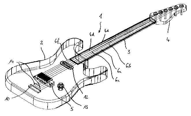
In Figures 1-4, an electric guitar l, which is provided with a device
according to the
invention, is shown in different, partially enlarged views. The electric
guitar 1 can be divided
roughly into the body 2, the neck 3, and the head 4. On the body, the strings
6a-6f are fixed with
their first ends (ball ends) to the so-called tremolo system block 5 and are
set in tension one next
to the other over the neck 3 up to the head 4, where they are wound on
adjuster devices 7 with
their second ends and can be adjusted. The adjuster devices 7 are connected
mechanically to
tuning pegs 8, so that by turning the tuning pegs 8, the string end on the
adjuster device 7 can be
wound onto this head or unwound from this head. In this way, the tension or
length of the string
is changed and the guitar is tuned.
In Figure l, a so-called pick guard 9 can also be seen, which is a kind of
covering plate
and under which, in the body 2, a space is created, in which the electronics
of the electric guitar 1
are arranged. Underneath this pick guard 9 there is a controller chip, which
is part of the device
according to the invention and which is indicated schematically with 10 in
Figure 2.
In Figure 2, it can also be seen that actuators 11 engaging with the mechanism
of the
tuning pegs 8, for example, by means of gears, are arranged on the head 4 of
the electric guitar 1.
The actuators belong to the device according to the invention and are
connected to the controller
chip 10 for control in a way still to be described below. As an alternative to
the hand operation
by means of the tuning pegs 8, the adjuster devices 7 can be turned with
motors and thus the
tension of the strings 6a-6f can be adjusted.
In Figures 3 and 4, the electric guitar 1 is shown in a different
representation. Here, in
addition to the elements to be seen in Figures 1 and 2, other details of the
electric guitar 1 are
shown. For example, the pickups 12 sitting on the body 2 underneath the
strings 6a-6f can be
seen, which convert the vibrations of the strings (and thus the tone generated
by striking these
strings) into an electric signal. These pickups 12 are simultaneously used in
a way still to be
described below as a component of the device according to the invention.
Furthermore, in these representations, a potentiometer 13 is shown. Usually,
electric
guitars provide several such potentiometers for setting the treble, bass, and
volume levels. Here,
the shown potentiometer 13 is the volume regulator. This special regulator is
not constructed as a
conventional potentiometer for integration of the device according to the
invention in the electric
guitar 1, but instead as a so-called push-pull potentiometer, which has an
additional switching
function.
Finally, still to be seen in these figures are the lines 14 leading from the
controller chip to
the tremolo system block 5, more precisely to the strings 6a-6f.
CA 02565086 2006-10-30
6
In Figures 5 and 6, the tremolo system block 5 and a saddle 15 arranged on
this block for
guiding the string ends fixed in the tremolo system block 5 are shown,
respectively. In Figure 6 it
can be seen how the strings 6a-6f are guided through bores 17 in the tremolo
system block 15
and are held at the bottom edge of the bores 17 with thick sections (ball
ends) 18 at their ends.
An insulating sleeve 19, which is provided on its edge projecting out of the
bore 17 with an
outwards pointing flange, is inserted into the bottom end of the bores 17.
Conductive disks 20,
which contact the thick sections (ball ends) 18 of the strings 6a-6f, are
positioned between the
flanges of the sleeves 19 and the thick sections (ball ends) 18. These disks
are connected, in turn,
with the lines 14 (shown here as 14a-14f) connected to the controller chip 10.
In this way, the strings 6a-6f of the electric guitar l, which are made from a
conductive
metal or are wound with a conductive metal thread, are connected electrically
to the controller
chip 10.
The saddles 15 shown in Figures 5(a)-5(d) are mounted on the tremolo system
block 5.
The strings run over these saddles in the region of the saddle inserts
designated with 16. The
saddle insert shown enlarged in Figure 5(d) is inserted into the saddle shown
in Figure 5(a) [by
insertion] into the recess shown on the right in Figure 5(a). Because the
saddle 15 and the saddle
inserts 16 in an electric guitar 1 are normally composed of metal and thus of
a conductive
material, the saddle inserts 16, over which the strings 6a-6f run, must be
insulated from each
other, in order to prevent a short circuit between the strings, which are
electrically contacted via
the lines 14. For this purpose, the surfaces designated with 21 in Figure 5(a)
are insulated.
In Figures 7(a)-7(d), details of the head 4 of the electric guitar 1 can be
seen again with
the attached components of the device according to the invention, with Figure
7(d) representing a
detail enlargement of the region designated with D in Figure 7(c).
In Figures 8(a)-8(d), the mechanical units for adjusting the string tension
are shown,
comprising the adjuster devices 7, the tuning pegs 8, and the actuators 11
disengaged from the
head 4. To be seen is that all of these units sit on a common circuit board
22, which contains
additional control elements for controlling the actuators 11. The strings are
connected electrically
to corresponding conductor tracks on the circuit board 22 via the metallic and
thus conductive
adjuster devices 7.
The device according to the invention for automatic tuning of the electric
guitar 1
operates as follows:
By pulling the push-pull potentiometer 13, the system is activated. Here,
refer to the
circuit shown in Figure 9, which will be described below.
Commands can now be issued to the controller chip 10 by striking one of the
strings. The
tones generated by striking the strings are converted by the pickups 12 into
an electric signal,
which is converted to a frequency in the controller. Defined pre-programmed
commands, which
CA 02565086 2006-10-30
7
are called at a frequency lying within a certain tolerance, are stored in the
controller. In this way,
for example, the program for tuning one of the strings, e.g., the e-string 6f,
can be called. If the
program is activated, then the controller chip loads a reference frequency for
this string, which is
used as a desired frequency, from a memory. The string is now optionally
struck again, the actual
frequency is calculated from the signal converted by the pickup 12 in the
controller chip 10, and
a signal is sent to the circuit board 22 or via this circuit board to the
corresponding actuator 11
via the strings used as bus lines for adjusting the string tension for
reaching the desired
frequency. Here, the controller chip 10 monitors the change in frequency and
outputs a stop
signal to the actuator 11 when the desired frequency is reached. In this way,
all of the strings can
be tuned one after the other. A mathematical frequency filter is used as the
routine for calculating
the actual frequency from the electric signal of the pickups, because this can
calculate the
frequency especially quickly and reliably.
By means of an interface not shown in the figures, different frequency
defaults for the
strings can be given to the controller chip 10 according to which type of
tuning has currently
been selected (for example, open tuning, etc.).
For transmitting the control signals, only two of the strings are needed. By
means of two
other strings, here the strings 6f (low e-string) and 6e (a-string), the power
supply for the circuit
board 22 and the actuators 11 is brought to the head 4, so that a separate
power source is not
necessary there. The strings 6f and 6e are selected for transmitting the
voltage, because the low
e-string and the a-string are the thickest strings of the electric guitar 1
and thus very rarely break.
Of the remaining four strings 6a-6d, any two can be freely controlled by the
controller chip 10 as
bus lines. In this way, the system is redundant and can still operate if one
or even if two of the
strings 6a-6d break.
Light-emitting diodes on the body 2, for example, in the area of the pickups
12
underneath the strings 6a-6f can display the state of the controller chip 10
or the program
sequence and thus simplify the handling of the device. Here, "brief
instructions" can also be
displayed, e.g., with the display, by striking which of the strings 6a-6f in
which tone which
commands are called. The frequencies allocated to the commands can be managed
by the
controller chip 10, so that they are adapted to the current tuning of the
electric guitar, that is, the
user must always strike the same string with the same grip in order to call a
command, regardless
of how the guitar and thus the string has just been tuned.
In this embodiment, the power supply for the system is realized externally,
that is, via the
amplifier cable, with which the guitar is already connected electrically to an
amplifier. The tone
wire circuit shown in Figure 9 constantly monitors the internal resistance of
the electric guitar 1.
For normal, ready-to-play electric guitars 1, this resistance is high. If the
musician now pulls the
push-pull potentiometer 13, then this decouples the pickup 12 from the jack
socket for the
CA 02565086 2006-10-30
g
amplifier cable and thus from the amplifier and activates the controller chip
10. In this way, the
internal resistance of the electric guitar 1 decreases by a factor of at least
20. This circuit detects
this condition and disconnects the amplifier cable, for one, from the
amplifier, so that the electric
guitar 1 can be tuned in a "muted" state. Furthermore, the circuit switches a
power-supply
voltage onto the amplifier cable, which can be obtained, for example, from the
power-supply part
of the amplifier and also from an external power-supply part. This voltage is
then fed to the
controller 10 and forwarded into the head 4 via the strings 6e and 6f. Now the
device according
to the invention can function. After the tuning is complete or, for example,
the circuit is installed
or new data is entered, the musician switches the push-pull potentiometer 13
back into the
normal position. The internal resistance of the electric guitar 1 increases
through the pickup 12
now connected again to the amplifier cable. The tone wire circuit detects this
according to Figure
9 and outputs the signals from the amplifier cable back to the amplifier, so
that the musician can
continue to play.
List
of
reference
symbols
1 Electric guitar
2 Body
3 Neck
4 Head
Tremolo system
block
6a-fString
7 Adjuster device
8 Tuning peg
9 Pick guard
Controller chip
11 Actuator
12 Pickup
13 Potentiometer
14 Line
Saddle
16 Saddle insert
17 Bore
18 Thick section
19 Sleeve
Disk
<IMG>