Note: Descriptions are shown in the official language in which they were submitted.
CA 02565139 2006-10-31
WO 2005/106086 PCT/N02005/000146
1
Production of carbon nanotubes
This invention relates to production of carbon nanotubes, more specific the
invention relates to improvements in the arc discharge method for producing
high
quality multi-walled carbon nanotubes (M)VNT).
Background
Carbon nanotubes are very long and closed tubular structures that may be
considered to be a graphitic sheet that is folded onto itself to forin a
seamless
cylinder which is terminated in both ends by a fiillerene-like hemisphere.
Carbon
nanotubes are unique nanostructures that conceptually can be considered as a
one-
dimensional quantum wire due to their narrow size and very huge aspect ratio.
The simplest form of nanotubes is the single walled nanotube (SWNT), which is
one
atom in wall thickness and typically tens of atoms around the circumference.
There
are also known multi walled structures where two or more stacked graphitic
sheets
are folded onto themselves to form two or more concentric nanotubes similar to
the
Russian doll structure. This multi-walled structure is often denoted as a
multi-
walled carbon nanotube (MWNT).
After the discovery of carbon nanotubes in 1991, it was realised that carbon
nanotubes may be considered as the ultimate carbon fibre formed of perfectly
graphitized closed seamless shells which show unique mechanical and electronic
properties that are very sensitive to its geometry and dimensions [1]. A
decade later
extensive research activity has established that carbon nanotubes is almost
certainly
the strongest, stiffest, and toughest molecule that can ever be produced, the
best
possible molecular conductor of both heat and electricity. In one sense the
carbon
nanotube is a new man-made polymer to follow from nylon, polypropylene and
Kevlar. In another, it is a new "graphite" fibre, but now with the ultimate
possible
strength. In yet another it is a new species in organic chemistry, and
potentially in
molecular biology as well, a carbon molecule with the almost alien property of
electrical conductivity, and super steel-strength [2].
Thus the potential of the carbon nanotube in the inaterial, chemical and
physical
sciences and in several industrial fields is obviously vast. It is therefore
an immense
expectation and research activity in the world today for developing new
materials,
applications and products involving carbon nanotubes in a variety of fields
such as
reinforcement material for composites, ceramics, and metals, as conductive
component in composites, as battery electrodes, as energy storage medium, in
semi-
conducting applications such as cathode-ray lighting elements, flat panel
displays,
gas-discharge tubes for telecom, as nanoprobes and sensors, etc.
However, there is especially one obstacle that must be solved before carbon
nanotubes can become a widely used industrial material; to date there are no
known
CA 02565139 2006-10-31
WO 2005/106086 PCT/N02005/000146
2
production methods that have successfully been scaled up to those mass
production
levels needed to bring the production costs of such nanotubes down to cost
levels
that the consumer marked can digest. Thus, so far, carbon nanotubes have only
found use in high-technological niche products optimised on functionality and
other
applications where price is of little issue. If the potential of the very
promising
properties of carbon nanotubes shall be realised in typically consumer
products such
as clothes, electronic devices, batteries etc., the production costs must be
cut
substantially from present levels. This is especially the case for those
qualities of
MWNTs that this application is related to.
Prior art
It was discovered in 1992 that an arc discharge method used for production of
carbon whiskers could be modified to produce high quality MWNTs. This method
is
thoroughly described in pages 140 - 148 in [1] and is included in its entirety
by
reference in this application. This method and apparatus will be denoted as
the
conventional arc discharge method in this application.
The conventional arc discharge method employs plasma, formed in helium gas
when passing high DC currents through an opposing anode and cathode (in the
form
of carbon rods) in a helium atmosphere, to evaporate carbon atoms of the anode
that
subsequently condenses on the cathode to form MWNTs and other carbon
structures. In this way, the carbon anode is gradually consumed and the
deposit
grows accordingly on the cathode. The deposit will obtain the saine shape as
the
anode. If for instance a longitudinal hole is drilled at the centre of the
anode, the
deposit will also have such a hole.
Due to the high teinperatures needed to evaporate carbon, the process inust.be
performed in an inert atmosphere, and it is typically employed.a helium
atmosphere
of approximately 500 Torr, typical current densities are about 150 A/cm2
(cross
section area of the anode), applied voltage is around 20 V, the distance
between the
anode and cathode is about 1 mm, the diameter of the anode is in the order of
5-10
mm, and the cylindrical growth rate of the deposit will be in the order of 1-2
min/min. The temperatures in the plasma zone are typically in the order of
3000-
4000 C.
From experience it seems that a careful control of the current during the
process is
necessary. Too inuch current will fuse the material into a useless solid while
a too
little current will result in a slow deposit rate. The challenge is therefore
to maintain
a medium current flow as steady as possible. Experience has also shown that
the
cathode should be effectively cooled in order to obtain the best conditions
for
condensation of carbon nanotubes. Typically, the deposit on the cathode will
be a
cylinder rod with an outer hard shell of fused and useless material (nanotubes
and
nanoparticles fused together), and a black fibrous core containing about two-
thirds
CA 02565139 2006-10-31
WO 2005/106086 PCT/N02005/000146
3
nanotubes and one-third nanoparticles (polyhedral graphitic particles, also
known as
carbon onions).
A long standing problem with this arc discharge technology has been the
relatively
slow deposition rates of 1-2 inm/min and the relatively narrow diaineters of
the
carbon anodes of a few mm. Thus the production rates are too small to make
this
method viable for mass production of carbon nanotubes for the consumer market.
Even though one can envision large series of plasma reactors such that the
total
output may be many kilograms per minute, the investment and maintenance costs
will be too heavy to bring the production costs to levels which will allow
nanotubes
to replace traditional carbon fibres in consumer products such as plastics,
composites, electronic devices etc. Therefore, if the carbon nanotube is to
substitute
far cheaper carbon fibres, the production capacity of each plasma reactor
should be
substantially enhanced from present levels. And since the temperature
dependency
of the formation process of the nanotubes makes it hard, if not impossible, to
sufficiently increase the deposition rates to meet this objective, the only
option is to
increase the diameters of the carbon anodes.
However, the scaling up of the anode is complicated by a major problem: The
current densities flowing through the electrodes decreases when the diaineter
of the
electrodes is increased, resulting in substantially lowered deposition rates
and
wrong characteristics of the formed deposit.
Another problem encountered when using wider electrodes is that the plasma
tends
to be irregular such that the control of the gap between the electrodes is
probably
the most critical point of the process. It has been observed that the
electrodes tips
do not remain smooth and flat during the discharge. As the nanotube deposition
proceeds, the tip surfaces change continuously in an erratic way. Nanotube
deposition occurs preferentially in some parts of the cathode while the facing
parts
of the anode are excessively consumed. It is therefore important to find a way
to
maintain the electrode tips as even as possible. The inventors have observed
that
rotating the electrodes in relation to each other gives only a partial
solution to the
problem, since the rotation only works for maintaining the anode surface
relatively
flat. The irregularities of the cathode deposit tend, on the other hand, to be
amplified. This problem will be enhanced with increasing diameters, and need
to be
solved.
Objective of the invention
The main objective of this invention is therefore to provide a method and
apparatus
based on the conventional arc discharge technology that allows use of
electrodes
with large diazneters for production of high-quality MWNTs.
CA 02565139 2006-10-31
WO 2005/106086 PCT/N02005/000146
4
It is also an objective of this invention to provide a method based on the
conventional arc discharge technology that gives an iinproved control with the
temperature gradients in the electrodes in order to allow use of large
electrode
diameters and reduced current densities.
Summary of the invention
The objectives of the invention can be obtained by the features as defined in
the
appended claims and following description of the invention.
The invention is based on a discovery that the electric conductivity of carbon
decreases at temperatures approaching the vaporization point, and that this
causes
an enhanced resistance at the lower section near the tip of the anode due to
heat
conducted from the vaporization zone and into the bulk material of the anode.
This
problem is expected to become more severe with larger diameters of the
electrodes,
probably because a smaller fraction of the heat energy from the vaporization
zone in
the gap between the anode and cathode can escape by heat radiation since
electrode
tips with larger surface areas will absorb a larger fraction of the heat
generated by
the plasma inside the gap. Also, the heat generated within the electrodes by
the flow
of current i-s mainly dissipated via radiation. Thus, due to a decreasing
surface/-
volume ratio with increased diameters, it should be expected that this
dissipation
becomes less efficient for higher diaineters.
Thus according to this invention, the problem with increased electric
resistance in
the anode can be solved or at least substantially reduced by providing cooling
ineans that controls/lowers the temperature in the anode at its lower parts
facing the
cathode. By lower part we mean the end section of the anode rod that is not
connected to the base, i.e. the tip or lower section facing the cathode. This
anode
cooling should not be confused with conventional cooling of the electrodes
where
the bases of the electrodes are equipped with water cooling devices. Cooling
of the
base will of course not provide a satisfactory control of the temperature at
the
opposite end of the anode rod due to an insufficient thermal contact between
the tip
of the anode and the cooling device at the base.
In a preferred embodiment of the invention, the water cooling of the lower
section
of the anode is provided by placing an annulus shaped water-cooled copper
block
around the lower section of the anode, see figure 2. By lower section we mean
in
the opposite end of the base, that is, the end section comprising the tip of
the anode.
The copper block has a through-going centre hole with an inner diaineter that
is
slightly larger than the outer diaineter of the anode, and the anode rod is
inserted
coaxially from above at the centre of this through-going hole and lowered
until the
tip protrudes slightly below the bottom plane of the copper block. This
position
must of course be maintained by lowering the anode electrode in accordance
with
the rate at which it is being consuined during production. The inventive idea
of
CA 02565139 2006-10-31
WO 2005/106086 PCT/N02005/000146
providing cooling of the anode tip in order to obtain better control with the
teinperature in this section of the anode can is of course not liinited to the
use of
water-cooled copper blocks, but may be implemented with any other conceivable
cooling device known to a skilled person.
5 The use of the water-cooled copper block has been tested on electrodes with
a
diameter of 25 inm. In accordance with the assuinption that very high
temperatures
increases the electric conductivity resistance in the anode, an improved
control with
the current flow with much less current drop was obtained by applying active
cooling of the lower section of the anode, shoving that it is possible to
increase the
production rates in each reactor by increasing the diameter of the electrodes.
It is
also found that the teinperature in the chamber during the process is much
lower
with the cooling block, and thus the thermal wear on reactor components will
be
reduced accordingly.
There have also been found some unexpected beneficial results when applying
the
invention. For example has it been observed that the anode remains relatively
flat
during the process, even if the electrodes are not rotated in relation to each
other
when the temperature of the tip of the anode is lowered due to active cooling.
This
observation may be explained by the fact that the current distribution in the
anode is
probably more hoinogenous when the anode is cooled because the therinal
gradients
are reduced. Cooling the anode tip appears as an alternative solution to keep
its
surface flat. Another unexpected advantage of the inventive cooling is that
the soot
production is reduced by a factor of 2 compared to prior arts without such
cooling.
This is an especially advantageous result since it contributes to increase the
yield to
a greater extent than what is expected form the pure enhancement of the
diameter of
the electrodes.
The invention should not be considered to be restricted to electrodes with
diameters
of about 10-25 mm, but can of course be applied to any conceivable diameter of
the
electrodes up to diameters of several meters in magnitude.
Another problem with employing electrodes with larger diameters is the
initiating of
the arc and maintaining an even burn rate and thus, an even shape of the anode
tip.
The inventors have discovered that this problem can be solved or at least
substantially reduced by providing a narrowing of the anode tip. In this way,
the
contact surface between the two electrodes during the initial contact is
significantly
reduced, and the current is forced to pass through a very restricted area such
that the
current flowing through the electrodes is considerably diminished. At the
contact
point, the high current density (i.e. the current/section ratio) induces
locally an
iinportant increase of the temperature and the pointed end is rapidly
vaporized.
Using this method, it is therefore possible to start with relatively flat
electrodes.
CA 02565139 2006-10-31
WO 2005/106086 PCT/N02005/000146
6
The size of the pointed end should be fitted according to the diameter of the
electrodes. If the diameter of the point is too small, the current flowing
through the
electrodes during the contact will not be enough to sufficiently increase the
temperature of the electrodes and the arc will extinguish as soon as the
pointed end
is consuined. An example of a preferred fitting in the case of 12 mm diameter
electrodes is a tip with length 1 mm and diameter of 2.5 mm. In general, the
diameter of the pointed end should be within in the range froin 1/2 to 1/8 of
the
diameter of the anode.
A further problem when working with larger diameters is that the control of
the gap
becomes more iinportant. Experiments have demonstrated that the best
conditions
for the production of nanotube material coincide with an average gap of 1-3 mm
between the electrodes but gaps up to 12 mm can be used provided some
precautions are taken (see below). It has been observed that the thickness of
the
hard outer shell (that does not contain nanotubes) is sigriificantly reduced
when
using such large gaps. This suggests that the temperature of the cathode
deposit may
be lower when increasing the gap between the electrodes. However, the major
drawback of this method is that the nanotube production rate is also
considerably
decreased.
Maintaining a large gap is therefore not pertinent when working with up to 12
mm
diameter electrodes but might be necessary with larger ejectrodes, especially
if heat
dissipation from the plasma turns out to be a major problem. Another advantage
of
using large gaps is that no sophisticated system for the control of the
electrodes
motion is required. The gap can simply be adjusted by monitoring the current
and
maintaining it constant. However, the gap must be increased very gradually.
The
reason is that the current drops rapidly when the distance between the
electrodes
exceed approximately 3-4 mm. To counterbalance the decrease in current, the
voltage must therefore be gradually increased as the gap is augmented.
As a precaution, it is better to wait for 1-2 minutes after the discharge has
been
initiated before augmenting the gap. A preinature increase of the gap
frequently
leads to the arc extinction, probably because it has not stabilised yet.
The inventive features of applying active cooling of the lower sections of the
anode
tip and providing a,narrowing of the tip may be implemented on all known
conventional arc discharge reactors for producing carbon nanotubes with a
device
for cooling the anode tip in order to maintain a better control of the
temperature and
current flow. By conventional arc discharge reactors we mean reactors as
described
in the prior art section above where two carbon electrodes are opposing each
other
with a narrow gap between them in an inert atmosphere. One example of such
reactors are presented on page 143 of [1], one other is given in figure 2 of
[4].
Usually, each'electrode will be inounted on rotatable water-cooled bases such
that it
CA 02565139 2006-10-31
WO 2005/106086 PCT/N02005/000146
7
is possible to rotate the electrodes in relation to each other. The size of
the gap
between the opposing electrode tips can be strictly controlled and adjusted in
order
to maintain the optimum voltage drop over the gap, and thus controlling the
current
density through the electrodes. When a suitable DC-potential is applied at
these
bases, a DC-current will flow through the electrodes and cross the gap between
them to forin plasma. This plasma will heat the tip of the anode to an extent
which
causes carbon atoms to evaporate and migrate to the water-cooled cathode and
deposit there. Such reactors are well known to the skilled person and need no
further description here. By larger diameters of the electrodes we mean from
about
10 inm in diameter and every practically conceivable size above 10 mm.
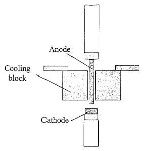
List of figures
Fig. 1 shows a schematic drawing of a prior art conventional arc discharge
reactor
according to [4]
Fig. 2 shows a cross-sectional view from the side of the anode provided with a
water-cooled copper block according to a preferred embodiment of the
invention.
Fig. 3 shows a cross-sectional view from the side of anode according to the
invention and the initiating of the arc.
Fig. 4 shows a diagram presenting the current through the anode as a function
of
time with no cooling of the anode.
Fig. 5 shows a diagram presenting the current through the anode as a function
of
time with active cooling of the anode according to the invention.
Verification of the invention
The invention will now be described in larger detail by way 'of verification
experiments performed on a preferred embodiment of the invention.
The first series of verification tests was performed in order to test the
assuinption
that the electrical conductivity of carbon decreases at higher temperatures,
such that
it is ,the temperature of the anode tip that is the limiting factor on the
current
through the electrodes.
1 st series of experiments:
The anode was wrapped in a graphite foil in order to increase its thermal
insulation.
The graphite foil was maintained in contact with the anode by means of several
rings of graphite felt stacked on top of each other (see Figure 3), which also
helped
to improve the anode insulation. On purpose, the tip of the anode was left
non-insulated.
CA 02565139 2006-10-31
WO 2005/106086 PCT/N02005/000146
8
The current with a non-insulated 12 mm diaineter anode is usually ranging from
180 to 200 A. In the present case, a very similar current was measured
initially.
However, a significant current drop was observed as soon as the distance from
the
tip to the insulated part of the electrode becaine lower than - 1.5 cm. The
experiment was stopped when the tip of the anode went out of sight. At that
time,
the current had dropped down to 120 A (figure 4). The most plausible
explanation is
that the current drop is correlated to an increase of the anode tip
temperatu're as the
distance between the tip and the insulated part gets smaller.
2"d series of experiments:
In order to confirin the assumption of decreasing electrical conductivity at
high
temperatures, a complementary set of experiments was performed using a
different
configuration designed to reduce the temperature of the anode tip. The
experiments
were perforined with very short anodes. (The electrodes are mounted on water-
cooled copper holders. By reducing the length of the anode, it is possible to
improve
the cooling of the tip and, therefore, to reduce its temperature). Three
experiments
were performed on 26 mm diaineter electrodes with increasingly shorter lengths
(respectively 2.5, 1.5 and 1 cm). As expected, the current was observed to
increase
when decreasing the ariode length, see figure 5. This result show that an
increase of
the temperature at the carbon anode tip leads to a decrease of the current
flowing
through it.
References
1 Ebbesen, T. W. (ed.), "Carbon Nanotubes, preparation and properties",
CRC Press Inc. 1997, preface.
2 Dresselhaus M.S. et al. (ed.), "Carbon Nanotubes, synthesis, structure,
properties and applications", Springer Verlag, Topics in Applied Physics,
Vol 80, foreword by Richard E. Smalley.
3 Ebbesen, T. W. and Ajayan, P. M., Nature 358, 1992, 220-222.
4 Colbert, D.T. et al., "Growth and Sintering of Fullerene Nanotubes",
Science, vol. 266, 1994.