Language selection

Search

Patent 2565212 Summary

Third-party information liability

Some of the information on this Web page has been provided by external sources. The Government of Canada is not responsible for the accuracy, reliability or currency of the information supplied by external sources. Users wishing to rely upon this information should consult directly with the source of the information. Content provided by external sources is not subject to official languages, privacy and accessibility requirements.

Claims and Abstract availability

Any discrepancies in the text and image of the Claims and Abstract are due to differing posting times. Text of the Claims and Abstract are posted:

  • At the time the application is open to public inspection;
  • At the time of issue of the patent (grant).
(12) Patent: (11) CA 2565212
(54) English Title: COOLED INSTRUMENT PANEL COMPARTMENT FOR A VEHICLE
(54) French Title: COMPARTIMENT DE TABLEAU DE BORD FRIGORIFIE POUR VEHICULE
Status: Granted
Bibliographic Data
(51) International Patent Classification (IPC):
  • B60R 7/06 (2006.01)
  • B60H 1/32 (2006.01)
(72) Inventors :
  • KUKUCKA, RICHARD (United States of America)
  • OZARK, L. JOHN, JR. (United States of America)
  • JEZUIT, JOHN (United States of America)
  • MARGINEAN, CALIN (United States of America)
  • DUBIEL, ROBERT (United States of America)
  • GODSHALL, JEFFREY I. (United States of America)
  • NAGODE, RYAN C. (United States of America)
(73) Owners :
  • CHRYSLER GROUP LLC (United States of America)
(71) Applicants :
  • DAIMLERCHRYSLER CORPORATION (United States of America)
(74) Agent: BLAKE, CASSELS & GRAYDON LLP
(74) Associate agent:
(45) Issued: 2014-02-25
(22) Filed Date: 2006-10-23
(41) Open to Public Inspection: 2007-05-04
Examination requested: 2011-06-28
Availability of licence: N/A
(25) Language of filing: English

Patent Cooperation Treaty (PCT): No

(30) Application Priority Data:
Application No. Country/Territory Date
11/267,690 United States of America 2005-11-04

Abstracts

English Abstract

A glove box assembly for a vehicle is provided. The glove box assembly includes a storage bin and a dedicated climate controlled bin. The climate controlled bin is arranged to receive cooled air from a vehicle heating, ventilation and air conditioning (HVAC) unit for cooling the climate controlled bin independent of the storage bin. The glove box assembly further includes a cooled air inlet. The cooled air inlet is arranged to draw cooled air from the HVAC unit upstream of a blend door when air conditioning is operating so as to provide cooled air to the climate controlled bin independent of a vehicle cabin temperature setting.


French Abstract

Une boîte à gants pour véhicule est présentée. La boîte à gants comprend un compartiment de rangement et un compartiment dédié à température contrôlée. Le compartiment à température contrôlée est conçu pour recevoir l'air refroidi d'un système de chauffage, ventilation et conditionnement de l'air (CVCA) de véhicule pour refroidir le compartiment à température contrôlée indépendamment du compartiment de rangement. La boîte à gants comprend également une prise d'entrée d'air refroidi. La prise d'entrée d'air refroidi est conçue pour attirer l'air refroidi du module CVCA vers l'amont d'une porte de mélange lorsque le conditionnement de l'air est en marche de sorte à fournir de l'air refroidi au compartiment à température contrôlée indépendamment de la température de la cabine du véhicule.

Claims

Note: Claims are shown in the official language in which they were submitted.

CLAIMS

What is claimed is:
1. A glove box and heating, ventilation, and air conditioning unit assembly
for use in
a vehicle, the glove box including a storage bin, a climate controlled bin,
and a cooled
air inlet arranged to receive cooled air from the vehicle heating,
ventilation, and air
conditioning unit, the heating, ventilation, and air conditioning unit
including an
evaporator operable to cool a first air stream, a heater core operable to heat
a second
air stream, a blend air door in fluid communication with and disposed between
said
evaporator and said heater, whereby:
said cooled air inlet of the climate controlled bin is connected to said
heating,
ventilating, and air conditioning unit by a conduit having an intake
downstream of said
evaporator and upstream of said blend air door whereby so long as the air
conditioning
unit is on, said conduit receives cooled air regardless of any warm air from
the heater
core, the warm air being blended via the blend air door to achieve a desired
cabin
temperature setting, and whereby:
the downstream end of said conduit is coupled to said climate controlled bin
to deliver
cooled air to said climate controlled bin independently of said storage bin.
2. The glove box and heating, ventilation, and air conditioning unit
assembly
according to claim 1, characterized in that the glove box is closeable by a
door arranged

7

to pivot between an open position providing access to the storage bin and the
climate
controlled bin and a closed position in which the storage bin and climate
controlled bin
are closed.
3. The glove box and heating, ventilation, and air conditioning unit
assembly
according to claim 2, characterized in that a seal is positioned on an outer
perimeter of
the climate controlled bin and arranged to engage the door in the closed
position
providing a thermal barrier for cooled air contained within an enclosed volume
of the
climate controlled bin.
4. The glove box and heating, ventilation, and air conditioning unit
assembly
according to claim 3, characterized in that seal is positioned on the door and
arranged
to engage an outer perimeter of the glove box to seal the bin and provide a
thermal
barrier for cooled air contained within an enclosed volume of the climate
controlled bin.
5. The glove box and heating, ventilation, and air conditioning unit
assembly
according to any one of claims 1 to 4, characterized in that the glove box
further
includes a removable liner,

8

6. The glove box and heating, ventilation, and air conditioning unit
assembly
according to claim 5, characterized in that the liner is contoured to support
at least one
beverage container and prevent said container from rolling during vehicle
operation.
7. The glove box and heating, ventilation, and air conditioning unit
assembly
according to claim 6, characterized in that the contour of the liner defines a
plurality of
scallops arranged to support a plurality of beverage containers.
8. The glove box and heating, ventilation, and air conditioning unit
assembly
according to claim 2, characterized in that the climate controlled bin further
includes an
internal door arrangement operable selectively to block a flow of cooled air
from the
vehicle heating, ventilating, and air conditioning unit.

9

Description

Note: Descriptions are shown in the official language in which they were submitted.


CA 02565212 2006-10-23

COOLED INSTRUMENT PANEL COMPARTMENT FOR A VEHICLE
The present invention relates generally to a cooled instrument panel
compartment for a vehicle.

Motor vehicles today are used for many purposes including commuting
and trips of long duration. During such trips, for example, vehicle occupants
often bring food and chilled beverages for consumption and such beverages are
typically placed in various cup holders provided in today's vehicles. One
disadvantage of the typical cup holders is that the chilled beverages often
warm

up to ambient vehicle temperature before or during their consumption. To
counteract this disadvantage, a cooler is sometimes used by vehicle occupants
to keep their beverages cool before consumption. Using such a cooler however,
requires using vehicle space that could be used by an occupant or placing the
cooler in a vehicle.


Thus, there is a need for a cooled instrument panel compartment that
overcomes the aforementioned and other disadvantages.

Accordingly, a cooled instrument panel compartment for a vehicle is
provided. In accordance with one aspect of the present invention, a glove box


CA 02565212 2006-10-23

assembly is provided and includes a storage bin and a dedicated climate
controlled bin. The climate controlled bin is arranged to receive cooled air
from a
vehicle heating, ventilation and air conditioning (HVAC) unit for cooling the
climate controlled bin independent of the storage bin.


In accordance with one aspect of the present invention, the glove box
assembly includes a cooled air inlet. The cooled air inlet is arranged to draw
cooled air from the HVAC unit upstream of a blend door when air conditioning
is
operating so as to provide cooled air to the climate controlled bin
independent of
io a vehicle cabin temperature setting.

Other aspects, features, and advantages of the present invention will
become more fully apparent from the following detailed description of the
preferred embodiment, the appended claims, and in the accompanying drawings
in which:

Figure 1 illustrates a vehicle glove box assembly having a dedicated
climate controlled bin in accordance with the present invention;

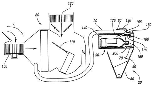
Figure 2 illustrates a simplified view of a HVAC assembly interacting with
the dedicated climate controlled bin of the glove box assembly in accordance
with the present invention; and

2


CA 02565212 2006-10-23

Figure 3 illustrates a partial front view of the dedicated climate control bin
having a removable liner in accordance with the present invention.

In the following description, several well-known features of an instrument
panel and glove box are not shown or described so as not to obscure the
present
invention. Referring now to the drawings, Figures 1 - 3 illustrate an
exemplary
embodiment of a glove box assembly 10 incorporated into an instrument panel
module 20 in accordance with the present invention.


Glove box assembly 10 includes a door 30 arranged to pivot between a
closed position and an open position as best shown in Figures 1 and 2. In the
open position, door 30 provides access to a storage bin 40 and a dedicated
climate controlled bin 50. The climate controlled bin 50 is a separate bin and
functions independently from storage bin 40.

The dedicated climate controlled bin 50 has a rectangular shape and is
arranged to interact with a vehicle HVAC system 60 (Figure 2) to provide
selective cooled air to the climate controlled bin 50 while not cooling the
storage

2o bin 40. The climate controlled bin 50 includes a seal 70 positioned on an
outer
perimeter of the bin and arranged to engage door 30 when door 30 is in a
closed
position. Alternatively, seal 70 could be positioned on door 30 so as to
engage
3


CA 02565212 2006-10-23

the outer perimeter of climate controlled bin 50 when door 30 is in the closed
position.

As best shown in Figure 2, the dedicated climate controlled bin includes
an air inlet 80 arranged to be connected to a hose 90 that is connected to
HVAC
system 60 for providing the climate controlled bin with selective cooled air
from
HVAC system 60. Hose 90 is connected to HVAC system 60 down stream of an
evaporator 100, but upstream of a blend air door 110 so as to provide cooled
air
to the dedicated climate controlled bin 50 when an air conditioning (AC)
system

io is on regardless of a vehicle cabin temperature setting. More specifically,
by
placing hose 90 upstream of blend air door 110 and thus heater core 120, so
long as the AC is on, hose 90 receives cooled air regardless of any warm air
from the heater core 120 that is blended via the blend air door 110 to achieve
a
desired cabin temperature setting.


Air inlet 80 directs cooled air into an upper portion 130 of the dedicated
climate controlled bin 50. Upper portion 130 is separated from a lower portion
140 by an internal, adjustable air vent arrangement 150. The internal venting
arrangement 150 includes a perforated panel 160 fixed to climate controlled
bin

2o 50 and a translatable perforated panel 170 arranged to cooperate with fixed
perforated panel 160 to open or block cooled air from upper portion 130 to
lower
portion 140. More specifically, translatable panel 170 is arranged to slide so
as
4


CA 02565212 2006-10-23

to align perforations 165 and 175 of panels 160 and 170, respectively, and
thus
allow cooled air into lower portion 140 and thus cool any contents of the
dedicated climate controlled bin 50, or to have the perforations 175 of
translatable panel 170 not align with the perforations 165 of fixed panel 160
so

as to block off cooled air from upper portion 130 and not cool the dedicated
climate controlled bin 50. A vehicle operator can translate panel 170 via a
handle arrangement, such as handle 180 shown in Figures 1 and 2.

The climate controlled bin 50 also includes a removable liner 200.
io Removable liner 200 can comprise many configurations depending on what type
of contents are desired to be cooled in the climate controlled bin. In this
exemplary embodiment, removable liner 200 includes four scallops 210 arranged
to receive beverage containers and prevent the containers from rolling in the
dedicated climate controlled bin 50 as best shown in Figure 3. Scallops 210
are

sized such that typical beverage containers such as a 12 ounce can or a 20
ounce plastic bottle are held in place and up to four or either container can
be
easily placed and cooled in the dedicated climate controlled bin 50.

In operation, the dedicated climate controlled bin effectively provides a
2o built in cooler for a vehicle that is incorporated into a glove box
assembly while
remaining independent from a storage area of the glove box assembly. With the
dedicated climate controlled bin, a vehicle occupant can continue to use the
5


CA 02565212 2006-10-23

storage area of the glove box while also being able to selectively cool
desired
items in a separate bin independent from the glove box storage area which will
not receive the cooled air.

The vehicle occupant can also cool desired items in the dedicated climate
controlled bin with the AC on regardless of a desired vehicle cabin
temperature.
Thus, even if a vehicle occupant selects a cabin temperature that requires
blending warm air with air conditioned air, the dedicated climate controlled
bin
will only receive cooled air from the HVAC unit because the dedicated climate
io controlled bin receives the cooled air from upstream of the blend air door.

6

Representative Drawing
A single figure which represents the drawing illustrating the invention.
Administrative Status

For a clearer understanding of the status of the application/patent presented on this page, the site Disclaimer , as well as the definitions for Patent , Administrative Status , Maintenance Fee  and Payment History  should be consulted.

Administrative Status

Title Date
Forecasted Issue Date 2014-02-25
(22) Filed 2006-10-23
(41) Open to Public Inspection 2007-05-04
Examination Requested 2011-06-28
(45) Issued 2014-02-25

Abandonment History

There is no abandonment history.

Maintenance Fee

Last Payment of $459.00 was received on 2021-10-15


 Upcoming maintenance fee amounts

Description Date Amount
Next Payment if small entity fee 2022-10-24 $253.00
Next Payment if standard fee 2022-10-24 $624.00

Note : If the full payment has not been received on or before the date indicated, a further fee may be required which may be one of the following

  • the reinstatement fee;
  • the late payment fee; or
  • additional fee to reverse deemed expiry.

Patent fees are adjusted on the 1st of January every year. The amounts above are the current amounts if received by December 31 of the current year.
Please refer to the CIPO Patent Fees web page to see all current fee amounts.

Payment History

Fee Type Anniversary Year Due Date Amount Paid Paid Date
Application Fee $400.00 2006-10-23
Registration of a document - section 124 $100.00 2007-01-10
Registration of a document - section 124 $100.00 2008-09-26
Maintenance Fee - Application - New Act 2 2008-10-23 $100.00 2008-10-10
Registration of a document - section 124 $100.00 2009-02-26
Registration of a document - section 124 $100.00 2009-02-27
Registration of a document - section 124 $100.00 2009-03-02
Registration of a document - section 124 $100.00 2009-08-11
Registration of a document - section 124 $100.00 2009-08-17
Registration of a document - section 124 $100.00 2009-08-25
Maintenance Fee - Application - New Act 3 2009-10-23 $100.00 2009-10-02
Registration of a document - section 124 $100.00 2010-03-10
Registration of a document - section 124 $100.00 2010-03-31
Maintenance Fee - Application - New Act 4 2010-10-25 $100.00 2010-10-06
Registration of a document - section 124 $100.00 2011-06-20
Request for Examination $800.00 2011-06-28
Maintenance Fee - Application - New Act 5 2011-10-24 $200.00 2011-10-06
Maintenance Fee - Application - New Act 6 2012-10-23 $200.00 2012-10-03
Maintenance Fee - Application - New Act 7 2013-10-23 $200.00 2013-10-01
Final Fee $300.00 2013-12-17
Registration of a document - section 124 $100.00 2014-07-02
Registration of a document - section 124 $100.00 2014-07-04
Registration of a document - section 124 $100.00 2014-07-07
Maintenance Fee - Patent - New Act 8 2014-10-23 $200.00 2014-10-20
Maintenance Fee - Patent - New Act 9 2015-10-23 $200.00 2015-10-19
Registration of a document - section 124 $100.00 2016-02-24
Maintenance Fee - Patent - New Act 10 2016-10-24 $250.00 2016-10-17
Registration of a document - section 124 $100.00 2017-06-07
Maintenance Fee - Patent - New Act 11 2017-10-23 $250.00 2017-10-16
Maintenance Fee - Patent - New Act 12 2018-10-23 $250.00 2018-10-22
Registration of a document - section 124 $100.00 2019-01-28
Maintenance Fee - Patent - New Act 13 2019-10-23 $250.00 2019-10-18
Maintenance Fee - Patent - New Act 14 2020-10-23 $250.00 2020-10-16
Maintenance Fee - Patent - New Act 15 2021-10-25 $459.00 2021-10-15
Owners on Record

Note: Records showing the ownership history in alphabetical order.

Current Owners on Record
CHRYSLER GROUP LLC
Past Owners on Record
CHRYSLER LLC
DAIMLERCHRYSLER COMPANY LLC
DAIMLERCHRYSLER CORPORATION
DUBIEL, ROBERT
GODSHALL, JEFFREY I.
JEZUIT, JOHN
KUKUCKA, RICHARD
MARGINEAN, CALIN
NAGODE, RYAN C.
NEW CARCO ACQUISITION LLC
OZARK, L. JOHN, JR.
Past Owners that do not appear in the "Owners on Record" listing will appear in other documentation within the application.
Documents

To view selected files, please enter reCAPTCHA code :


To view images, click a link in the Document Description column. To download the documents, select one or more checkboxes in the first column and then click the "Download Selected in PDF format (Zip Archive)" or the "Download Selected as Single PDF" button.

List of published and non-published patent-specific documents on the CPD .

If you have any difficulty accessing content, you can call the Client Service Centre at 1-866-997-1936 or send them an e-mail at CIPO Client Service Centre.


Document
Description 
Date
(yyyy-mm-dd) 
Number of pages   Size of Image (KB) 
Abstract 2006-10-23 1 17
Description 2006-10-23 6 182
Claims 2006-10-23 5 128
Drawings 2006-10-23 2 145
Representative Drawing 2007-04-20 1 21
Cover Page 2007-04-27 1 52
Claims 2013-07-22 3 91
Cover Page 2014-01-24 1 52
Assignment 2011-06-20 9 259
Assignment 2006-10-23 3 102
Correspondence 2006-11-23 1 27
Assignment 2009-08-11 23 667
Assignment 2007-01-10 4 133
Assignment 2008-09-26 12 252
Fees 2008-10-10 1 28
Assignment 2010-03-10 25 790
Assignment 2009-02-26 18 390
Assignment 2009-02-27 18 386
Assignment 2009-02-27 18 390
Assignment 2009-03-11 15 361
Assignment 2009-05-08 56 1,004
Assignment 2010-03-31 9 160
Assignment 2009-08-17 23 643
Assignment 2009-08-25 23 610
Prosecution-Amendment 2011-06-28 2 57
Prosecution-Amendment 2013-01-22 2 47
Prosecution-Amendment 2013-06-14 3 81
Prosecution-Amendment 2013-07-22 6 183
Prosecution-Amendment 2013-10-24 3 71
Correspondence 2013-12-17 3 92
Assignment 2014-07-04 15 1,086
Assignment 2014-07-02 16 779
Assignment 2014-07-07 15 749
Assignment 2016-02-24 19 1,018