Note: Descriptions are shown in the official language in which they were submitted.
CA 02565229 2006-11-01
WO 2005/107593 PCT/EP2005/004772
INTEGRATED DISPOSABLE FOR AUTOMATIC
OR MANUAL BLOOD DOSING
BACKGROUND
The present invention generally relates to lancets used in bodily fluid
sampling devices
and more particularly, but not exclusively, to an integrated sampling device
that
contains multiple openings to allow fluid to be automatically or manually
sampled.
A variety of body fluid sampling devices, such as blood glucose meters, have
been
developed to form an incision and to analyze body fluid from the incision. In
one type
of device, a lancet is used to form an incision, and after forming the
incision, the user
manually places a test strip against the skin in order to draw a fluid sample
into the test
strip. Sometimes the fluid drawn onto the test strip is not enough to generate
accurate
test results. Coagulation of blood or other fluids in the test strip can
prevent further
dosing of the test strip. When this occurs, the user has to discard the test
strip and either
try to collect additional fluid from the same incision onto a new test strip
or form a
second incision so as to repeat the process. As should.be appreciated, this
can be both
wasteful and painful. Although test strips have been developed to test the
sufficiency in
the amount of the body fluid drawn, the sufficiency test occurs after the test
strip draws
the fluid, which is too late, because the test strip still has to be
discarded.
Thus, there is need for further contribution in this area of technology.
CA 02565229 2006-11-01
WO 2005/107593 PCT/EP2005/004772
SUMMARY OF THE INVENTION
One aspect of the present invention concerns an integrated sampling device for
analyzing body fluid.. The device includes a sampling portion that defines a
channel
with a first opening. A test media is positioned along the channel for
analyzing the
body fluid. The sampling portion defines a second opening that is positioned
closer to
the test media than the first opening for dosing the body fluid onto the test
media via the
second opening when dosing of the body fluid via the first opening is
unsuccessful.
Another aspect concerns a method in which body fluid is drawn into a first
opening of a
sampling device. The sampling device includes a channel to transport the body
fluid
onto test media. The body fluid drawn into the first opening is determined to
be
insufficient. The body fluid is collected with a second opening of the
sampling device
that is positioned closer to the test media than the first opening.
A further aspect concerns an integrated sampling device that includes means
for
forming an incision in skin and means for collecting body fluid automatically
from the
incision. The device further includes means for collecting the body fluid
manually from
the incision upon failure to collect the body fluid automatically, and means
for
analyzing the body fluid that is collected.
2
CA 02565229 2006-11-01
WO 2005/107593 PCT/EP2005/004772
BRIEF DESCRIPTION OF THE DRAWINGS
FIG. 1 is a front view of an integrated sampling device according to one
embodiment of
the present invention.
FIG. 2 is a rear view of the integrated sampling device depicted in FIG. 1.
FIG. 3 is an enlarged end view of the integrated sampling device illustrated
in FIG. 1.
FIG. 4 shows fluid being sampled through the first opening of the FIG. 1
integrated
sampling device.
FIG. 5 shows the FIG. 1 integrated sampling device sampling fluid through the
second
opening.
FIG. 6 is a front view of an integrated sampling device according to another
embodiment.
3
CA 02565229 2006-11-01
WO 2005/107593 PCT/EP2005/004772
DESCRIPTION OF THE SELECTED EMBODIMENTS
For the purposes of promoting an understanding of the principles of the
invention,
reference will now be made to the embodiments illustrated in the drawings and
specific
language will be used to describe the same. It will nevertheless be understood
that no
limitation of the scope of the invention is thereby intended. Any such
alterations,
modifications, and further applications of the principles of the present
invention as
illustrated are contemplated as would normally occur to one skilled in the art
to which
the invention relates.
The present application generally relates to an integrated sampling device
that has two
openings for the drawing of bodily fluids. One opening is operatively coupled
to a
channel to automatically draw fluid through the channel up to a test strip or
other test
media to analyze the fluid. If the channel fails to draw a sufficient amount
of fluid, a
second opening is provided directly opposite or to the side of the test strip
so the user
may apply the sample fluid manually from the incision site through the second
opening.
The two openings insure that a test strip is not wasted and a new incision
does not have
to be formed.
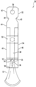
Referring now to FIG. 1, an integrated sampling device 30 according to one
embodiment is illustrated. Overall, the flat design of device 30 aids in
improving the
manufacturability of the device 30. Moreover, the flat design allows multiple
sampling
devices 30 to be connected together for use in a cartridge, such as reel to
reel type
cartridge or a drum in an ACCU-CHEK ADVANTAGE"" brand meter (Roche
Diagnostics Corporation, Indianapolis, Indiana). However, it should be
appreciated that
the integrated sampling device 30 can have a. different overall shape in other
embodiments. For example, it is envisioned that the device 30 in other
embodiments
can be round or cylindrical in shape. The integrated sampling device 30
includes a
connection portion 32 for connecting the integrated sampling device 30 to a
bodily fluid
sampling device, a sampling portion 34 for drawing fluid from the incision
site up for
analysis, and an incision portion 36 for creating an incision in the body part
to be
sampled. The integrated sampling device 30 as illustrated is designed to be
used with a
4
CA 02565229 2006-11-01
WO 2005/107593 PCT/EP2005/004772
variety of bodily fluid sampling devices. Moreover, the integrated sampling
device 30
in the illustrated embodiment is intended to be disposed after one use for
sanitary
reasons. It is contemplated, however, that in other embodiments the integrated
sampling device 30 can be used multiple times after sterilizing between uses.
As
shown, the connection portion 32 includes a connection loop 38 that is
separated from
the sampling portion 34 by notches 40. The notches 40 enable a firing
mechanism of a
bodily fluid sampling device to be attached to the integrated sampling device
30. The
connection loop 38 defines a registration opening 42 that is designed to
position and
secure the integrated sampling device 30 to the bodily fluid sampling device.
The sampling portion 34 includes a body portion 44, spacer members 46, a
capillary
channel or cavity 48, a test media 50 and a collection sheet 52. The
collection sheet
improves fluid sampling and therefore is a preferred feature. Sampling without
the
collection sheet, however, is possible and alternative means may be
contemplated by
the artisan. The flexible sheet is therefore not essential. The body portion
44 provides a
support for the remaining parts of the sampling portion 34 and allows all of
the different
parts to be mounted thereupon. The spacer members 46 define the channel 48
through
which fluid is drawn up to the test media 50 for testing. The collection sheet
52 further
assists in defining the channel 48.
In the illustrated embodiment, the body portion 44 is formed from a metal
lancet. It is
contemplated that in other embodiments the body portion 44 can be formed of a
high-
strength plastic, a composite material, a combination thereof, or other
materials readily
apparent to one skilled in the art. By being substantially flat, the body
portion 44 and
other components can be easily formed from shccts of material, such as metal
or plastic,
and these sheets can be sandwiched together in order to mass produce body
portions 44
and other components. Nonolhcless, it should be appreciated that lhe body
portion 44
can bc shaped differently in alternate enibodiiiieiils.
The spacer members 46 are made of plastic in the illustrated embodiment. It
should be
understood that the spacer members 46 can be formed from other materials, such
as a
bead of adhesive or a piece of metal, to name a few. In one embodiment, the
spacer
5
CA 02565229 2006-11-01
WO 2005/107593 PCT/EP2005/004772
members 46 are coated with an adhesive on one side to fix the spacer members
46 to
the body portion 44. In an alternate embodiment, the spacer members 46 are
fixed to
the body portion 44 using adhesive tape. Moreover, it is contemplated that the
spacer
members 46 may be secured in other manners readily apparent to one skilled in
the art.
In other embodiments, the body portion 44 and the spacer members 46 are
directly
attached to one another.
As shown, the channel 48 in the illustrated embodiment is a rectangularly
shaped
passage. It is contemplated that in other embodiments that this passage
defines a
different geometrical shape. One example, among others, would be a passage
that is
cylindrical in nature. The dimensions of the channel 48 vary in differing
embodiments.
FIG. 1 illustrates an embodiment where the channe148 is sized to draw bodily
fluid via
capillary action. Alternate embodiments contemplate drawing fluid in other
manners,
such as via a vacuum.
Referring to FIG. 1, the test media 50 in the illustrated embodiment is
located at the end
of the channel 48 that is opposite the incision portion 36. However, it should
be
understood that the test media 50 can be located at difference locations along
the
channel 48. The test media 50 is configured to determine analyte levels or
other
properties of the body fluid sample. As should be appreciated, the properties
of the
body fluid sample can be determined through the chemical, electrical,
electrochemical
and/or optical properties of the bodily fluid sample collected on the test
media 50 to
name a few. For example, the test media 50 is illustrated as a chemically
reactive
reagent tcst strip. Optionally, an absorbent pad may be placed belweeri the
lesl slrip in
the closed end of the capillary cllannel 48 for wicking body fluid onto the
test media 50.
The spreading or wicking layers ensure that the fluid is adsorbed uniformly
across the
surface of the test media 50. The uniform application of the fluid assists the
test media
50 in functioning properly. Fluid drains from the capillary into the wick
material and
spreads across the test media 50 for analysis. In one embodiment where the
test media
50 is disposed within the capillary channel 48 no absorbent pad may be needed
because
the test strip will be in direct contact with the body fluid. In one form, the
bodily fluid
is blood and the property test is the level of glucose in the blood. Other
embodiments
6
CA 02565229 2006-11-01
WO 2005/107593 PCT/EP2005/004772
contemplate test media 50 that measure other qualities of the bodily fluid.
One
nonlimiting example would be the pH level of blood or interstitial fluid.
As depicted in FIG. 1, the collection sheet 52 defines one side of the
channe148. In the
illustrated embodiment, the collection sheet 52 is a section of a clear
plastic sheet. The
collection sheet 52 is a flexible sheet in the illustrated embodiment. By
being flexible,
the collection sheet 52 is able to deform during lancing, and yet is able to
contact the
skin without closing the incision in order to wick the fluid from the incision
into the
integrated sampling device 30. Moreover, collection sheet 52 provides a visual
indicator such that the user can see whether the integrated sampling device 30
is
positioned close enough to collect the fluid. In one particular form,
collection sheet 52
is a transparent plastic film so as to allow the user to visualize the
incision and the
droplet of fluid during sampling. Other embodiments use different materials
and colors
of material to form the collection sheet 52. As should be appreciated, in
other
embodiments, the collection sheet 52 can be semi-transparent and/or opaque.
The
collection sheet 52 has a sampling end portion 53 that is configured to
contact the skin
during sampling. The sampling end portion 53 flexes during collection of fluid
so that
only a minimal amount of force is applied to the skin such that the fluid flow
from the
incision is not restricted. In one embodiment, the flow of fluid may be
enhanced by
forming the spacer members 46 and the collection sheet 52 out of a material
that is
hydrophilic, that has been treated to be hydrophilic, or that has been coated
with a
hydrophilic material such as a surfactant or hydrophilic polymers. The
surfaces can
also be treated using polyamides, oxidation (e.g. corona/plasma treatment);
plasma
chemical vapor deposition; vacuum vapor deposition of metals, metaloxides or
non-
melaloxides; or deposition of an element that oxidizes with water. In one
form, the
collection sheet 52 also protects the test iiiedia 50 from external disrupting
conditions.
With reference to FIG. 3, near the incision portion 36, the channel 48 has a
first opening
54 through which the body fluid enters the capillary channel 48. By being
located next
to the incision portion 36, the first opening 54 is able to automatically draw
body fluid
from the incision, once the incision is formed. As illustrated, the sampling
end portion
53 of the collection sheet 52 extends next to the first opening 54 such that
the collection
7
CA 02565229 2006-11-01
WO 2005/107593 PCT/EP2005/004772
sheet 52 is able to assist in automatically drawing fluid into the first
opening 54.
As mentioned before, the body portion 44 as well as the incision portion 33 in
the
illustrated embodiment is made from a flat lancet. As illustrated in FIG. 1,
the incision
portion 36 includes a blade support 56 and a blade 58 for forming an incision
in a body
part. Further, the body portion 44 includes a stop edge 60 at the end
illustrated in FIG.
3. The blade support 56 connects the blade 58 to the body portion 44, and the
blade
support 56 is shaped to spread the strain that is placed on the blade 58. As
depicted, the
blade support 56 converges inwards to eventually form the sides of the blade
58. The
blade 58 is sharp so it can form an incision in the skin, and the stop edge 60
can be used
to limit the penetration depth of the blade 58. However, other types of
mechanisms can
be used to limit the penetration depth of the blade 58 before the skin reaches
the stop
edge 60. In the illustrated embodiment, the blade 58 has a cross sectional
shape that is
rectangular, but the blade 58 can be shaped differently in other embodiments.
For
example, the blade 58 has a circular cross sectional shape in one embodiment,
and the
blade 58 has a slanted shape in an alternate embodiment. Other configurations
of the
blade 58 readily apparent to those skilled in the art are contemplated.
Moreover, even
though the blade 58 is shown as being fixed in position with respect to the
rest of the
device 30, it should be appreciated that the blade 58 in other embodiments can
be
moveable with respect to the rest of the device 30. Although the integrated
sampling
device 30 in FIG. 1 uses the blade 58 to form an incision, it should be
appreciated that
the device 30 can incorporate other means for rupturing the skin, such as a
laser.
Referring to FIG. 2, the body portion 44 of the inlegrated sampling device 30
includes a
coiitacl ur expre55ion surface 64 that defines a second opening 66 for
manually dosing
onto the test media 50. In the illustrated einbodiment, the second opening 66
is
machined into a lancet, but it should be appreciated that the second opening
can be
formed in other ways, such as through photo-etching. The second opening in
FIG. 2 is
generally circular in shape. However, the second opening can be shaped
differently in
other embodiments. As shown, the second opening 66 is positioned over the test
media
50 to ensure the body fluid is directly applied to the test media 50. By
positioning the
second opening 66 directly over or near the test media 50, lesser amounts of
fluid are
8
CA 02565229 2006-11-01
WO 2005/107593 PCT/EP2005/004772
required because the fluid does not have to fill the entire channel 48 before
being
deposited onto the test media 50. Although the second opening 66 in the
illustrated
embodiment is positioned directly over the test media 50, it is contemplated
that in
alternative embodiments, the second opening 66 can be placed partially over
the test
media 50 or to the side of the test media 50. When the body fluid is sampled
through
the first opening 54, the second opening 66 acts as a vent to vent air from
the channel
48. In contrast, when fluid is sampled through the second opening 66, the
first opening
54 can act as a vent. Nevertheless, it should be appreciated that additional
vents can be
formed at other locations in the integrated sampling device 30. For instance,
a vent can
be formed by the channel 48 at the end opposite the incision portion 36. To
prevent
accidental cuts, a protective cap 68 covers the blade 58, as is shown in FIG.
3. The
protective cap 68 also ensures the sterility of the blade 58 before it is used
to form an
incision.
A technique for sampling and analyzing body fluid with the integrated sampling
device
30 will now be described with reference to FIGS. 4 and 5. As noted above, the
integrated sampling device 30 samples fluid in two different ways. First,
fluid is
automatically sampled for analysis via the first opening 54 of the channel 48.
If an
insufficient amount of fluid is collected to allow analysis, the body fluid is
then
sampled manually via the second opening 66. Before fluid is collected with the
second
opening 66, additional fluid can be expressed by pressing the second opening
around
the incision, if needed.
Before forniing an incisioii, the iiitCkratCd sampling device 30 is itistalled
into a hody
fluid sampling device that is able to fire dcvicc 30 into the skin to form an
incision 72.
In one embodiment, the body part in which thP incision is formed is a finger,
and in
another embodiment, the body part is the forearm. It is contemplated, however,
that
fluid can be drawn from other body parts. Once fired the blade 58 penetrates
the skin to
form the incision, and afterwards, the blade 58 is retracted either fully or
partially from
the incision 72. The integrated sampling device 30 can be retracted from the
incision
72 either manually by the user, or automatically through a retraction
mechanism, such
as a spring. Furthermore, the user in other embodiments can manually cut the
skin with
9
CA 02565229 2006-11-01
WO 2005/107593 PCT/EP2005/004772
the blade 58 in order to form the incision. In the embodiment illustrated in
FIG. 4, the
blade 58 is fully retracted from the incision 72 to allow bodily fluid 74 to
flow from the
incision 72.
After lancing, the integrated sampling device 30 is positioned proximal to the
body part
70 in order to collect fluid 74 from the incision 72. As should be
appreciated, the
integrated sampling device 30 simplifies positioning for collecting fluid 74.
The
integrated sampling device 30 does not have to be reoriented or repositioned
after
lancing in order to collect the fluid 74. Moreover, the collection sheet 52
provides a
visual indicator to the user so as to ensure that the integrated sampling
device 30 is
positioned at the appropriate distance from the body part 70 for drawing fluid
74 from
the incision 72. As depicted, the collection sheet 52 is longer than the blade
58 so that
during fluid collection the collection sheet 52 is able contact the body part
70. In other
embodiments, the collection sheet may be shorter than the blade or even the
same
length as the blade. Due to its flexible nature, the collection sheet 52 does
not
substantially compress the body part 70 such that the fluid 74 flow from the
incision 72
is not restricted. In the illustrated embodiment, the collection sheet 52
contacts the
body part 70 when fluid 74 is drawn. However, it is contemplated that the
collection
sheet 52 in other embodiments can be positioned slightly away so as to not
contact the
body part 70, but still close enough to draw the fluid 74. The hydrophilic
qualities of
the collection sheet 52 enhance the fluid flow along the collection sheet 52
and into the
channel 48. As depicted in FIG. 4, body fluid 74 is drawn into the channel 48
via the
first opening 54, and the drawn fluid 74 is transported to the test media 50.
'1'he fluid 74
can then be analyzed with the test media 50 in order to determine the desired
property,
such as selected analyte levels in the fluid 74.
Sometimes the amount of fluid 74 that bleeds (or is expressed) from the
incision 72 is
insufficient to fill the channel 48 such that the test media 50 is unable to
provide
accurate test results. By looking through the collection sheet 52, the user
can visually
determine whether or not a sufficient amount of fluid was drawn into the
channel 48. In
other embodiments, the integrated sampling device 30 can incorporate sensors,
such as
electrodes, that detect the sufficiency of the fluid sample. As previously
mentioned, the
CA 02565229 2006-11-01
WO 2005/107593 PCT/EP2005/004772
integrated sampling device 30 incorporates the second opening 66, which allows
a
second opportunity for the body fluid 74 to be dosed onto the test media 50.
The body
fluid 74 can be dosed a second time after additional fluid 74 bleeds from the
incision 72
and/or after the user expresses additional fluid from the incision 72, either
manually or
automatically. For example, the user can press the expression surface 64
against the
body part 70 to force fluid out of the incision 72 and into the second opening
66. Since
the second opening 66 is positioned closer to the test media 50 as compared to
the first
opening 54, the amount of fluid that must be drawn is significantly lower than
the
amount of fluid that has to be drawn up the channel 48.
FIG. 5 illustrates the integrated sampling device 30 during manual dosing of
the fluid
74 through the second opening 66. Although dosing the body fluid 74 via the
second
opening 66 will be described with respect to manual dosing, it is contemplated
that the
dosing can also occur automatically. In the illustrated embodiment, the user
detaches
the integrated sampling device 30 from the firing mechanism of the body fluid
sampling
device to sample fluid 74 via the second opening 66, but it should be
understood that
the device 30 can remain attached to the body fluid sampling device before
dosing
through the second opening 66 in other embodiments. The user can allow the
body
fluid 74 to naturally bleed from the incision 72 before sampling the fluid via
the second
opening 66. Alternatively or additionally, to increase the amount of body
fluid 74, the
user can express additional body fluid 74 from the incision 72. In the
illustrated
embodiment, the user presses the expression surface 64 that surrounds the
second
opening 66 around the incision 72. The manual compression of the body part 70,
such
as a["inger, forces the body fluid 74 out of thc incision 72 and into the
second opening
66. The body fluid 74 is then directly deposited onto the test media 50, and
the test
media 50 is then used to analyze the fluid sample.
An integrated sampling device 75 according to another embodiment is
illustrated in
FIG. 6. As shown, the sampling device 75 in FIG. 6 shares a number of features
in
common with the one described above, such as the channel 48, test media 50,
collection
sheet 52, first opening 54, and blade 58. However, instead of having a second
opening
formed in the body portion 44 of the sampling device 75, one of the spacers 46
defines
11
CA 02565229 2006-11-01
WO 2005/107593 PCT/EP2005/004772
a second opening 76 through which body fluid 74 can be collected onto the test
media
50. In particular, the spacer 46 on the right lateral side of the sampling
device 75, as
viewed in FIG. 6, includes opposing spacer elements 78 that together define
the second
opening 76 along with the test media 50 and the body portion 44. Similar to
the
previous embodiment, the spacers 46 further define a vent opening 80 for
venting air
from the channel 48 at the end of the channe148 opposite the first opening 54.
Although the second opening 76 is formed in the spacer 46 at the right side in
FIG. 6, it
should be appreciated that the second opening 76 can be formed in either
lateral side or
in both lateral sides of the sampling device 75, however. Like before, the
second
opening 76 can be used to manual dose fluid 74 onto the test media 50 if an
insufficient
amount of fluid 74 is drawn via the first opening 74. As depicted, the sides
of the
second opening 76 are tapered so as to minimize dose hesitation when the fluid
is
sampled. In the illustrated embodiment, the second opening 76 is completely
covered
by the test media 50, but it is envisioned that the second opening 76 can be
offset from
the test media 50 in other embodiments. By forming the second opening 76 in
one of
the spacers 76, manufacturing of the integrated sampling device 75 can be
simplified.
In the above described embodiments, only individual integrated sampling
devices were
shown, but it should be appreciated that these sampling devices can be
incorporated into
a drum or cassette such that multiple integrated sampling devices can be used
together.
For example, multiple integrated sampling devices can be coupled together with
a
flexible sheet so as to form a belt or tape that can be stored in a reel-to-
reel type
cassette. Moreover, it is envisioned that the second opening can be formed at
other
locations on the integrated sampling device, and the sampling devices can
include more
than two openings through which fluid can be samplcd. A1tllough the integrated
sampling devices in the drawings have two or more spacers, it should be
understood
that the sampling devices can include just a single spacer.
While the invention has been illustrated and described in detail in the
drawings and
foregoing description, the same is to be considered as illustrative and not
restrictive in
character, it being understood that only the preferred embodiment has been
shown and
12
CA 02565229 2006-11-01
WO 2005/107593 PCT/EP2005/004772
described and that all changes and modifications that come within the spirit
of the
invention are desired to be protected.
13