Note: Descriptions are shown in the official language in which they were submitted.
CA 02566231 2006-11-08
WO 2005/110255
PCT/US2005/015431
- 1 -
TARGETED BIOPSY DELIVERY SYSTEM
Technical Field
Prostate health is a significant concern for men over the age of fifty.
If prostate cancer is suspected from either a physical examination or
because of a Prostate Specific Antigens test, a biopsy is performed to
collect tissue samples from the prostate for evaluation by a pathologist.
Prostate tumors are small growths scattered about the prostate. For this
reason, a physician will take multiple tissue samples from different areas of
the prostate, typically between 9 and 18 samples.
Background Art
The normal procedure for obtaining biopsy samples with ultrasound
guidance is called Transrectal Ultrasound (TRUS) Guided Prostate Biopsy.
An end-fire ultrasound probe is used, which generates a pie-shaped image
plane. Some end-fire probes are manufactured with a biopsy needle
channel, which passes through the body of the probe at an angle, such that
a biopsy needle set inserted through the biopsy needle channel exits the
channel at a slight angle relative to the body of the probe. Most probes
require a needle set guide tube to be affixed to the probe body, such that a
needle set placed through the guide tube parallels the axis of the probe and
the needle set can be extended beyond the end of the probe. In use for
both, the physician inserts the ultrasound probe, into the rectum, and moves
the probe around until the specific area of the prostate to be sampled is
identified. The physician then bends the probe upward, pointing the biopsy
needle channel or biopsy needle set guide at the targeted area of the
prostate. A needle set is inserted into and through the needle channel or
guide, pushed through the rectum wall and into the prostate.
CA 02566231 2006-11-08
WO 2005/110255
PCT/US2005/015431
- 2 -
Standard coring biopsy needles sets are made from substantially
rigid, coaxially aligned, stainless steel wire and tubing. They are comprised
of two basic components; an inner solid wire stylet with specimen notch and
a hollow outer cutting cannula. Once the needle set is correctly positioned
relative to the area of tissue to be sampled, the inner stylet is quickly
advanced under spring loaded or similar pressure into the prostate tissue.
The tissue to be sampled then "prolapses" into stylet's sample notch cutout.
Almost instantaneously the outer cutting cannula quickly advances, also
under spring loaded pressure, which serves to sever and capture the tissue
that had prolapsed into the stylet notch. The needle set is then removed
from the tissue/patient so that the tissue sample can be extracted from the
needle set and evaluated for the presence of cancer. The physician then
moves the probe around within the rectum to identify the next area of the
prostate to be sampled, and the process is repeated. As noted, between 9
is and 18 samples are typically taken from different areas of the prostate.
Existing biopsy methods suffer from a number of disadvantages.
Because the probe must be physically moved about within the rectum by
hand to identify and target the different areas of the prostate, it is
difficult for
physicians to precisely targeted biopsy sample locations, often causing the
need for additional samples to be taken. Further, if a sample seems to
confirm cancer, it is difficult for the physician to accurately know where in
the prostate the sample was taken from, and so difficult to re-biopsy the
same tissue location to confirm the cancer.
A number of systems or devices have been proposed for the
purpose of better targeting biopsies. Batten, et al, (5,398,690) discloses a
slaved biopsy device, analysis apparatus, and process. In Batten, an
ultrasound device is inserted into the male urinary tract through the penis,
with the biopsy and treatment device inserted transrectally. Chin, et al,
(6,179,249) discloses an ultrasound guided therapeutic and diagnostic
CA 02566231 2006-11-08
WO 2005/110255
PCT/US2005/015431
- 3 -
device. Chin is a flexible ultrasound device used for laproscopic surgery.
Lin (6,261,234) disclosed a method and apparatus for ultrasound imaging
with biplane instrument guidance. Lin's ultrasound device uses two
transducers to create two image planes, and has a biopsy needle guide
which directs a biopsy needle at the intersection of the imaging planes.
Burney, et al (6,447,477) discloses surgical and pharmaceutical site access
guide and methods. Burney shows a biopsy device in which a thick needle
with side exit ports is inserted into the targeted tissue. Biopsy needles are
then inserted into the thick needle, exiting out the side to take samples.
Further, a number of systems have specified the use of flexible biopsy
needle kits.
However, all of these inventions suffer from a number of
disadvantages. All require specialized equipment, and do not make use of
existing ultrasound systems and technology. All require the movement of
the imaging device, making it more difficult to plan and target areas of the
prostate for biopsy. Further, the flexible biopsy needles called out either
require heating or additional force to cause them to fire, and are impractical
for use with established prostate biopsy procedures and existing biopsy
needle set firing devices.
Therefore, users would benefit from a biopsy system to allow a
biopsy to be planned prior to the tissue sampling, to allow the biopsy needle
to be precisely inserted into a targeted area and which is able to record the
precise location from which the tissue sample is collected while the imaging
device remains stationary. Users would also benefit from a flexible needle
set which may be easily "fired" while in a curved position. Further, users
would benefit from a means of precisely delivering a treatment to a targeted
area of an organ or tissue mass.
CA 02566231 2012-11-22
72235-223
4
Summary Of The Invention
It is the principal object of some aspects of this invention to provide a
device and method for precisely planning, undertaking and recording a multi-
sample
biopsy of a targeted tissue mass such as a prostate, improving physicians'
ability to
diagnose cancer.
Another object of some aspects of the invention is to allow a biopsy
plan to be formulated identifying the specific quadrants and areas of the
prostate to
be sampled.
Another object of some aspects of the invention is to allow this biopsy
plan to be saved as a reference point.
Another object of some aspects of the invention is to allow a physician
to adjust the biopsy needle guide to allow the physician to precisely insert
the needle
into the tissue at the planned location.
Another object of some aspects of the invention is to allow a physician
to monitor the needle set as it is inserted into the tissue, to verify that
the needle is in
the planned location.
Another object of some aspects of the invention is to provide a biopsy
needle guide which can be affixed to or associated with existing side-imaging
transrectal ultrasound probes.
A further object of some aspects of the invention is to allow the
transrectal ultrasound probe to remain stationary while the biopsy samples are
gathered from different areas of the prostate, thereby improving the accuracy
of the
procedure.
A further object of some aspects of the invention is to allow the probe to
remain stationary while the needle guide is moved longitudinally along the
probe and
is also rotated around the probe.
CA 02566231 2012-11-22
72235-223
A further object of some aspects of the invention is to provide a needle
set guide which can redirect the needle set such that the needle set can be
curved
while still maintaining the freedom of movement to allow the firing and
collecting of
tissue samples.
5 A further object of some aspects of the invention is to provide a
biopsy
needle set that may be redirected at an angle and further maintains its
ability to be
fired and so collect the tissue samples.
An object of an alternative embodiment of the invention is to allow a
treatment plan to be formulated identifying the specific areas of tissue or an
organ to
be treated.
A further object of an alternative embodiment of the invention is to allow
this treatment plan to be saved as a reference point.
Another object of an alternative embodiment of the invention is to allow
a physician to precisely insert a needle or treatment delivery means into the
tissue at
the planned location.
Another object of some aspects of the invention is to allow a physician
to monitor the needle or treatment delivery method as it is inserted into the
tissue, to
verify that the needle or treatment delivery method is in the planned
location.
These and other objects, advantages and features are accomplished
according to the devices and methods of the following description of
embodiments of
the invention.
As noted some aspects of the present invention relates to a biopsy
targeting system for use with ultrasound imaging devices, and particularly for
use in
sampling prostate tissue. The biopsy targeting system consists of a
redirecting biopsy
needle guide which works in conjunction with a side-view or end-fire
transrectal
ultrasound probe, a cooperating software program which can be loaded and
operated
on a computer controlled ultrasound system, and a bendable needle set.
CA 02566231 2006-11-08
WO 2005/110255
PCT/US2005/015431
- 6 -
In use, the transrectal ultrasound probe is placed in the cradle of a
stabilizer. The redirecting needle guide positioning assembly is also affixed
to the cradle. The physician then advances and adjusts the cradle to allow
the transrectal probe to be inserted into the rectum of a patient. The
physician generates an ultrasound image while positioning the probe to
insure that the patient's prostate is viewable within the viewing area of the
probe. Once the probe is correctly positioned, the physician then locks the
probe in place in the stabilizer.
With the transectal probe in place, the physician initiates a full 3D
io scan of the prostate. The multiple image slices are captured by the
ultrasound system. The physician then looks through these saved images,
to identify possible problem areas of the prostate and further to decide
which areas of the prostate to sample. Typically, physicians collect 9 to 18
tissue samples from different areas of the prostate. As part of this process,
the physician is able to use the software program to project potential needle
path lines onto the images of the prostate. These paths are shown as lines
in views parallel to the needle path and as circles where the paths pierce
the image plane. Each possible path is described by the positional settings
of the redirecting needle guide. When the physician identifies a specific
area to be sampled, the physician moves a projected needle path line to
intersect the planed area to be biopsied. The physician continues to
evaluate the prostate and target additional areas for sampling, again saving
projected needle paths for each planned sample. Further, if the physician
does not identify any possible problem areas, but wishes to take a standard
biopsy, the physician can use a range of default setting on the computer
program to project between 9 and 18 projected needle paths with a
standard distribution throughout the prostate.
Once the biopsy is planned, the physician initiates the biopsy. All of
the needle paths for a given longitudinal image are displayed on the
CA 02566231 2006-11-08
WO 2005/110255
PCT/US2005/015431
- 7 -
ultrasound monitor. The display shows the coordinates of the planned
needle paths which correlate to the positional setting of the redirecting
needle guide. The physician then advances and/or rotates the redirecting
needle guide to the correlating coordinates for the first planned needle path.
The physician then inserts a flexible biopsy needle kit into the redirecting
needle guide's needle insertion point. The needle set is advanced by hand
through the needle set channel, including through the redirecting curve
within the needle guide. This redirecting curve causes the needle to exit
the needle guide, within the rectum of the patient, at an angle relative to
the
transrectal probe. The physician pushes the needle guide through the
tissue of the rectal wall and into the prostate, monitoring the progress of
the
needle on the ultrasound system and insuring that the actual path of the
needle matches the planned needle path being projected on the image.
When the biopsy needle set has achieved the correct depth of penetration,
the physician uses a standard biopsy firing gun to "fire" the needle set,
causing the stylet and cannula to quickly extend in sequence, cutting and
capturing a slice of prostate tissue in the specimen notch of the needle set.
Because the specimen notch is substantially longer than in standard biopsy
needles and the cannula body is flexible, the needle set is very flexible and
able to be fired even though bent. The specimen notch is extended to the
curved portion of the needle set within the redirecting needle set guide,
allowing the stylet to be quickly moved in reference to the cannula without
binding. With the needle still in the prostate, the physician saves the
ultrasound image(s) on the computer program, creating a permanent record
of the biopsy tissue location. The physician then removes the biopsy
needle with captured tissue sample. Once removed, the cannula is
retracted from the stylet, allowing the tissue sample to be placed into a
tissue specimen dish. The physician then advances or moves the
CA 02566231 2012-11-22
72235-223
8
redirecting biopsy needle guide to the next planned needle path location, and
repeats
the procedure.
According to one aspect of the invention, there is provided a targeted
biopsy system comprising: a redirecting guide having a guide body and a needle
set
channel, a flexible biopsy needle set which may be inserted into the needle
set
channel of said redirecting guide for taking biopsies, an ultrasonic system
having an
ultrasonic system CPU, an ultrasonic probe and a monitor, said ultrasonic
probe
comprising a probe tip and a probe imaging window adapted such that said guide
body of said redirecting guide sits atop said probe tip and can be moved in
different
rotational positions and different longitudinal positions relative to said
probe tip, and
said probe tip generating ultrasonic images of a target tissue mass which are
displayed on said monitor, an assembly for controlling rotational position and
longitudinal position of said guide body of said redirecting guide relative to
said probe
tip, and a targeting software system having a transverse image display and a
sagittal
image display, a plurality of needle paths projected onto both said transverse
image
display and said sagittal image display, each said needle path defined by a
corresponding rotational position and longitudinal position of said guide body
of said
redirecting guide relative to said probe tip as controlled by said assembly.
CA 02566231 2012-11-22
72235-223
8a
Brief Description Of The Drawings
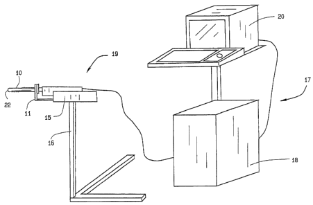
FIG. 1 is a perspective view of targetable biopsy system in
conjunction with an ultrasound imaging system and stabilizer.
FIG. 2 is a perspective view of the redirecting needle set guide
mounted on a side-imaging transrectal ultrasound probe.
FIG 3 is a side view of the redirecting needle set guide mounted on a
io side-imaging
transrectal ultrasound probe, showing the guide positioning
assembly.
FIG. 4 is a planning software interface displayed on the monitor.
FIG. 5 is a schematic of the biopsy planning process.
FIG. 6 is a schematic of the biopsy procedure.
FIG. 7 is a side view of an embodiment of the targetable biopsy
guide.
FIG. 8 is a side cutaway view of an embodiment of the targetable
biopsy guide designed to be manufactured with an insertable metal tube.
FIG. 9 is a side cutaway view of an alternative embodiment of the
targetable biopsy guide.
FIG. 10 is a side cutaway view of an alternative embodiment of the
targetable biopsy guide with an enlarged bend channel.
FIG. 11 shows a side view of a biopsy stylet with extended
specimen notch.
FIG. 12 shows a side view of an alternative embodiment of the stylet
with dual extended specimen notches.
FIG. 13 shows a side view of an alternative embodiment of the stylet
with a tiered specimen notch.
CA 02566231 2006-11-08
WO 2005/110255
PCT/US2005/015431
- 9 -
FIG. 14 shows a side view of an alternative embodiment of the stylet
with multiple notches to facilitate bending
FIG. 15 shows a side view of an embodiment of the cannula in
which the cannula tube has been ground down along its length to leave a
flexible spine.
FIG. 16 shows a side view of an embodiment of the cannula in
which the cannula tube has been spiral-cut along its length to facilitate
bending of the cannula.
FIG. 17 shows a side view of an alternative embodiment of the
cannula in which the tip of the cannula tube is uncut while the body of the
cannula tube has been spiral-cut.
FIG. 18 shows a side view of an alternative embodiment of the
cannula in which sections of the cannula tube alternate between cut and
uncut.
FIG. 19 shows a side view of an embodiment of the cannula in
which the cannula tube is encased in flexible tubing.
FIG. 20 shows a perspective view of an embodiment of the flexible
needle set.
FIG. 21 is a side view of the traditional method of taking a prostate
biopsy with a biopsy needle channel.
FIG. 22 is a side view of the bendable needle and biopsy targeting
system mounted on a side-fired probe taking a biopsy.
FIG. 23 is a side view of the redirecting guide with a flexible needle
set inserted and extending out of the guide such that the needle set is bent
by the needle set channel bend.
CA 02566231 2006-11-08
WO 2005/110255
PCT/US2005/015431
- 10 -
Parts Numbers
Rectum 1
Prostate 2
redirecting guide 10
alternative redirecting guide 10A
positioning assembly 11
targeting software system 12
flexible needle set 13
cradle 15
stabilizer 16
ultrasound system 17
ultrasound system CPU 18
side view transrectal probe 19
monitor 20
probe tip 22
probe imaging window 23
guide body 30
needle set channel 31
needle set insertion point 32
needle set exit point 33
front body guide extensions 34A,
34B
imaging cutout 35
needle set channel bend 36
enlarged bend channel 37
insertable metal tube 38
rotational adjustment collar 40
fixed collar 41
longitudinal slides 42
CA 02566231 2006-11-08
WO 2005/110255
PCT/US2005/015431
-11 -
longitudinal position controller 43
needle path location registry 50
needle path lines 51
needle path dots 52
flexible stylet 60
flexible cannula 61
tip 62
extended specimen notch 63
stylet body 64
cutting tip 65
cannula body 66
counter bore and taper 67
bending notches 70
tiered specimen notch 71
segmented specimen notch 72
removable needle set guide insert 75
stylet hub 76
cannula hub 77
strip 78
depth markings 79
cannula sheath 81
spiral cut 82
non-spiral cut portion 83
beveled edge 84
Biopsy attachment angle selector 201
and display
Biopsy attachment depth selector 202
and display
needle path coordinates display 204
CA 02566231 2006-11-08
WO 2005/110255
PCT/US2005/015431
- 12 -
window
Finished with Biopsy Planning 206
button
Remove selected biopsy location 207
from plan button
Add selected biopsy location to 208
plan button
Select pre-planned template 209
Sagittal image plane selector 210
Transverse image plane selector 211
Transverse image display 212
Sagittal Image display 213
Best Mode for Carrying Out the Invention
As seen in FIG. 1, the targeted biopsy system is comprised of a
redirecting guide 10, positioning assembly 11, targeting software system 12
(loaded on CPU 18) and flexible needle set 13 (best seen in FIG. 20). The
positioning assembly 11 is affixed to cradle 15, which is a part of stepper
and stabilizer 16. Working in conjunction with the targeted biopsy system is
ultrasound system 17, which is comprised of ultrasound system CPU 18,
side view transrectal probe 19 and monitor 20. Side view transrectal probe
is comprised of probe tip 22 and probe imaging window 23. As seen in
FIGS. 2 and 7, the redirecting guide 10 consists of guide body 30, needle
set channel 31, needle set insertion point 32, and needle set exit point 33,
front body guide extensions 34A and 34B, imaging cutout 35. As seen in
FIG 10, needle set channel 31 may be provided with enlarged bend channel
37. As seen in FIG 8, the redirecting guide 10 may be provided with
insertable metal tube 38. In an alternative embodiment, the redirecting
CA 02566231 2006-11-08
WO 2005/110255
PCT/US2005/015431
- 13 -
guide may contain one or more pathways may be used for insertion of the
biopsy needle kit. The redirecting guide may be comprised of a movable
device such that the opening through which the needle kit exits may be
moved relative to the opening into which the biopsy needle kit is placed. In
a further alternative embodiment, the redirecting guide may straighten a
previously curved biopsy needle kit such that the biopsy needle kit re-curve
when leaving the redirecting guide.
As best seen in FIG. 3, positioning assembly 11 is comprised of
rotational adjustment collar 40, fixed collar 41, longitudinal slides 42 and
longitudinal position controller 43.
As best seen in FIG. 4, targeting software system 12 is comprised of
transverse image display 212, Sagittal Image display 213, longitudinal
projected needle path 51 and transverse projected needle path 52, in
addition to various controls.
As best seen in FIG. 20 flexible needle set 13 consists of flexible
stylet 60 and flexible cannula 61. Stylet 60 may be affixed to stylet hub 76,
with cannula 61 affixed to cannula hub 77. Further, cannula 61 may be
provided with depth markings 79. As seen in FIG. 11, the preferred Flexible
stylet 60 consists of tip 62, extended specimen notch 63 and stylet body 64.
As seen in FIG 12, an alternative preferred Flexible stylet 60 consists of tip
62 and segmented specimen notches 72a and 72b. Alternative
embodiments of flexible stylet 60, as seen in FIGS. 13 and 14, contain
bending notches 70 and tiered specimen notch 71.
As seen in FIG 19, the preferred embodiment of cannula 61 consists
of cutting tip 65, cannula body 66 and cannula sheath 81. The cannula
sheath may have beveled edges. As seen in FIG 15, a portion of the body
of flexible cannula 61 has been removed, As seen in FIG 16, cannula body
66 may be provided with spiral cut 82 to facilitate bending. As seen in FIG
17, in an alternative embodiment of cannula 61, cannula body 66 may be
CA 02566231 2006-11-08
WO 2005/110255
PCT/US2005/015431
- 14 -
provided with non-spiral cut portion 83 at cutting tip 65, to facilitate the
straight entry of the cannula into the tissue. As seen in FIG 18, in a further
alternative embodiment of cannula 61, cannula body 66 may be provided
with non-spiral cut portions 83 interspersed with spiral cuts 82. In an
alternative embodiment of flexible cannula 61 consists of a cutting tip
inserted into the flexible cannula body.
It should be noted that both the stylet cannula can be made from a
range of flexible materials, including combinations of one or more materials,
to facilitate the bendability. This may include traditional materials used in
io medical
devices, such as stainless steel, as well as materials such an
nitinol . Furthermore, the cannula design may mirror the stylet, such that
portion or portions of the metal cannula tube are removed to create a metal
component which has a metal cutting tip, a long spine consisting of only a
portion of the cannula wall in the flexible part of the cannula and then the
full tubular cannula. Furthermore, the machine cannula may be partially or
wholly incased in a cannula sheath, which may be plastic or some other
material.
FIG. 21 shows a biopsy being performed using the standard
method, using an end-fire ultrasound probe with a biopsy needle channel.
The probe is inserted into the rectum, and then angled upward until the
probe tip is pointed at the desired portion of the prostate. A needle set is
then inserted through the biopsy needle channel guide into the prostate 2.
In use of the preferred embodiment of the invention, as seen in
FIGS. 1 and 22, side view transrectal probe 19 is mounted on the cradle 15
of a stabilizer 16. Redirecting guide 10 is also mounted on the cradle 15,
such that guide body 30 sits atop probe tip 22. As seen in FIG. 2, front
body extensions 34a and 34b partially wrap around probe tip 22 to help
maintain the guide body 30 on the probe tip 22. The cradle 15 is moved
forward, with the probe tip 22 inserted into patient's rectum 1. Probe tip 22
CA 02566231 2006-11-08
WO 2005/110255
PCT/US2005/015431
- 15 -
is generating ultrasound images, which are displayed on monitor 20. The
physician uses this image to insure that the entirety of prostate 2 is
viewable by probe imaging window 23. Once the probe tip 22 is correctly
positioned, the physician locks in place cradle 15.
The biopsy planning process is illustrated in FIG. 5. A representative
display of the biopsy information to the user is shown in FIG 4.The process
begins with the planning software obtaining a set of volumetric data 101.
The volumetric data consists of two sets of sampled images. One set is of
longitudinal images sampled at a regular angular spacing, and the other is a
m set of
transverse images sampled at regular depth spacing. If only one of
the two sets is available, one may be interpolated from the other. The
physician starts the planning process by pressing button 203 to satisfy step
102 of FIG 4. For 103, the planning system overlays a series of lines 51 a,
b, c, etc. and dots 52 a, b, c, etc. on the images in panes 212 and 213.
These lines and dots represent the available needle paths selectable with
controls 40 and 43, and show where the needle intersects with image
planes. Each line and dot combination is labeled with a coordinate 50
corresponding to a unique pair of setting for controls 40 and 43. The user
can review the stored images using controls 210 and 211 to change the
image viewed. For 104, the user can "simulate" the effect of controls 40
and 43 using on-screen controls 201 and 202 to adjust the selected needle
path. The current path is displayed by changing the color of the appropriate
line and dot (51 and 52, respectively). The user adds a specific needle path
to the biopsy plan (105) by selecting button 208. Each time a path is
selected, a record is placed into needle path coordinates display window
204 showing the coordinates of the path. The user may also remove a
specific path from the plan by selecting button 207. When the plan is
complete, the user clicks on the button 206 to send the planning process
(106).
CA 02566231 2006-11-08
WO 2005/110255
PCT/US2005/015431
- 16 -
Once the biopsy planning process has been completed, the
physician or technician may then proceed with the biopsy procedure, to
complete the series of precision located biopsy's to be taken through the
usage of this instrument. For example, as can be noted in FIG. 6, once a
biopsy procedure has been completed, the physician then determines
whether any more biopsies are needed, and where the biopsy locations
may be determined. This can be seen at 301. If no additional biopsies are
required, this is the end of the procedure. If additional biopsies are
considered as needed, the physician then adjusts the redirection of the
guide 10, and the longitudinal controller 40, to mass the desired biopsy
coordinates, as provided upon the scanner. This can be noted at 302. Then,
the user inserts a needle set 13 into the channel 32, to prepare for
additional biopsies. The physician then inserts the needle into the patient,
moving the needle in and out to adjust for depth, as determined by the
scanner, as can be seen at 304. Then, the physician can determine if the
needle tip is at the correct depth, at 305. If it is not, then the physician
may
move the needle and adjust its depth further. If it is, the physician then
fires
the needle of the biopsy instrument, as at 306. Then the physician removes
the needle set 13 from the patient, having taken the biopsy as required.
Then, the tissue sample is removed from the biopsy needle notch, for
further analysis by the lab. This can be noted at 308. When this is
completed, this concludes the conduct of biopsies upon the patient.
As alternative to the procedure in FIG 4, preplanned biopsy selection
menu 209 allows the user to select a pre-determined needle pattern,
typically 9-12 needle paths, without having to select each needle path
manually. The needle paths generated could need to be adjusted for the
specific size of the organ. The size of the organ can be input by various
means. The planning process allows the physician to modify the needle
paths as needed and to approve that they are correct.
CA 02566231 2006-11-08
WO 2005/110255
PCT/US2005/015431
- 17 -
Projected needle paths 51a, 51b, etc, include needle path location
registry 50, which indicate the horizontal and rotational position of the
needle path in reference to the probe. Working from the saved biopsy plan,
displayed in 204, the physician rotates redirecting guide 10 using rotational
adjustment collar 40, and then advances the redirecting guide using
longitudinal position controller 40, both of which have position information
which correlates to the needle path location registry 50. As seen in FIG.
18, the physician inserts flexible needle set 13 into needle set insertion
point 32 and into needle set channel 31. When the needle set 13 reaches
needle set channel bend 36, the needle set 13 is redirected at an angle
away from the axis of probe tip 22. Needle set 13 exits needle set exit point
33. Because of imaging cutout 35, the physician is able to see the needle
set in the ultrasound image as it exits exit point 33, allowing the physician
to
insure that the needle set 13 is in the path marked by projected needle path
51a. The physician monitors the depth of the needle set 13 as it is pushed
through the rectum wall and into the prostate 2. Once the desired depth is
reached, the physician stops inserting the needle set 13. Using a standard
biopsy gun, the needle set 13 is "fired". This causes flexible stylet 60 to
rapidly advance a short distance, such that tissue from the prostate two
prolapses into extended specimen notch 63. Almost instantaneously
flexible cannula 61 quickly advances, also under spring loaded pressure or
other motivational means, which serves to sever and capture the tissue that
had prolapsed into the extended specimen notch 63. Because the
extended specimen notch 63 extends to the point where flexible needle set
13 is bent in needle set channel bend, the stylet and cannula are able to fire
without the two pieces binding together, allowing the specimen to be
effectively captured. The physician then removes the flexible needle set 13
with the captured specimen. The specimen is removed from the flexible
needle set, and the physician then resets the redirecting guide to the
CA 02566231 2006-11-08
WO 2005/110255
PCT/US2005/015431
- 18 -
coordinates of the next saved projected needle path 51b. The process is
repeated until the physician has captured all of the samples as planned
using the targeting software system 12.
FIG. 23 provides a side cut-away view of the redirecting guide with a
flexible needle set inserted and extending out of the guide such that the
extended specimen notch is bent by the needle set channel bend.
In an alternative embodiment of the invention, the invention is used
to plan and perform a targeted treatment of an organ or tissue mass. With
the device in place, the process begins with the planning software obtaining
io a set of volumetric data. The planning system overlays a series of
needle
path lines and needle path dots on the images in panes 212 and 213, which
represent the available needle paths with coordinates that match the
coordinates on rotational adjustment collar 40 and longitudinal position
controller 43 of positioning assembly 11. The user selects specific needle
is paths, which are saved the treatment plan.
Preplanned treatment
selections allow the user to select a pre-determined needle pattern without
having to select each needle path manually.
Working from the saved treatment plan, the physician rotates
redirecting guide using rotational adjustment collar, and then advances the
20 redirecting guide using longitudinal position controller, both of
which have
position information which correlates to the needle path location registry.
The physician' then inserts a flexible needle set or treatment delivery means
into needle set insertion point 32 and into needle set channel 31. When the
needle set or treatment delivery means reaches the needle set channel
25 bend, the needle set or treatment delivery method is redirected at
an angle
away from the axis of probe tip 22. Needle set 13 exits needle set exit point
33. Because of imaging cutout 35, the physician is able to see the needle
set or treatment delivery method in the ultrasound image as it exits exit
point 33. The physician monitors the depth of the needle set or treatment
CA 02566231 2006-11-08
WO 2005/110255
PCT/US2005/015431
- 19 -
delivery method as it is pushed into the targeted organ or tissue mass.
Once the desired depth is reached, the physician is able to undertake the
preferred activity. This may include using the delivery means to inject a
solid, gas or liquid material or other treatment apparatus into the targeted
organ or tissue mass. Further, the physician may insert an organism into
the targeted organ or tissue mass. The material may be deposited and left
in the targeted organ or tissue mass. Further, material previously deposited
may be removed. The use of the deposited material may be as a
treatment, a marker, or other uses. Further, the delivery means may be
used to apply energy to a targeted organ or tissue mass, including but not
limited to heat, cold, light and radiation. Once the treatment or marking is
delivered, the physician then removes the flexible needle set or treatment
delivery method, and then resets the redirecting guide to the coordinates of
the next saved projected needle path. The physician has the option of
saving the image of the treatment needle in the targeted organ or tissue
mass, to record the location of the treatment as delivered. The process is
repeated until the physician has treated or marked all of the targeted areas
of the organ or tissue mass.