Note: Descriptions are shown in the official language in which they were submitted.
CA 02566270 2006-11-08
WO 2005/113889
PCT/US2005/015562
WI-PROVED SEAM FOR MULTIAXIAL PAPERMAKING FABRICS
BACKGROUND OF THE INVENTION
Field of the Invention
The present invention relates to the seaming of multiaxial fabrics on a
papermaking machine.
Description of the Prior Art
During the papermaking process, a cellulosic fibrous web is formed by
depositing a fibrous slurry, that is, an aqueous dispersion of cellulose
fibers,
onto a moving forming fabric in the forming section of a paper machine. A
large amount of water is drained from the slurry through the forming fabric,
leaving the cellulosic fibrous web on the surface of the forming fabric.
The newly formed cellulosic fibrous web proceeds from the forming
section to a press section, which includes a series of press nips. The
cellulosic
fibrous web passes through the press nips supported by a press fabric, or, as
is
often the case, between two such press fabrics. In the press nips, the
cellulosic
fibrous web is subjected to compressive forces which squeeze water therefrom,
and which adhere the cellulosic fibers in the web to one another to turn the
cellulosic fibrous web into a paper sheet. The water is accepted by the press
fabric or fabrics and, ideally, does not return to the paper sheet.
The paper sheet finally proceeds to a dryer section, which includes at
least one series of rotatable dryer drums or cylinders, which are internally
heated by steam. The newly formed paper sheet is directed in a serpentine path
sequentially around each in the series of drums by a dryer fabric, which holds
the paper sheet closely against the surfaces of the drums. The heated drums
reduce the water content of the paper sheet to a desirable level through
evaporation.
It should be appreciated that the forming, press and dryer fabrics all take
the form of endless loops on the paper machine and function in the manner of
conveyors. It should further be appreciated that paper manufacture is a
continuous process which proceeds at considerable speeds. That is to say, the
1
CA 02566270 2006-11-08
WO 2005/113889
PCT/US2005/015562
fibrous slurry is continuously deposited onto the forming fabric in the
forming
section, while a newly manufactured paper sheet is continuously wound onto
rolls after it exits from the dryer section.
The present invention relates primarily to the fabrics used in the press
section, generally known as press fabrics, but it may also find application in
the
fabrics used in the forming and dryer sections, as well as in those used as
bases
for polymer-coated paper industry process belts, such as, for example, long
nip
press belts.
Press fabrics play a critical role during the paper manufacturing process.
One of their functions, as implied above, is to support and to carry the paper
product being manufactured through the press nips.
Press fabrics also participate in the finishing of the surface of the paper
sheet. That is, press fabrics are designed to have smooth surfaces and
uniformly
resilient structures, so that, in the course of passing through the press
nips, a
smooth, mark-free surface is imparted to the paper.
Perhaps most importantly, the press fabrics accept the large quantities of
water extracted from the wet paper in the press nip. In order to fulfill this
function, there literally must be space, commonly referred to as void volume,
within the press fabric for the water to go, and the fabric must have adequate
permeability to water for its entire useful life. Finally, press fabrics must
be
able to prevent the water accepted from the wet paper from returning to and
rewefting the paper upon exit from the press nip.
Contemporary press fabrics are used in a wide variety of styles designed
to meet the requirements of the paper machines on which they are installed for
the paper grades being manufactured. Generally, they comprise a woven base
fabric into which has been needled a batting of fine, non-woven fibrous
material. The base fabrics may be woven from monofilament, plied
monofilament, multifilament or plied multifilament yarns, and may be single-
layered, multi-layered or laminated. The yarns are typically extruded from any
one of several synthetic polymeric resins, such as polyamide and polyester
resins, used for this purpose by those of ordinary skill in the paper machine
clothing arts.
2
CA 02566270 2006-11-08
WO 2005/113889
PCT/US2005/015562
Woven fabrics take many different forms. For example, they may be
woven endless, or flat woven and subsequently rendered into endless form with
a seam. Alternatively, they may be produced by a process commonly known as
modified endless weaving, wherein the widthwise edges of the base fabric are
provided with seaming loops using the machine-direction (MD) yarns thereof.
In this process, the MD yarns weave continuously back and forth between the
widthwise edges of the fabric, at each edge turning back and forming a seaming
loop. A base fabric produced in this fashion is placed into endless form
during
installation on a paper machine, and for this reason is referred to as an on-
machine-seamable fabric. To place such a fabric into endless form, the two
widthwise edges are seamed together. To facilitate seaming, many current
fabrics have seaming loops on the crosswise edges of the two ends of the
fabric.
The seaming loops themselves are often formed by the machine-direction (MD)
yarns of the fabric. The seam is typically formed by bringing the two ends of
the press fabric together, by interdigitating the seaming loops at the two
ends of
the fabric, and by directing a so-called pin, or pintle, through the passage
defined by the interdigitated seaming loops to lock the two ends of the fabric
together.
Further, the woven base fabrics may be laminated by placing one base
fabric within the endless loop formed by another, and by needling a staple
fiber
batting through both base fabrics to join them to one another. One or both
woven base fabrics may be of the on-machine-seamable type.
In any event, the woven base fabrics are in the form of endless loops, or
are seamable into such forms, having a specific length, measured
longitudinally
therearound, and a specific width, measured transversely thereacross. Because
paper machine configurations vary widely, paper machine clothing
manufacturers are required to produce press fabrics, and other paper machine
clothing, to the dimensions required to fit particular positions in the paper
machines of their customers. Needless to say, this requirement makes it
difficult
to streamline the manufacturing process, as each press fabric must typically
be
made to order.
3
=
CA 02566270 2012-09-17
=
Application No. 2,566,270 Attorney Docket No. 17648-139
Fabrics in modern papermaking machines may have a width of from 5 to
over 33 feet, a length of from 40 to over 400 feet and weigh from
approximately
100 to over 3,000 pounds. These fabrics wear out and require replacement.
Replacement of fabrics often involves taking the machine out of service,
removing the worn fabric, setting up to install a fabric and installing the
new
fabric. While many fabrics are endless, about half of those used in press
sections of the paper machines today are on-machine-seamable. Some Paper
Industry Process Belts (PIPBs) are contemplated to have an on machine seam
capability, such as some transfer belts, known as Transbelt . Installation of
the
fabric includes pulling the fabric body onto a machine and joining the fabric
ends to form an endless belt.
In response to this need to produce press fabrics in a variety of lengths
and widths more quickly and efficiently, press fabrics have been produced in
recent years using a spiral winding technique disclOsed in commonly assigned
U.S. Patent No. 5,360,656 to Rexfelt et al.
U.S. Patent No. 5,360,656 shows a press fabric comprising a base fabric
having one or more layers of staple fiber material needled thereinto. The base
fabric comprises at least one layer composed of a spirally wound strip of
woven
fabric having a width which is smaller than the width of the base fabric. The
base fabric is endless in the longitudinal, or machine, direction. Lengthwise
threads of the spirally wound strip make an angle with the longitudinal
direction
of the press fabric. The strip of woven fabric may be flat-woven on a loom
which is narrower than those typically used in the production of paper machine
clothing.
The base fabric comprises a plurality of spirally wound and joined turns
of the relatively narrow woven fabric strip. The fabric strip is woven from
lengthwise (warp) and crosswise (filling) yarns. Adjacent turns of the
spirally
wound fabric strip may be abutted against one another, and the spirally
continuous seam so produced may be closed by sewing, stitching, melting,
welding (e.g. ultrasonic) or gluing. Alternatively, adjacent longitudinal edge
portions of adjoining spiral turns may be arranged overlappingly, so long as
the
4
CA 02566270 2006-11-08
WO 2005/113889
PCT/US2005/015562
edges have a reduced thickness, so as not to give rise to an increased
thickness
in the area of the overlap. Alternatively still, the spacing between
lengthwise
yarns may be increased at the edges of the strip, so that, when adjoining
spiral
turns are arranged overlappingly, there may be an unchanged spacing between
lengthwise threads in the area of the overlap.
In any case, a base fabric, taking the form of an endless loop and having
an inner surface, a longitudinal (machine) direction and a transverse (cross-
machine) direction, is the result. The lateral edges of the base fabric are
then
trimmed to render them parallel to its longitudinal (machine) direction. The
angle between the machine direction of the base fabric and the spirally
continuous seam may be relatively small, that is, typically less than 10 . By
the
same token, the lengthwise (warp) yarns of the fabric strip make the same
relatively small angle with the longitudinal (machine) direction of the base
fabric. Similarly, the crosswise (filling) yarns of the fabric strip, being
substantially perpendicular to the lengthwise (warp) yarns, make the same
relatively small angle with the transverse (cross-machine) direction of the
base
fabric. Note, the crosswise and lengthwise yarns in the fabric strip may slip
such that they are not always perpendicular to one another. In short, neither
the
lengthwise (warp) nor the crosswise (filling) yarns of the fabric strip align
with
the longitudinal (machine) or transverse (cross-machine) directions of the
base
fabric.
A press fabric having such a base fabric may be referred to as a
multiaxial press fabric. Whereas the standard press fabrics of the prior art
have
three axes: one in the machine direction (MD), one in the cross-machine
direction (CD), and one in the z-direction, which is through the thickness of
the
fabric, a multiaxial press fabric has not only these three axes, but also has
at
least two more axes defined by the directions of the yarn systems in its
spirally
wound layer or layers. Moreover, there are multiple flow paths in the z-
direction of a multiaxial press fabric. As a consequence, a multiaxial press
fabric has at least five axes. Because of its multiaxial structure, a
multiaxial
press fabric having more than one layer exhibits superior resistance to
nesting
and/or to collapse in response to compression in a press nip during the
5
CA 02566270 2012-09-17
Application No. 2,566,270
Attorney Docket No. 17648-139
papermaking process as compared to one having base fabric layers whose. Yarn
systems are parallel to one another.
Until recently, multiaxial press fabrics of the foregoing type had been
produced only in endless form. As such, their use had been limited to press
sections having cantilevered press rolls and other components, which permit an
endless press fabric to be installed from the side of the press section.
However,
their relative ease of manufacture and superior resistance to compaction
contributed to an increased interest and a growing need for a multiaxial press
fabric which could be seamed into endless form during installation on a press
section, thereby making such press fabric available for use on paper machines
lacking cantilevered components. On-machine-seamable multiaxial press
fabrics, developed to meet this need, are shown in commonly assigned U.S.
Patents Nos. 5,916,421; 5,939,176; and 6,117,274 to Yook.
U.S. Patent No. 5,916,421 shows an on-machine-seamable multiaxial
press fabric for the press section of a paper machine made from a base fabric
layer assembled by spirally winding a fabric strip in a plurality of
contiguous
turns, each of which abuts against and is attached to those adjacent thereto.
The
resulting endless base fabric layer is flattened to produce first and second
plies
joined to one another at folds at their widthwise edges. Crosswise yarns are
removed from each turn of the fabric strip at folds at the widthwise edges to
produce unbound sections of lengthwise yarns. A seaming element, having
seaming loops along one of its widthwise edges, is disposed between the first
and second fabric plies at each of the folds at the two widthwise edges of the
flattened base fabric layer. The seaming loops extend outwardly between the
unbound sections of the lengthwise yams from between the first and second
fabric plies. The first and second fabric plies are laminated to one another
by
needling staple fiber batting material therethrough. The press fabric is
joined
into endless form during installation on a paper machine by directing a pintle
through the passage formed by the interdigitation of the seaming loops at the
two widthwise edges.
6
CA 02566270 2006-11-08
WO 2005/113889
PCT/US2005/015562
U.S. Patent No. 5,939,176 also shows an on-machine-seamable
multiaxial press fabric. Again, the press fabric is made from a base fabric
layer
assembled by spirally winding a fabric strip in a plurality of contiguous
turns,
each of which abuts against and is attached to those adjacent thereto. The
resulting endless fabric layer is flattened to produce a first and second
fabric
plies joined to one another at folds at their widthwise edges. Crosswise yarns
are removed from each turn of the fabric strip at the folds at the widthwise
edges to produce seaming loops. The first and second plies are laminated to
one
another by needling staple fiber batting material therethrough. The press
fabric
is joined into endless form during installation on a paper machine by
directing a
pintle through the passage formed by the interdigitation of the seaming loops
at
the two widthwise edges.
Finally, in U.S. Patent No. 6,117,274, another on-machine-seamable
multiaxial press fabric is shown. Again, the press fabric is made from a base
fabric layer assembled by spirally winding a fabric strip in a plurality of
contiguous turns, each of which abuts against and is attached to those
adjacent
thereto. The resulting endless fabric layer is flattened to produce a first
and
second fabric plies joined to one another at folds at their widthwise edges.
Crosswise yarns are removed from each turn of the fabric strip at the folds at
the widthwise edges to produce unbound sections of lengthwise yarns.
Subsequently, an on-machine-seamable base fabric, having seaming loops along
its widthwise edges, is disposed between the first and second fabric plies of
the
flattened base fabric layer. The seaming loops extend outwardly between the
unbound sections of the lengthwise yarns from between the first and second
fabric plies. The first fabric ply, the on-machine-seamable base fabric and
the
second fabric ply are laminated to one another by needling staple fiber
batting
material therethrough. The press fabric is joined into endless form during
installation on a paper machine by directing a pintle through the passage
formed
by the interdigitation of the seaming loops at the two widthwise edges.
A seam is generally a critical part of a seamed fabric, since uniform
paper quality, low marking and excellent runnability of the fabric require a
seam which is as similar as possible to the rest of the fabric in respect of
7
CA 02566270 2006-11-08
WO 2005/113889
PCT/US2005/015562
properties such as thickness, structure, strength, permeability etc. It is
important
that the seam region of any workable fabric behave under load and have the
same permeability to water and to air as the rest of the fabric, thereby
preventing periodic marking of the paper product being manufactured by the
seam region. Despite the considerable technical obstacles presented by these
seaming requirements, it is highly desirable to develop seamable fabrics,
because of the comparative ease and safety with which they can be installed.
As discussed above in reference to U.S. Patent No. 5,939,176, a CD area
of the multiaxial fabric is raveled out and the fabric is then folded over in
this
raveled area to produce seaming loops. A drawback to this approach of creating
a seam in the multiaxial fabric structure is the CD yam tails that result in
the
seam area. These tails are a function of the CD yam angle which is linked to
the panel width, fabric length and panel skew. These yarn tails are not
anchored
into the base weave and are free to move or "migrate" into the seam area. This
problem is known as yam migration. When this migration occurs, the CD ends
move into the seam area and impede seaming (sometimes significantly). In
addition, these unbound yarns do not provide suitable uniform support for the
fiber batting material in the seam area.
Attempts have been made to use certain adhesives to bind these yams
and prevent migration, but with limited success. Therefore, a need exists for
an
improved seam to prevent yam migration in multiaxial fabrics.
SUMMARY OF THE INVENTION
The present invention is an improved seam for multiaxial fabrics. The
method provides a solution to the problem of yam migration in the seam area.
Further, the improved seam provides suitable uniform support for the fiber
batting material in the seam area.
It is therefore an object of the invention to overcome the above
mentioned problems when seaming a papermaking fabric.
Accordingly, the present invention is both a method for seaming a
papermaker's fabric, and the fabric seam made in accordance with the method.
8
CA 02566270 2006-11-08
WO 2005/113889
PCT/US2005/015562
The present invention is a method of seaming an on-machine-seamable
multiaxial papermaker's fabric. The fabric is in the form of an endless loop
flattened into two layers along a first fold and a second fold. Yams in the
cross-
machine direction (CD) are removed from the first and second folds to create
ravel areas. This leaves the yams in the machine direction (MD) unbound in
the ravel areas. Seam loops are formed from the unbound MD yams at the first
and second folds. CD materials (e.g. continuous CD yarns) are affixed,
rewoven or sewn into the fabric along the edges of the ravel area at each
fold.
The affixed CD materials act to bind the body yarn segments along the CD
edges of the ravel areas. The fabric is seamed by interdigitating the seam
loops
from the first and second folds and inserting a pintle therethrough.
The method may further comprise a step of reweaving at least one
additional CD yarn into the ravel areas to impart desired characteristics to
the
seam area of the fabric. This additional CD yarn may be a yarn or yams or
string material as set forth in U.S. Patent No. 5,476,123, sometimes referred
to
herein as "Circumflex", a tradename of Albany International. The affixed CD
materials may be made of yarn having a thermofusible sheath or pre-attached
layer of thermofusible fiber, or a spun yarn of thermofusible material. The
diameter of the affixed CD materials may be less than the diameter of the CD
yarns in the fabric, thereby reducing the plane difference in the seam. Also,
the
ravel areas may be made wider than normal to accommodate the rewoven
affixed CD materials in the seam loops.
Other aspects of the present invention include that the yarns in the fabric
are at a slight angle with respect to the CD and MD; and therefore some of the
yarns removed in the CD along the edges of the ravel areas do not extend
across
the entire width of the fabric, leaving both complete yarns and small segments
in the CD which are problematic if they migrate into the seam loop area. The
fabric is formed of a woven fabric strip having a width that is less than a
width
of the fabric, the fabric strip being in the form of a multi-layer weave with
two
lateral edges; wherein the lateral edges are formed such that when the fabric
strip is wound around in a continuous spiral fashion to form the fabric, the
lateral edges abutting or overlapping one another to form a spiral seam.
9
CA 02566270 2006-11-08
WO 2005/113889
PCT/US2005/015562
Still further aspects of the present invention include that the fabric is
preferably an on-machine-seamable multiaxial press fabric for the press
section
of a paper machine. At least one layer of staple fiber batting material may be
needled into the fabric. At least some of the yams may be one of polyamide,
polyester, polybutylene terephthalate (PBT), or other resins commonly used to
form yarns used in the manufacture of papermaking fabrics. Any of the yarns
may have a circular cross-sectional shape, a rectangular cross-sectional shape
or
a non-round cross-sectional shape.
The present invention will now be described in more complete detail
with frequent reference being made to the drawing figures, which are
identified
below.
BRIEF DESCRIPTION OF THE DRAWINGS
For a more complete understanding of the invention, reference is made
to the following description and accompanying drawings, in which:
FIG. 1 is a top plan view of a multiaxial base fabric in a flattened
condition;
FIG. 2 is a plan view of a portion of the surface of the multiaxial base
fabric layer;
FIG. 3 is a schematic cross-sectional view of the flattened base fabric
layer taken as indicated by line 6--6 in FIG. 1;
FIG. 4 is a schematic cross-sectional view, analogous to that provided in
FIG. 3, following folding along the ravel area;
FIG. 5 is a plan view of the portion of the surface of the base fabric
layer shown in FIG. 2 following the removal of crosswise yarns to form a ravel
area;
FIG. 5A is a top view of the ravel area in a multiaxial base fabric layer
as shown in FIG. 5;
FIG. 6 is a schematic cross-sectional view of the flattened base fabric
showing the formation of seaming loops along the fold;
FIG. 7 is a schematic cross-sectional view of a seamed multiaxial press
fabric as installed on a papermaking machine;
CA 02566270 2006-11-08
WO 2005/113889
PCT/US2005/015562
FIG. 8 is a top view of the seam area of a seamed multiaxial press fabric
as shown in FIG. 7;
FIG. 9 is an enlarged schematic cross-sectional view of the seam loop
area of the flattened base fabric;
FIG. 10 is an enlarged schematic cross-sectional view of the seam loop
area of the flattened base fabric showing a rewoven continuous CD yam to
prevent yam migration in accordance with the present invention;
FIG. 11 is a plan view of the portion of the surface of the base fabric
layer similar to that shown in FIG. 5 showing reweaving of continuous CD
yams in the raveled area to prevent yarn migration in accordance with the
present invention;
FIG. 12 is a top view of a multiaxial base fabric layer having a yam
sewn in a zigzag pattern into the raveled seam area to prevent yarn migration
in
accordance with an embodiment of the present invention;
FIG. 13 is a top view of a seam loop edge of a multiaxial base fabric
layer showing a yarn blanket-stitched along the seam edge to prevent yarn
migration in accordance with another embodiment of the present invention;
FIG. 14 is a top view of a seam loop edge of a multiaxial base fabric
layer showing a yarn stitched in a zigzag pattern along the seam edge to
prevent
yarn migration in accordance with another embodiment of the present
invention;
FIG. 15 is a top view of a low melt nonwoven layer inserted into the
fold area of a multiaxial base fabric layer prior to heat-setting the seam
loops to
prevent yarn migration in accordance with still another embodiment of the
present invention;
FIG. 16 is a plan view of a multiaxial base fabric layer having a
Circumflex yarn sewn into the vertical raveled seam area and held in place by
a
fine monofilament in a zigzag pattern in accordance with the teachings of the
present invention;
FIG. 17 is a plan view of a multiaxial base fabric layer having a
Circumflex yam sewn into an edge of the vertical raveled seam area and held in
11
CA 02566270 2006-11-08
WO 2005/113889
PCT/US2005/015562
place by a fine monofilament in a zigzag pattern in accordance with the
teachings of the present invention;
FIG. 18 is a plan view of a multiaxial base fabric layer having a thin
monofilament or fine sheath/core yam straight stitched into the vertical
raveled
seam area in accordance with the teachings of the present invention;
FIG. 19 is a plan view of a multiaxial base fabric layer having two
different yarns sewn into an edge of the vertical raveled seam area by two
rows
of stitching in accordance with the teachings of the present invention;
FIG. 20 is a plan view of a multiaxial base fabric layer having two
different yarns sewn into the vertical raveled seam area by one row of
stitching
in a two-step zigzag pattern in accordance with the teachings of the present
invention;
FIG. 21 is a plan view of a multiaxial base fabric layer having a
Circumflex yarn sewn into an edge of the vertical raveled seam area and held
in
place by a fine monofilament in another stitching pattern in accordance with
the
teachings of the present invention;
FIG. 22 is a plan view of a multiaxial base fabric layer having two
Circumflex yams sewn on top of the vertical raveled seam area and held in
place by a monofilament on the backside in a zigzag pattern using twin needles
in accordance with the teachings of the present invention; and
FIG. 23 is a plan view of a multiaxial base fabric layer having a
Circumflex yarns sewn into the backside of the vertical raveled seam area and
held in place by a monofilament on the top and bottom using twin needles in
accordance with the teachings of the present invention.
DETAILED DESCRIPTION OF THE PREFERRED EMBODIMENTS
The preferred embodiments of the present invention will now be
described by reference to Figure 1. Figure 1 is a top plan view of a
multiaxial
base fabric in a flattened condition. Once the base fabric 22 has been
assembled, as taught in commonly assigned U.S. Patents Nos. 5,916,421;
5,939,176; and 6,117,274 to Yook described hereinabove, it is flattened as
shown in the plan view presented in FIG. I. This places base fabric layer 22
12
CA 02566270 2006-11-08
WO 2005/113889
PCT/US2005/015562
into the form of a two-ply fabric of length, L, which is equal to one half of
the
total length, C, of the base fabric layer 22 and width, W. Seam 20 between
adjacent turns of woven fabric strip 16 slants in one direction in the topmost
of
the two plies, and in the opposite direction in the bottom ply, as suggested
by
the dashed lines in FIG. 1. Flattened base fabric layer 22 has two widthwise
edges 36.
FIG. 3 is a schematic cross-sectional view taken as indicated by line 6--
6 in FIG. 1. In accordance with the present invention, a plurality of
crosswise
yarns 28 of fabric strip 16 and of segments thereof are removed from adjacent
the folds 38 to produce a first fabric ply 40 and a second fabric ply 42
joined to
one another at their widthwise edges 36 by unbound sections of lengthwise
yarns 26. FIG. 4 is a schematic cross-sectional view, analogous to that
provided
in FIG. 3, of one of the two widthwise edges 36 of the flattened base fabric
layer 22 following the removal of the crosswise yarns. These unbound sections
44 of lengthwise yarns 26 ultimately form seaming loops for use in joining the
papermaker's fabric to be produced from base fabric layer 22 into endless form
during installation on a paper machine, as taught in the Yook '176 patent.
FIG. 2 is a plan view of a portion of the surface of the multiaxial base
fabric layer at a point on one of the folds 38 near the spirally continuous
seam
20 between two adjacent spiral turns of fabric strip 16. Lengthwise yarns 26
and crosswise yarns 28 are at slight angles with respect to the machine
direction
(MD) and cross-machine direction (CD), respectively.
The fold 38, which is flattened during the removal of the neighboring
crosswise yarns 28, is represented by a dashed line in FIG. 2. In practice,
the
base fabric layer 22 would be flattened, as described above, and the folds 38
at
its two widthwise edges 36 marked in some manner, so that its location would
be clear when it was flattened. In order to provide the required unbound
sections of lengthwise yarns 26 at the fold 38, it is necessary to remove the
crosswise yarns 28 from a region, defined by dashed lines 46,48 equally
separated from fold 38 on opposite sides thereof. This process, called
raveling,
creates a ravel area in the fabric.
13
CA 02566270 2006-11-08
WO 2005/113889
PCT/US2005/015562
FIG. 5 is a plan view of the portion of the surface of the base fabric
layer shown in FIG. 2 following the removal of crosswise yarns from the region
centered about the fold 38. Unbound sections 44 of lengthwise yarns 26 extend
between dashed lines 46,48 in the region of the fold 38. The portion of
crosswise yarn 50 which extended past dashed line 46 has been removed, as
noted above.
The provision of the unbound sections of lengthwise yarns 26 at the two
widthwise edges 36 of the flattened base fabric layer 22 is complicated by two
factors. Firstly, because the fabric strip 16 has a smaller width than the
base
fabric layer 22, its crosswise yarns 28 do not extend for the full width of
the
base fabric layer 22. Secondly, and more importantly, because the fabric strip
16 is spirally wound to produce base fabric layer 22, its crosswise yarns do
not
lie in the cross-machine direction of the base fabric layer 22 and therefore
are
not parallel to the folds 38. Instead, the crosswise yarns 28 make a slight
angle,
typically less than 10 degrees, with respect to the cross-machine direction of
the
base fabric layer 22. Accordingly, in order to provide the unbound sections of
lengthwise yarns 26 at folds 38, crosswise yarns 28 must be removed in a
stepwise fashion from the folds 38 across the width, W, of the base fabric
layer
22.
In other words, since the crosswise yarns 28 are not parallel to fold 38 or
dashed lines 46,48, in multiaxial fabrics it is often necessary to remove only
a
portion of a given crosswise yam 28, such as in the case with crosswise yarn
50
in FIG. 2, in order to clear the space between dashed lines 46,48 of crosswise
yarns 28.
FIG. 5A is a top view of the ravel area in a multiaxial base fabric layer
as shown in FIG. 5. Note the CD yarns (horizontal in this view) along the
edges
of the ravel area do not extend across the entire fabric, but are clipped at
some
point as they angle into the ravel area. These clipped CD yarns 50 are
referred
to as CD tails. Because the CD tails do not fully extend across the fabric,
they
are particularly susceptible to migration into the ravel/seam loop area.
FIG. 6 is a schematic cross-sectional view of the flattened base fabric
showing an exemplary method of forming seaming loops along the fold. In this
14
CA 02566270 2006-11-08
WO 2005/113889
PCT/US2005/015562
particular method, a loop-forming cable 52 is installed between first fabric
ply
40 and second fabric ply 42 and against unbound sections of lengthwise yarns
26. Stitches 54, for example, may be made to connect first fabric ply 40 to
second fabric ply 42 adjacent to loop-forming cable 52 to form seaming loops
56 from the unbound sections of the lengthwise yarns 26. Alternatively, first
fabric ply 40 may be connected to second fabric ply 42 adjacent to loop-
forming cable 52 by any of the other means used for such a purpose by those or
ordinary skill in the art. Loop-forming cable 52 is then removed leaving the
seaming loops 56 formed in the foregoing manner at the two widthwise edges
36 of the flattened base fabric layer 22.
FIG. 7 is a schematic cross-sectional view of a seamed multiaxial press
fabric as installed on a papermaking machine. Figure 7 shows a laminated
fabric comprising the flattened base fabric layer 22 raveled at both folds
with
projecting seam loops resulting in on-machine-seamable base fabric 60. The
ends of on-machine-seamable base fabric 60 are joined to one another by one or
more layers of staple fiber batting material 80 needled into and through the
base
fabric 60 to complete the manufacture of the present on-machine-seamable
laminated multiaxial press fabric. The staple fiber batting material 80 is of
a
polymeric resin material, and preferably is of a polyamide or polyester resin.
The seaming loops 56 of the base fabric layer are interdigitated together and
a
seam is formed by the insertion of pintle 58.
FIG. 8 is a top view of the seam area of a seamed multiaxial press fabric
as shown in FIG. 7. As discussed above, a major drawback of creating a seam
in the multiaxial structure are the CD tails that result in the seam area.
Figure 8
shows CD tails 100 which have migrated into the seam area. The tails are a
function of the CD yarn angle which is linked to the panel width, fabric
length
and panel skew of the multiaxial fabric base. These CD yarns are not anchored
into the base weave, but free to move or "migrate." Certain adhesive systems
have been tried to cement the yarns in place, but with limited success. When
migration occurs, the CD ends move into the seam area and impede seaming
(sometimes significantly).
CA 02566270 2006-11-08
WO 2005/113889
PCT/US2005/015562
FIG. 9 is an enlarged schematic cross-sectional view of the seam loop
area of the flattened base fabric. CD yams or tails 70 and 72 are unbound and
may migrate into the seam loop area. Specifically, CD yam 70 is free to
migrate into the seam loop 56 and impede seaming. In addition, CD yarn 72
may also shift around in the seam area and result in further uneven support
for
the batting material in the seam area. These migrating yams or yarn tails
cause
many difficulties when seaming the fabric on the paper machine.
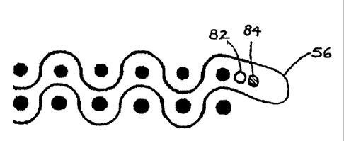
FIG. 10 is an enlarged schematic cross-sectional view of the seam loop
area of the flattened base fabric showing a rewoven continuous CD yam to
prevent yam migration in accordance with the present invention. To prevent
yarn migration, one embodiment of the present invention weaves a continuous
CD yam 82 across the width of the fabric along each edge of the ravel area.
When the fabric is folded and the seam loops are formed, this continuous CD
yarn 82 effectively blocks the unbound CD tail yarns from migrating into the
seam loops 56. Additional continuous CD yams 84 can also be woven into the
ravel area to impart desired characteristics to the fabric in the seam area.
For
example, a yam, yams, or string material may be added after the continuous CD
yarn to provide batting support in the seam area, among other things.
The present invention uses CD materials affixed along the edge(s) of the
ravel area to prevent yarn migration. The CD materials include continuous CD
yarns, CD yarn segments, CD strips of material, and other suitable materials
commonly used in the art. The materials may be affixed to the base fabric by
reweaving, sewing/stitching, stapling, gluing, melting, or any other suitable
technique known to those skilled in the art. For those embodiments involving
woven materials, the CD materials may be rewoven with higher/lower floats on
either side of the base fabric. In addition, various CD materials may be
affixed
in different sequences and/or patterns.
FIG. 11 is a plan view of the portion of the surface of the base fabric
layer similar to that shown in FIG. 5 showing reweaving of one or more
continuous CD yarns 55 into the fabric body without tails on both the roll and
sheet-side of the raveled area to prevent yam migration in accordance with the
present invention. Additionally, a Circumflex yarn 57 may be woven into the
16
CA 02566270 2006-11-08
WO 2005/113889
PCT/US2005/015562
body on one or both sides of the raveled area. This embodiment of the present
invention essentially uses the benefits of conventional woven technology to
reweave yams into the seam area of a multiaxial product. In order to prevent
the migration of CD tails while maintaining the desirable features inherent in
woven seamed products, the present invention re-weaves several yarns back
into the seam loop area of the multiaxial fabric. First, the raveled area is
made
wider than normal in order to accept additional CD materials. The width of the
ravel is easily controlled as understood by those skilled in the art. The new
ravel width may be any width desired to accept the seam enhancements of the
present invention. At a minimum, the ravel area is increased by at least the
width of two CD yarns, but this may be as many yam widths as desired. A shed
is then opened in the raveled area (the means of doing this are not considered
part of the invention and this may be done either by hand or be completely
mechanized across the full width of the fabric). Once the shed is opened, a
desired weave pattern is selected (which does not have to be the same pattern
as
the body weave in the seamed multiaxial base). For example, a two shed weave
in phase sequence with the last CD ends or tails may be used to insert two
continuous full width yams across the edges of the raveled area. Both yarns
are
inserted simultaneously and positioned to either side of the ravel. The
existing
CD tails cannot migrate past these woven in yams.
FIG. 12 is a top view of a multiaxial base fabric layer having low melt
yarns 120 sewn in a zigzag pattern into both sides of a raveled seam area to
prevent yam migration in accordance with an embodiment of the present
invention. "Low melt" is defined as a yarn having a component material with a
melting point lower than the polymer used in the fabric yams. The raveled area
is then folded over for the seam formation, stapling, and line sewing
processes.
When the entire fabric is heat-set to stabilize the fabric dimensions, the low
melt yams are fused together thereby holding the CD end yams and tails in
place. Alternatively, the sewn zigzag yarn can be ultrasonically spot welded
to
the fabric at various points.
Other embodiments of the invention may be applied after the seam has
been formed, stapled, and sewn along the alignment lines. As shown in FIG.
17
CA 02566270 2006-11-08
WO 2005/113889
PCT/US2005/015562
13, a yarn 130 may be blanket stitched along a seam loop edge of a multiaxial
base fabric layer to prevent yarn migration. Another embodiment of the present
invention, as shown in FIG. 14, is a yarn 140 stitched in a zigzag pattern
along
the seam loop edge of a multiaxial base fabric layer to prevent yarn
migration.
Further, yarn 130 in FIG. 13 and yarn 140 in FIG. 14 may be low melt yarns
similar to yarn 120 disclosed above in reference to FIG. 12.
Another embodiment of the invention is to insert a low melt nonwoven
strip 150 into the fold/raveled area of a multiaxial base fabric layer prior
to
heat-setting the seam loops to prevent yarn migration as shown in FIG. 15.
When the loops are heat set, the strip forms an adhesive which when cooled
holds the CD yarns in place, thereby preventing yam migration. Alternatively,
before the fabric is folded to form the seam, the low melt nonwoven strip 150
may be affixed (e.g. ironed or glued) onto one side of the raveled area, such
that
when the fabric is folded to form the seam loops the nonwoven strip is inside
the seamed area.
The yarn material may be any material desired that would reduce seam
wear, reduce seam popping or noise at the uhle box, and/or reduce seam plane
difference, to improve seaming times, etc. The yarn diameters may be less than
the CD body yarn diameters thereby reducing the plane difference imparted to
the seam. The yarns may also be of a much smaller diameter but with a
thermofusible sheath or layer of thermofusible fiber pre-attached, or be a
spun
yarn of thermofusible material, or simply be of a standard monofilament
material. These rewoven yarns can then be fused into place.
Any yarns added to prevent yarn migration, as taught herein, may be
inserted, woven, and/or sewn by hand or by machine as required. In addition,
these yarns may be added and/or stitched in numerous patterns including, but
not limited to, the zigzag and blanket stitch patterns disclosed herein.
If necessary, additional CD yarns can be inserted continuously on each
side of the ravel to produce any desired fabric properties or required width.
For
example, it may be desirable to insert another yarn as a Circumflex yam as
aforementioned to further reduce seam wear, marking and noise. This
18
CA 02566270 2006-11-08
WO 2005/113889
PCT/US2005/015562
Circumflex yarn is optional, but would be inserted in the same manner to
further improve the seamed product.
As mentioned previously, the improved seam may be produced to
ensure suitable uniform support for fiber batting material in the seam area.
This
may be accomplished through the addition of one or more additional yarns in
the raveled area. Essentially, the additional yarns act as a substitute for
the
different caliper and properties of the seam area resulting at least in part
from
the removal of the original CD body yarns to create the ravel. These yarns may
be any suitable combination of Circumflex and other type yarns. Further,
various stitching and other techniques may be used to secure the yarns.
Figures
16-23 show a number of exemplary suitable combinations in accordance with
the teachings of the present invention. Each figure shows a plan view of a
multiaxial base fabric layer having a vertical raveled seam area. In FIG. 16,
a
Circumflex yarn 160 is sewn into the raveled seam area and held in place by a
fine monofilament yarn 170 sewn in a zigzag pattern. Note the Circumflex yarn
may be positioned at any location between the edges of the raveled area. In
FIG. 17, the Circumflex yarn 160 is sewn into the edge of the raveled seam
area. FIG. 18 shows a thin monofilament or fine sheath/core yarn 180 straight
stitched into the raveled seam area. Again, this yarn may be positioned at any
location between the edges of the raveled area. FIG. 19 shows two different
yarns sewn into an edge of the raveled seam area by two rows of stitching 190.
The different yams may be of differing coarseness, size, and material. FIG. 20
shows two different yarns sewn into the raveled seam area and held in place by
one row of stitching sewn in a two-step zigzag pattern 200. FIG. 21 shows an
additional yarn sewn into an edge of the raveled seam area by a fine
monofilament using another stitching pattern 210. Any suitable type of
stitching may be used as deemed appropriate. In FIG. 22, two Circumflex yarns
are sewn on top of the raveled seam area and held in place by a monofilament
on the backside in a zigzag pattern using twin needles (not shown) in patterns
220. Similarly, FIG. 23 shows a Circumflex yarns sewn into the backside of the
vertical raveled seam area and held in place by a monofilament on the top and
bottom using twin needles in pattern 230.
19
CA 02566270 2006-11-08
WO 2005/113889
PCT/US2005/015562
The present invention not only prevents CD yam migration that impedes
seaming the fabric, but the width of the ravel area and weave pattern of the
inserted yams can be selected to impart diverse properties to the seam area
that
were not previously possible with multiaxial seamed products, but are often
inherent in woven seamed products. Hence, the present invention provides the
ability to combine the inherent advantages of a multiaxial base design with
the
inherent advantages of a woven seam fabric.
For example, thermofusible monofilament yams are often not desirable
as CD yams for a fabric body (especially before bonding) and sheath/core
thermofusible yam technology is also expensive. However, thermofusible or
adhesive activated yams can be both advantageous and cost effective when
introduced into the seam area before the loop heatset. The melting point of
these materials can be chosen so that these yams are not activated during the
loop heatset, but rather during the final curing when all CD ends are ready
for
bonding and fixing before cutting the seam and shipping the fabric to the
customer.
The fabric being woven to provide the on-machine-seamable base fabric
may be either single or multi-layer, and may be woven from monofilament,
plied monofilament or multifilament yams of a synthetic polymeric resin, such
as polyester or polyamide. The yams which form the seaming loops 56 and are
ultimately the lengthwise yams, are preferably monofilament yams.
The fabric according to the present invention comprises yams preferably
of polyester, polyamide, polybutylene terephthalate (PBT) or other polymers
known to those skilled in the art. Bicomponent or sheath/core yams can also be
employed. Any combination of polymers for any of the yams can be used as
identified by one of ordinary skill in the art. The CD and MD yams may have a
circular cross-sectional shape with one or more different diameters. Further,
in
addition to a circular cross-sectional shape, one or more of the CD, MD, or
rewoven/sewn-in yams may have other cross-sectional shapes such as a
rectangular cross-sectional shape or a non-round cross-sectional shape.
CA 02566270 2012-09-17
Application No. 2,566,270
Attorney Docket No. 17648-139
21