Note: Descriptions are shown in the official language in which they were submitted.
CA 02566359 2006-11-09
WO 2006/046969 PCT/US2005/016901
TURBINE CASE REINFORCEMENT
IN A GAS TURBINE JET ENGINE
By:
s L. James Cardarella, Jr.
CROSS REFERENCE TO RELATED APPLICATIONS
[0001] This application claims the benefit of U.S. Provisional Application No.
60/571,701, filed on May 17, 2004, titled "METHOD AND SYSTEM FOR IMPROVED
BLADE
TIP CLEARANCE IN A GAS TURBINE JET ENGINE.'
[0002] A nonprovisional U.S. application entitled "METHOD AND SYSTEM FOR
IMPROVED BLADE TIP CLEARANCE IN A GAS TURBINE JET ENGINE" is being filed
concurrently by L. James Cardarella, John Usherwood and Andres Del Campo,
wherein the
contributions by John Usherwood and Andres Del Campo have been assigned to
Carlton
Forge Works, a California corporation.
BACKGROUND
[0003] Since the development of the gas turbine jet engine, blade tip
clearance
within the interior of the casing has been a challenging problem. Blade tip
and inter-stage
sealing have taken on a prominent role in engine design since the late 1960's.
This is
because the clearance between the blade tips and surrounding casing tends to
vary due
primarily to changes in thermal and mechanical loads on the rotating and
stationary
structures. On today's largest land-based and aero turbine engines, the high
pressure turbine
case ("HPTC") and low pressure turbine case ("LPTC") have such large diameters
that they
are more susceptible to expanding excessively and becoming out-of-round,
exacerbating the
blade tip clearance problem.
[0004] Reduced clearance in both the HPTC and the LPTC can provide
dramatic reductions in specific fuel consumption ("SFC"), compressor stall
margin and engine
efficiency, as well as increased payload and mission range capabilities for
aero
. engines. Improved clearance management can dramatically improve engine
service life for
land-based engines and time-on-wing ("TOW') for aero engines. Deterioration of
exhaust gas
temperature ("EGT") margin is the primary reason for aircraft engine removal
from
service. The Federal Aviation Administration ("FAA") certifies every aircraft
engine with a
certain EGT limit. EGT is used to indicate how well the HPTC is performing.
Specifically,
EGT is used to estimate the disk temperature within the HPTC. As components
degrade and
clearance between the blade tips and the seal on the interior of the casing
increase, the
engine has to work harder (and therefore runs hotter) to develop the same
thrust. Once an
engine reaches its EGT limit, which is an indication that the high pressure
turbine disk is
reaching its upper temperature limit, the engine must be taken down for
-1-
CA 02566359 2006-11-09
WO 2006/046969 PCT/US2005/016901
maintenance. Maintenance costs for major overhauls of today's large commercial
gas turbine
jet engines can.easily exceed one million dollars.
BRIEF DESCRIPTION OF THE DRAWINGS
[0005] -
s FIG. I shows a schematic diagram of the overall structure of a typical gas
turbine jet engine.
FIG. 2 shows a sectional schematic diagram of a low pressure turbine case
of a typical gas turbine jet engine.
FIG. 3 shows a sectional schematic diagram of the low pressure turbine case
of FIG. 2 fitted with stiffener rings in an embodiment of the present
description.
FIG. 4 shows a sectional schematic diagram of Section A of the low pressure
turbine case of FIG. 3, showing the stiffener ring about to be seated in an
embodiment of the present description.
FIG. 5 shows a sectional schematic diagram of a section of a low pressure
turbine case showing the stiffener ring about to be seated in another
embodiment of
the present description.
FIG. 6 shows a sectional schematic diagram of a section of a low pressure
turbine case showing the stiffener ring seated in another embodiment of the
present
description.
FIG. 7 shows a sectional schematic diagram of a.section of a low pressure
turbine case showing the stiffener ring seated in another embodiment of the
present
description.
FIG. 8 shows an improvement in clearance under load in an embodiment of
the present description.
FIGS. 9A, 9B, and 9C show sectional schematic diagrams of a section of a
low pressure turbine case having the stiffener ring positioned on the low
pressure
turbine case with a hydraulic nut and secured with a locking nut in another
embodiment of the present description.
FIG. 10 shows a schematic diagram of a low pressure turbine case having
stiffener rings actuated by hydraulic, electric, or other means in another
embodiment
of the present description.
FIG. 11 shows a schematic cross-sectional diagram of a low pressure turbine
case having stiffener rings.
DETAILED DESCRIPTION OF THE DRAWINGS
[0006] Referring now to the Figures, in which like reference numerals and
names refer to structurally and/or functionally similar elements thereof,
Figure 1 shows a
schematic diagram of the overall structure of a typical gas turbine jet
engine. Referring now
to FIG. 1, Gas Turbine Jet Engine 100 has Fan 102 for air intake within Fan
Frame 104. High
Pressure Compressor Rotor 106 and its attached blades and stators force air
into Combustor
-2-
CA 02566359 2006-11-09
WO 2006/046969 PCT/US2005/016901
108, increasing the pressure and temperature of the inlet air. High Pressure
Turbine Rotor
110 and its accompanying blades and stators are housed within High Pressure
Turbine Case
112. Low Pressure Turbine Rotor 114 and its accompanying blades and stators
are housed
within Low Pressure Turbine Case 116. The turbine extracts the energy from the
high-
s pressure, high-velocity gas flowing from Combustor 108 and is transferred to
Low Pressure
Turbine Shaft 118.
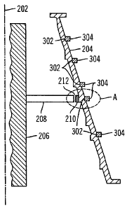
[0007] Figure 2 shows a sectional schematic diagram of a low pressure turbine
case of a typical gas turbine jet engine. Referring now to FIG. 2, Centerline
202 runs through
the center of Low Pressure Turbine Case 204 (shown in cross-section). Rotor
206 (shown in.
cross-section) has Blade 208 attached thereto and rotates on an axis of
rotation along
centerline 202. One skilled in the art will recognize that many more blades
and stators would
normally be present within Low Pressure Turbine Case 204. Only one Blade 208
is shown for
simplicity.
[0008] Labyrinth seal designs vary by application. Sometimes the labyrinth
is seals are located on the blade tips, and sometimes they are located on the
inside diameter of
the cases as shown in FIG. 2. Labyrinth Seals 210 (shown in cross-section)
line the inside
diameter of Low Pressure Turbine Case 204 forming a shroud around each
rotating Blade
208, limiting the air that spills over the tips of Blades 208. The shape of
Labyrinth Seals 210
is designed to create air turbulence between the tips of each Blade 208 and
the
corresponding Labyrinth Seal 210. The air turbulence acts as a barrier to
retard air from
escaping around the tips of Blades 208. It is appreciated that seals
performing similar
functions are often referred to by other names. Blade Tip Clearance 212,
defined as the
distance between the tip of Blade 208 and Labyrinth Seal 210, will vary over
the operating
points of the engine. The mechanisms behind Blade Tip Clearance 212 variations
come from
the displacement or distortion of both static and rotating components of the
engine due to a
number of loads on these components and expansion due to heat. Axis-symmetric
clearance
changes are due to uniform loading (centrifugal, thermal, internal pressure)
on the stationary
or rotating structures that create uniform radial displacement. Centrifugal
and thermal loads
are responsible for the largest radial variations in Blade Tip Clearance 212.
[0009] Wear mechanisms for Labyrinth Seal 210 can be generally categorized
into three major categories: rubbing (blade incursion), thermal fatigue, and
erosion. Engine
build clearances in both high pressure and low pressure turbine cases are
chosen to limit the
amount of blade rubbing. Studies have shown that improved blade tip clearances
in the high
pressure and low pressure turbine cases can result in significant life cycle
cost ("LCC")
reductions.
[00010] As a cold engine is started, a certain amount of Blade Tip Clearance
212
exists between each Labyrinth Seal 210 and the tip of Blades 208. Blade Tip
Clearance 212
is rapidly diminished as the engine speed is increased for takeoff due to the
centrifugal load
on Rotor 206 as well as the rapid heating of Blades 208, causing the rotating
components to
grow radially outward. Meanwhile, Low Pressure Turbine Case 204 expands due to
heafing
-3-
CA 02566359 2006-11-09
WO 2006/046969 PCT/US2005/016901
but at a slower rate. This phenomenon can produce a minimum Blade Tip
Clearance 212
"pinch point. As Low Pressure Turbine Case 204 expands due to heating after
the pinch
point, Blade Tip Clearance 212 increases. Shortly after Low Pressure Turbine
Case 204
expansion, Rotor 206 begins to heat up (at a slower rate than Low Pressure
Turbine Case
s 204 due to its mass) and Blade Tip Clearance 212 narrows. As the engine
approaches the
cruise condition, Low Pressure Turbine Case 204 and Rotor 206 reach thermal
equilibrium. .
and Blade Tip Clearance 212 remains relatively constant.
[00011] There can be tremendous benefit in narrowing Blade Tip Clearance 212
during the cruise condition. This is often where the greatest reduction in SFC
can be gained
(longest part of the flight profile). On the other hand, rubbing is generally
to be
avoided. Minimal clearance typically is maintained at takeoff to ensure thrust
generation as
well as keeping EGT below its established limit. Hence, it has been the goal
of many control
systems to attempt to maintain a minimal Blade Tip Clearance 212 while
avoiding rubbing
over the entire flight profile.
[00012] Engine temperatures generally play a large role in determining the
operational Blade Tip Clearances 212. Gas turbine performance, efficiency, and
life are
directly influenced by Blade Tip Clearances 212. Tighter Blade Tip Clearances
212 can
reduce air leakage over the tips of Blades 208. This can increase turbine
efficiency and
permit the engine to meet performance and thrust goals with less fuel burn and
lower rotor
inlet temperatures. Because the turbine runs at lower temperatures, while
producing the
same work, hot section components can have increased cycle life. The increased
cycle life of
hot section components can increase engine service life (TOW) by increasing
the time
between overhauls.
[00013] Engine SFC and EGT are generally directly related to HPTC blade tip
clearance. One study has shown that for every 0.001 inch increase in HPTC
blade tip
clearance, SFC increases approximately 0.1%, while EGT increases one C.
Therefore, it is
believed that a 0.010 inch HPTC blade tip clearance decrease may roughly
produce a one%
decrease in SFC and a ten C decrease in EGT. Military engines generally show
slightly
greater HPTC blade tip clearance influence on SFC and EGT due to their higher
operating
speeds and temperatures over large commercial engines. Improvements of this
magnitude
may produce large savings in annual fuel and engine maintenance costs
amounting to over
hundreds of millions of dollars per year.
[00014] Reducing fuel consumption may also reduce aero engine total
emissions. Recent estimates indicate that Americans alone now fly 764 million
trips per year
(2.85 airline trips per person). The energy used by commercial aircraft has
nearly doubled
over the last three decades. The increased fuel consumption accounts for
thirteen% of the
total transportation sector emissions of carbon dioxide (COZ). Modern aero
engine emissions
are made up of over seventy-one% COZ with about twenty-eight% water (H20) and
0.3%
nitrogen oxide (NO2) along with trace amounts of carbon monoxide (CO), sulfur
dioxide (SOz),
etc. Air transport accounts for 2.5% (600 million tons) of the world's COZ
-4-
CA 02566359 2006-11-09
WO 2006/046969 PCT/US2005/016901
Production. Emissions from land-based engines, primarily for power generation,
contributes
amounts in addition to these totals. Clearly a reduction in fuel burn can
significantly reduce
aero and land-based engine emissions.
[00015] Current large commercial engines have cycle lives (defined as the time
between overhauls) that vary significantly, ranging typically between 3,000 to
10,000
cycles. The cycle life is primarily determined by how long the engine retains
a positive EGT
margin. New engines or newly overhauled engines are shipped with a certain
cold build
blade tip clearance which increases with time. As the engine operating
clearances increase,
the engine generally works harder (hotter) to produce the same work and is
therefore less
to efficient This increase in operating temperature, particularly takeoff EGT,
can further
promote the degradation of hot section components due to thermal fatigue. It
is believed that
retaining engine takeoff EGT margin by maintaining tight blade tip clearances
can
dramatically increase engine cycle life. This could also lead to huge savings
in engine
maintenance over a period of years due to the large overhaul costs.
[00016] Previous attempts at blade tip clearance management can generally be
categorized by two control schemes, active clearance control ("ACC") and
passive ciearance
control ("PCC"). PCC is defined as any system that sets the desired clearance
at one
operating point, namely the most severe transient condition (e.g., takeoff, re-
burst, maneuver,
etc.). ACC, on the other hand, is defined as any system that allows
independent setting of a
desired blade tip clearance at more than one operating point. The problem with
PCC systems
is that the minimum clearance, the pinch point, that the system must
accommodate often
leaves an undesired larger clearance during the much longer, steady state
portion of the flight
(i.e., cruise).
[00017] Typical PCC systems include better matching of rotor and stator growth
throughout the flight profile, the use of abradables to limit blade tip wear,
the use of stiffer
materials and machining techniques to limit or create distortion of static
components to
maintain or improve shroud roundness at extreme conditions, and the like.
Engine
manufacturers began using thermal ACC systems in the late 1970's and early
1980's. These
systems utilized fan air to cool the support flanges of the HPTC, reducing the
case and
3o shroud diameters, and hence blade tip clearance, during cruise conditions.
[00018] It is believed that all of the approaches described above have
significant
problems associated with them. Some are quite expensive, others achieve little
results,
especially during cruise where the greatest advantages are gained, or require
actuation
through the case due to the lack of current high temperature actuator
capabilities, which raise
secondary sealing issues and added weight and mechanical complexity.
[00019] Figure 3 shows a sectional schematic diagram of the low pressure
turbine case of FIG. 2 fitted with stiffener rings in an embodiment of the
present
description. Figure 11 shows a cross-sectional schematic diagram of the low
pressure
turbine case of FIG. 2 fitted with stiffener rings in an embodiment of the
present
description. Referring now to FIGs. 3, 11, one or more features of the present
description
-5-
CA 02566359 2006-11-09
WO 2006/046969 PCT/US2005/016901
may be applied to existing gas turbine jet engines, or may be incorporated
into the design and
build of new gas turbine jet engines, for a variety of applications including
aviation, marine
and land-based engines. Features of the present description are applicable to
the HPTC as
well as the LPTC, and the description and figures in relation to the LPTC also
apply equally to
the HPTC and are not limited to the LPTC.
[00020] Notches 302, which may be of several different geometries as described
in detail below, are manufactured circumferentially, typically through
machining, into the
outside diameter of Low Pressure Turbine Case 204 to coincide with one or more
locations of
the Labyrinth Seals 210. In addition to locations corresponding to one or more
of the
locations of the Labyrinth Seals 210, notches may be machined
circumferentially in locations
corresponding to "hot spots" that have been identified in Low Pressure Turbine
Case 204
through computer modeling, through monitoring surface temperatures, or through
visual
inspections for cracks when the engine is overhauled. For existing engines,
Low Pressure
Turbine Case 204 is typically removed in order to repair cracks resulting from
the these "hot
is spots". After such repairs, groves may then be applied through a weld
repair through
machining. The external rings would then be shrink interference fit in the
grooves. It is
appreciated that the stiffener rings may be located at other positions of a
turbine case,
depending upon the particular application It is further appreciated that
sizes, dimensions,
shapes, materials and clearances may vary, depending upon the particular
application.
[00021] In one embodiment, Stiffener Rings 304 (shown in cross section in FIG.
3) are shrink interference fit into each Notch 302 so that the Stiffener ring
304 encircles the
circumferential Notch 302 as shown in FIG. 11. Since Low Pressure Turbine Case
204 is
conical in shape, each Stiffener Ring 304 may have a different diameter. In
each case, the
inside diameter of each Stiffener Ring 304 may be slightly less than the
outside diameter of its
corresponding Notch 302. Each Stiffener Ring 304 is heated, starting with the
largest
diameter Stiffener Ring 304. Heating causes each Stiffener Ring 304 to expand,
increasing
the inside diameter to a diameter that is greater than the outside diameter of
its corresponding
Notch 302. Once positioned in Notch 302, Stiffener Ring 304 is allowed to
cool, which shrinks
with an interference fit into its corresponding Notch 302.
[00022] Figure 4 shows a sectional schematic diagram of Section A of the low
pressure turbine case of FIG. 3, showing the stiffener ring about to be seated
in an
embodiment of the present description. Referring now to FIG. 4, Notch 302 is
manufactured
circumferentially with a reverse taper relative to the taper of the low
pressure turbine case in
one embodiment. Angle 402 for the taper will vary from case to case, ranging
from just
greater than 0 for a cylindricaf case to an appropriate degree that would
depend upon the
specific geometry of a conical case. Stiffener Ring 304 may be machined
circumferentially on
its inside diameter to match this same taper. Even though Stiffener Ring 304
is shrink
interference fit onto Low Pressure Turbine Case 204, the taper can add extra
security so that
Stiffener Ring 304 is inhibited from slipping axially on Low Pressure Turbine
Case 204. If
Notch 302 was manufactured flat without the taper, there may be an increased
possibility of
-6-
CA 02566359 2006-11-09
WO 2006/046969 PCT/US2005/016901
slippage in some applications. When Stiffener Ring 304 has been heated it
expands, giving
rise to Ring Clearance 404, enabling Stiffener Ring 304 to be positioned as
shown against
Heel 406 of Notch 302. As Stiffener Ring 304 cools, it shrinks in diameter and
seats itself
circumferentially into Notch 302. At ambient temperature, due to the smaller
diameter of the
s inner surface of the Stiffener Ring 304 to the diameter of the outer surface
of the Notch 302, a
shrink with an interference fit results, with radially compressive
circumferential force being
applied to Low Pressure Turbine Case 204 by Stiffener Ring 304, and tensile
circumferential
force is applied to Stiffener Ring 304 by Low Pressure Turbine Case 204. In
one
embodiment, the radially compressive forces may be centered on the axis of
rotation defined
io by center line 202 as schematically shown by arrows in FIG. 11. In one
embodiment, the
radially compressive forces are applied continuously around the entire
circumference of the
Notch 302 and the Turbine Case 204 without interruption.
[00023] In one example, Low Pressure Turbine Case 204 may be fifty inches in
outside diameter at the portion where Blade 208 and Labyrinth Seal 210 are
located. In one
is embodiment, the Stiffener Ring 304 may be fabricated as a solid, unitary or
one-piece,
continuous or seamless member forged or machined in a closed loop shape. In
another
embodiment, the Stiffener Ring 304 may be fabricated using an open loop-shaped
member
and bonding the ends together by welding, for example, to form a closed loop
shape. Low
Pressure Turbine Case 204 is made of nickel-based super alloy, such as Inconel
718, as is
20 Stiffener Ring 304 through a forging process. Super alloy Inconel 718 is a
high-strength,
complex alloy that resists high temperatures and severe mechanical stress
while exhibiting
high surface stability, and is often used in gas turbine jet engines. It is
appreciated that the
stiffener ring and the turbine case may be made of a variety of materials,
depending upon the
particular application. Heating Stiffener Ring 304 to a calculated temperature
will cause
25 Stiffener Ring 304 to expand, yielding an appropriate Ring Clearance 404
when Low Pressure
Turbine Case 204 is at ambient air temperature of approximately seventy F.
Alternatively,
Low Pressure Turbine Case 204 may be cooled with liquid nitrogen or other
means to a
calculated temperature to cause Low Pressure Turbine Case 204 to shrink in
diameter,
yielding an appropriate Ring Clearance 404 when Stiffener Ring 304 is at
ambient air
30 temperature of approximately seventy F. Alternatively, an appropriate Ring
Clearance 404
may be achieved through a combination of cooling Low Pressure Turbine Case 204
and
heating Stiffener Ring 304, each to various calculated temperatures.
Increasing or
decreasing the inside diameter of Stiffener Ring 304 will result in more or
less radially
compressive circumferential force and tensile stress as required for a
particular application,
35 and within the stress limits of the material that Stiffener Ring 304 is
made from.
[00024] In addition, the machining for Low Pressure Turbine Case 204 may be
done in a first direction, such as radially, and the machining for Stiffener
Ring 304 may be
done in a second direction, such as axially, which is more or less
perpendicular to the first
direction. Since machining leaves a spiral, or record, continuous groove on
the machined
40 surfaces, the grooves on each surface will align in a cross-hatch manner to
each other,
-7-
CA 02566359 2006-11-09
WO 2006/046969 PCT/US2005/016901
increasing the frictional forces between the two surfaces and reducing the
potential for
movement of Stiffener Ring 304 within Notch 302, including axial or rotational
movement. The plurality of grooves on Stiffener Ring 304, which may be made of
a nickel-
base super alloy for example, may be harder than the plurality of grooves on
Notch 302 of
s Low Pressure Turbine Case 204, which is typically made of titanium, or in
other low pressure
turbine casings, possibly steel or aluminum. The nickel-base super alloy
grooves can dent
into or form an indentation in the softer titanium, steel, or aluminum
grooves. Alternatively,
Stiffener Ring 304 may simply be spot welded in one or more locations to Notch
302, or
bolted to one or more flanges secured to Notch 302, to keep Stiffener Ring 304
from spinning
or otherwise moving in relation to Notch 302. Machining in cross directions
may not be
needed in this case.
[00025] By thus positioning Stiffener Rings 304 in the manner described, Blade
Tip Clearance 212 may be improved in some applications, especially during
cruise operation
of the engine in some applications. An engine designer may as a result, design
the engine to
have a reduced blade tip clearance than may otherwise be appropriate for a
given engine
design absent such stiffener rings. It is also appreciated that other or
different benefits,
advantages, improvements or other features may be utilized alone or in
combination,
depending upon the particular application. In one application, the radially
compressive
circumferential force (represented by arrows in FIG. 11) applied by the
Stiffener Rings 304
can prevent Low Pressure Turbine Case 204 from expanding due to heat as much
as it would
otherwise expand. In one aspect, the Stiffener Rings 304 function as a girdle
for the Turbine
Case 204, to inhibit expansion or going out of round and otherwise reinforce
the Turbine Case
204. Stiffener Rings 304 may be made of the same material as Low Pressure
Turbine Case
204, or may be made of a different material with a lower coefficient of
thermal expansion,
which would increase the radially compressive circumferential force applied
over that of a
stiffener ring of the same material as the case as the temperature rises. The
compressive
forces may be sufficient to form an indentation in the turbine case such as in
the Notch 302.
[00026] In many engine designs, heat is mainly dissipated from the outside
surface area of Low Pressure Turbine Case 204 by convection. Another benefit
which may
be achieved by adding Stiffener Rings 304 to Low Pressure Turbine Case 204 is
that heat
may be dissipated at a greater rate because Stiffener Rings 304 can act as
cooling fins, which
can result in cooler operating temperatures within Low Pressure Turbine Case
204. This
cooling may also contribute to less expansion and smaller Blade Tip Clearance
212. Also,
Stiffener Rings 304 can help to maintain roundness of Low Pressure Turbine
Case 204.
Again, it is appreciated that other or different benefits, advantages,
improvements or other
features may be utilized alone or in combination, depending upon the
particular application.
[00027] Figure 5 shows a sectional schematic diagram of a section of a lauv
pressure turbine case showing the stiffener ring about to be seated in another
embodiment of
present description. Referring now to FIG. 5, Notch 502 is machined
circumferentially with a
chevron shape in one embodiment. Angle 508 may vary by application. Stiffener
Ring 504 is
-8-
CA 02566359 2006-11-09
WO 2006/046969 PCT/US2005/016901
machined circumferentially on its inside diameter to match this same chevron
shape. Even
though Stiffener Ring 504 is shrink interference fit onto Low Pressure Turbine
Case 204, the
chevron shape can add extra security to inhibit the Stiffener Ring 304 from
slipping off of Low
Pressure Turbine Case 204. When Stiffener Ring 504 has been heated it expands,
giving
rise to Ring Clearance 404, enabiing Stiffener Ring 504 to be positioned as
shown against
Heel 506 of Notch 502. As Stiffener Ring 504 cools, it shrinks in diameter and
seats itself
circumferentially into Notch 502. At ambient temperature, due to the smaller
inside diameter
of Stiffener Ring 504 to the outside diameter of Notch 502, a shrink with an
interference fit
results, with radially compressive circumferential force being applied to Low
Pressure Turbine
io Case 204 by Stiffener Ring 504, and tensile circumferential force is
applied to Stiffener Ring
504 by Low Pressure Turbine Case 204.
[00028] Figure 6 shows a sectional schematic diagram of a section of a low
pressure turbine case showing the stiffener ring seated in another embodiment
of the present
description. Referring now to FIG. 6, for aero applications, where added
weight to the engine
is a concern, Stiffener Ring 604 is manufactured to have a profile that, when
seated as shown
in FIG:6, is substantially flush with the outer surface of Low Pressure
Turbine Case
204. Notch 302 with a reverse taper as shown in FIG. 4 is machined into Low
Pressure
Turbine Case 204. In addition, based on the engine to be designed or to be
retrofitted, Notch
302 may be machined deeper, and/or wider, and Stiffener Ring 604 given added
depth,
and/or width, in order to meet the radially compressive and tensile
circumferential stress
requirements.
[00029] Figure 7 shows a sectional schematic diagram of a section of a low
pressure turbine case showing the stiffener ring seated in another embodiment
of the present
description. Referring now to FIG. 7, for aero applications, where added
weight to the engine
is a concern, Stiffener Ring 704 is manufactured to have a profile that, when
seated as shown
in FIG.6, is substantially flush with the outer surface of Low Pressure
Turbine Case
204. Notch 502 with a chevron shape as shown in FIG. 5 is machined into Low
Pressure
Turbine Case 204. In addition, based on the engine to be designed or to be
retrofitted, Notch
502 may be machined deeper and/or wider, and Stiffener Ring 704 given added
depth, and/or
width, in order to meet the radially compressive and tensile stress
requirements. In addition
to aero or aviation applications, it is appreciated that flush embodiments as
well as other
embodiments may be utilized in land-based and marine applications as well.
[00030] One skilled in the art will recognize that, in addition to the reverse
taper
and chevron designs for the notch and stiffener ring as shown in FIGS. 4-7,
various other
designs may be utilized to accomplish the same or similar or different goals.
For example,
the notch may have one or more ridges and channels, angular or undulating,
that will match
up with one or more channels and ridges, angular or undulating, on the inside
surface of the
stiffener ring. Alternatively, the notch and stiffener ring may have an
inverted chevron
shape. In other embodiments, a notch may not be utilized. Many other such
shapes may be
envisioned without departing from the scope of the present description.
-9-
CA 02566359 2006-11-09
WO 2006/046969 PCT/US2005/016901
(00031] Figure 8 shows the improvement in blade tip clearance under load in an
embodiment of the present description. Referring now to FIG. 8, Stiffener,Ring
304 as shown
in FIG. 4 has been shrink interference fit onto Low Pressure Turbine Case 204,
and the
engine is now under load, such as during cruise operation. Labyrinth Seal 210
and Low
Pressure Turbine Case 204 with Inner Surface 802 and Outer Surface 804 are
depicted with
solid lines in the positions they would be in without Stiffener Ring 304. Low
Pressure Turbine
Case 204 would have expanded in diameter, and Labyrinth Seal 210 would have
moved
away from Blade 208, giving rise to a wider Blade Tip Clearance 212. However,
due to the
radially compressive force exerted by Stiffener Ring 304 on Low Pressure
Turbine Case 204,
Labyrinth Seal 210 is in the position indicated in phantom as 210', and Ring
304, Inner
Surface 802 and Outer Surface 804 of Low Pressure Turbine Case 204 are in the
positions
indicated in phantom as 304', 802', and 804', thus reducing Blade Tip
Clearance 212'.
(00032] Thus, in one aspect of the present description, the amount of
expansion
that would normally occur due to heating in the LPTC and the HPTC, is reduced,
and
is consequenUy blade tip clearance may be improved. As stated above, increased
blade tip
clearance can accelerate the effects of low cycle fatigue and erosion due to
increased
temperatures in the HPTC and LPTC, and degrade EGT margin and engine life. In
general,
for large gas turbine engines, it is believed that blade tip clearance
reductions on the order of
0.010 inch can produce decreases in SFC of one% and EGT of ten C. It is
believed that
improved blade tip clearance of this magnitude can produce fuel and
maintenance savings of
over hundreds of millions of dollars per year. Reduced fuel burn can also
reduce aircraft
emissions, which currently account for thirteen % of the total U.S.
transportation sector
emissions of COZ. In another aspect, blade tip clearances can be reduced at
cruise condition
to make a significant impact on SFC and EGT margin and improve turbine
2s efficiency. Moreover, the increased outer surface area of the HPTC and LPTC
due to the
stiffener rings can, in certain embodiments, increase cooling and result in
lower internal
temperatures which can lengthen the cycle life of the engine. In yet another
aspect, an
increase in payload per engine may be achieved due to the improvement in blade
tip
clearance. Additional pounds of freight may be transported per takeoff and
landing. It is
further appreciated that features of the present description could readily
replace expensive
passive clearance control options. It is appreciated that reductions in one or
more of out-of-
roundness, blade tip clearance, SFC, EGT or pollu6ng emissions may be achieved
utilizing
one or more features herein described. For example, fabricating a stiffener
ring from a
material having a lower coefficient of thermal expansion than that of the
turbine case material,
may facilitate achieving one or more of these or other reductions. Similarly,
it is appreciated
that one or more of these reductions or other benefits may be achieved
fabricating a turbine
case and stiffener ring of the same material.
[00033] FIGS. 9A, 98, and 9C show sectional schematic diagrams of a section of
a low pressure turbine case having the stiffener ring positioned on the low
pressure turbine
4o case with a hydraulic nut and secured with a locking nut in another
embodiment. Referring
-10-
CA 02566359 2006-11-09
WO 2006/046969 PCT/US2005/016901
now to FIG. 9A, Stiffener Ring 904 is sized to fit without pressure in a
location near an internal
Blade 208 and Labyrinth Seal 210, or previously identified "hot spot", and
placed in position
there. Next, a Hydraulic Nut 902 is threadably mounted to Low Pressure Turbine
Case
204. Hydraulic Nut 902 has Piston 906 which engages with Stiffener Ring 904.
[00034] In FIG. 9B, Piston 906 has extended from Hydraulic Nut 902, pushing
Stiffener Ring 904 toward the larger diameter end of Low Pressure Turbine Case
204, thus
positioning Stiffener Ring 904 in the optimum location in relation to the
internal Blade 208 and
Labyrinth Seal 210 and resulting in an interference fit. The, amount that
Piston 906 is
extended by Hydraulic Nut 902 is calculated to produce a desired compressive
circumferential
io force by Stiffener Ring 904.
[00035] In FIG. 9C, Hydraulic Nut 902 has been removed, and Locking Nut 908
has been threadably attached in its place onto Low Pressure Turbine Case 204.
Retainer
910 of Locking Nut 908 engages with Stiffener Ring 904, thus securing
Stiffener Ring 904 in
place. This process is repeated for as many stages as required based upon
turbine
is design. This embodiment may add excessive weight and would most likely be
best suited for
land based applications where weight is not of such concem.
[00036] FIG. 10 shows a schematic diagram of a low pressure turbine case
having stiffener rings actuated by hydraulic, electric, or other means in
another embodiment
of the present description. Referring now to FIG. 10, Low Pressure Turbine
Case 1000 has
20 Stiffener C-Rings 1004 positioned at predetermined locations to coincide
with blade/labyrinth
seals and/or "hot spots". In this embodiment, Stiffener C-Rings 1004 are not
shrink
interference fit onto Low Pressure Turbine Case 1000. A notch for each
Stiffener C-Ring
1004 may still be machined into Low Pressure Turbine Case 1000, but the
stiffener rings are
c-rings rather than continuous rings. Each end of Stiffener C-Ring 1004 is
linked to an
25 Actuator Means 1002, which when actuated, pulls each end of Stiffener C-
Ring 1004
together, exerting compressive force including radially compressive force on
Low Pressure
Turbine Case 1000. The inside surface of each Stiffener C-Ring 1004, or the
notch surface,
or both, may be coated with Teflon or some other lubricating substance to
facilitate slippage
when tightened.
30 [00037] Each Actuator Means 1002 is connected to Controller 1008 through
Electrical/Electronic Connections 1006. Controller 1008 receives temperature
readings from
multiple temperature sensors located near each Stiffener C-Ring 1004 (not
shown). It is also
possible to derive the LPTC temperature from EGT temperature readings and use
these
readings for feedback to Controllers 1008, As the temperatures being monitored
throughout
35 Low Pressure Turbine Case 1000 rise, Controller 1008 processes the
temperature data and
determines how much each of the ends of each Stiffener C-Ring 1004 need to be
pulled
together by each Actuator Means 1002 in order to exert the proper compressive
circumferential force on Low Pressure Turbine Case 1000 to provide a suitable
benefit such
as maintaining an optimum blade tip clearance or counterbalancing a "hot
spot", for example.
-11-
CA 02566359 2006-11-09
WO 2006/046969 PCT/US2005/016901
[00038] In an altemate embodiment, instead of a oaring, a chain-like multiple
segmented ring may be coupled together by Actuator Means 1002. In another
embodiment,
the stiffener rings may be made of a strip of non-metallic material, such as
Kevlar . The
inside surface of the Kevlar , or the notch surface, or both may also be
coated with Teflon
or some other lubricating substance to facilitate slippage when tightened.
[00039] Having described various features, it will be understood by those
skilled
in the art that many and widely differing embodiments and applications will
suggest
themselves without departing from the scope of the present description.
-12-