Language selection

Search

Patent 2566385 Summary

Third-party information liability

Some of the information on this Web page has been provided by external sources. The Government of Canada is not responsible for the accuracy, reliability or currency of the information supplied by external sources. Users wishing to rely upon this information should consult directly with the source of the information. Content provided by external sources is not subject to official languages, privacy and accessibility requirements.

Claims and Abstract availability

Any discrepancies in the text and image of the Claims and Abstract are due to differing posting times. Text of the Claims and Abstract are posted:

  • At the time the application is open to public inspection;
  • At the time of issue of the patent (grant).
(12) Patent: (11) CA 2566385
(54) English Title: ASSEMBLY TO MOUNT A HYDRANT ON A ROOF
(54) French Title: ENSEMBLE D'INSTALLATION D'UNE PRISE D'INCENDIE SUR UN TOIT
Status: Granted
Bibliographic Data
(51) International Patent Classification (IPC):
  • E03B 9/02 (2006.01)
(72) Inventors :
  • BALL, WILLIAM T. (United States of America)
(73) Owners :
  • WCM INDUSTRIES, INC. (United States of America)
(71) Applicants :
  • WCM INDUSTRIES, INC. (United States of America)
(74) Agent: RICHES, MCKENZIE & HERBERT LLP
(74) Associate agent:
(45) Issued: 2008-10-28
(22) Filed Date: 2006-11-01
(41) Open to Public Inspection: 2007-05-01
Examination requested: 2006-11-01
Availability of licence: N/A
(25) Language of filing: English

Patent Cooperation Treaty (PCT): No

(30) Application Priority Data:
Application No. Country/Territory Date
60/596,962 United States of America 2005-11-01
11/554,232 United States of America 2006-10-30

Abstracts

English Abstract

An assembly for mounting a hydrant to a roof. The assembly includes a housing that is adapted to fit about a standpipe that is disposed through a roof top. The assembly additionally has a sealing member that is positioned between the housing and the standpipe and a mounting plate that is connected to the housing to mount the hydrant to the roof.


French Abstract

Un ensemble d'installation d'une prise d'incendie sur un toit. L'ensemble comprend un boîtier qui est adapté pour s'ajuster autour d'un tube vertical qui est disposé à travers un toit. L'ensemble comporte en outre un élément d'étanchéité qui est positionné entre le boîtier et le tube vertical et une plaque de montage qui est reliée au boîtier pour monter la prise d'incendie sur le toit.

Claims

Note: Claims are shown in the official language in which they were submitted.


What is claimed:


1. An assembly for mounting a hydrant to a roof,
comprising:
a housing adapted to fit about a standpipe of the hydrant;
a sealing member positioned between the housing and the
standpipe; and
a mounting plate connected to at least a portion of the
housing for securing the hydrant to the roof.

2. The assembly of claim 1 wherein the housing has a base
plate and a support section.

3. The assembly of claim 2 wherein the base plate and the
support section have openings in spaced alignment.

4. The assembly of claim 1 wherein a base plate is
connected to a lower surface of the mounting plate.

5. The assembly of claim 1 wherein the housing has at
least a pair of flashing sections.

6. The assembly of claim 5 wherein the pair of flashing
sections have flanges that receive bolts that secure the
assembly to the roof.

7. The assembly of claim 1 wherein a clamp is used with a
compression ring to secure the housing to the standpipe.

8. The assembly of claim 1 wherein a compression ring and
a compression nut are used to secure the housing to the
standpipe.

6


9. The assembly of claim 1 wherein a compression bolt and
a compression nut are used to secure the housing to the
standpipe.

10. An assembly for mounting a hydrant to a roof, comprising:
a housing having a support section that is associated with a
base plate, said support section being adapted to fit about a
standpipe of the hydrant;

a sealing member positioned between the housing and the
standpipe; and

a mounting plate connected to at least a portion of the
housing for securing the hydrant to the roof.

1 1. The assembly of claim 10 wherein said base plate and said
support section have openings in spaced alignment.

12. The assembly of claim 10 further comprising a second base
plate that is positioned beneath said mounting plate and associated
with said base plate of said housing wherein said base plate and said
second base plate cooperate to secure the hydrant.

13. The assembly of claim 10 wherein said housing has at least a
pair of flashing sections.

14. The assembly of claim 13 wherein said pair of flashing
sections have flanges that receive bolts that secure the assembly to
the roof

7


15. The assembly of claim 10 wherein a clamp is used with a
compression ring to secure said housing to the standpipe.

16. The assembly of claim 10 wherein a compression ring and a
compression nut are used to secure said housing to the standpipe.
17. The assembly of claim 10 wherein a compression bolt and a
compression nut are used to secure said housing to the standpipe.
18. An assembly for mounting a hydrant to a roof, comprising:

a support section with an upper opening that is adapted to
interface with a standpipe of the hydrant;

a base plate associated with a lower edge of said support
section; and

a second plate that cooperates with said base plate to
fixedly secure the standpipe.

19. The assembly of claim 18 wherein said support section is
conical.

20. The assembly of claim 18 wherein said support section is
made of at least two halves.

21. The assembly of claim 18 wherein said second base plate
8


extends within said support section and includes a lower opening
that is adapted to interface with the standpipe.

22. The assembly of claim 18 further including a mounting plate
that is adapted to rest on the roof, said mounting plate being
adapted for interconnection with said base plate.

23. A roof-mounted hydrant, comprising:

a hydrant having a standpipe adapted for association with a
building surface;

a means for supporting having an upper opening that
engages the standpipe;

a means for securing interconnected to said means for
supporting, said means for securing adapted for interconnection to
the building surface; and

a second means for securing positioned beneath said
building surface that cooperates with said means for supporting.
24. The roof-mounted hydrant of claim 23 further comprising a
mounting plate positioned below said means for securing wherein
said means for securing is interconnected thereto.

25. The roof-mounted hydrant of claim 23 wherein said means for
supporting is interconnected to said standpipe with at least one
means for sealing.

26. The roof-mounted hydrant of claim 23 wherein said means for
9


supporting is conical.

27. The roof-mounted hydrant of claim 23 wherein said means for
supporting is made of at least two halves.

28. The roof-mounted hydrant of claim 23 wherein said second
means for supporting extends within said means for supporting and
includes a lower opening that is adapted to interface with the
standpipe.


Description

Note: Descriptions are shown in the official language in which they were submitted.


CA 02566385 2008-03-31

TITLE: ASSEMBLY TO MOUNT A HYDRANT TO A ROOF
BACKGROUND OF THE INVENTION
This invention is directed to a mounting assembly for a
hydrant, and more particularly to an assembly for mounting a
yard hydrant to a roof.
Hydrants are sometimes installed on the roof of a
building for cleaning purposes such as washing condenser or
air conditioning coils. To mount the hydrant, different
makeshift devices have been used. For example, bollards
have been installed and then the hydrant is secured to the
roof. Alternatively, a hydrant has been attached to a
plastic shift box that is tarred over. Neither of these
approaches provides a stable connection that also prevents
water leakage. Accordingly, there is a need in the art for
a mounting assembly that addresses these problems.
Therefore, a principal object of the present invention
is to provide an assembly to mount a hydrant to a roof that
minimizes leakage, provides support and is easy to install.
These and other objects, features, or advantages of the
present invention will become apparent from the
specification and claims.

SUMMARY OF THE INVENTION
An assembly for mounting a hydrant to a roof having a
housing that fits about a standpipe of the hydrant.
Positioned between the housing and the standpipe is a
sealing member. The housing is connected to a mounting

1


CA 02566385 2008-03-31

plate that is adapted to be connected to the roof of a
building.

In one aspect of the invention there is provided an
assembly for mounting a hydrant to a roof, comprising: a
housing having a support section that is associated with
a base plate, said support section being adapted to fit
about a standpipe of the hydrant; a sealing member
positioned between the housing and the standpipe; and a
mounting plate connected to at least a portion of the
housing for securing the hydrant to the roof.

In a further aspect of the invention there is
provided an assembly for mounting a hydrant to a
roof, comprising: a support section with an upper
opening that is adapted to interface with a standpipe of
the hydrant; a base plate associated with a lower edge of
said support section; and a second plate that cooperates
with said base plate to fixedly secure the standpipe.

In yet a further aspect of the invention there is
provided a roof-mounted hydrant, comprising: a
hydrant having a standpipe adapted for association with a
building surface; a means for supporting having an upper
opening that engages the standpipe; a means for securing
interconnected to said means for supporting, said means
for securing adapted for interconnection to the building
surface; and a second means for securing positioned
beneath said building surface that cooperates with said
means for supporting.

BRIEF DESCRIPTION OF DRAWINGS

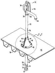
Fig. 1 is a side view of a mounting assembly and a
hydrant;

Fig. 2 is a partial perspective view of a mounting
2


CA 02566385 2008-03-31
assembly;

Fig. 3 is an exploded perspective view of a
mounting assembly;

Fig. 4 is a sectional view of a mounting
assembly;

Fig. 5 is a sectional view of a mounting
assembly;

Fig. 6 is a sectional view of a mounting
assembly;

Fig. 7 is a perspective view of a mounting
assembly;

and

Fig. 8 is a sectional view of the mounting
assembly of Fig. 7.

DETAILED DESCRIPTION OF THE PREFERRED EMBODIMENTS
Generally, a yard hydrant 10 has a valve body
12, a valve seat 14, possibly a drain port or hole
16, an inlet 18 which is connected to a source of
pressurized water (not shown) and an outlet 20 at
its top. Connected at one end to the valve body 12
is a standpipe 22 that extends vertically and is
connected to a head casting 24 at the opposite end.

The head casting 24 has an inlet 26 coupled to
the standpipe 22 and a discharge conduit or outlet
28 that preferably extends downwardly and outwardly
from the head casting 24 and a fluid conduit 30 that
extends between the inlet 26 and the outlet 28.

Disposed within the valve body 12 is a closure
valve plunger 32 that is connected to a valve stem
or actuator rod

2a


CA 02566385 2006-11-01

34 that extends from the closure valve 32 through the
standpipe 22 and is connected to an actuator device 36
attached to the head casting 24 such as a lever or handle.
The hydrant has been described by example only, as other
types of hydrants may be used without departing from the
scope of the invention.
The hydrant 10 is secured to the roof 38 with a
mounting assembly 40. The mounting assembly 40 can be of
any shape and size, and is comprised of a one piece or
multiple piece housing 42. Alternatively, the housing is
formed by two or more cast iron flashing sections 44. The
housing 42 has a base plate 46 and a support section 48.
For the two piece housing 42 the inner surface 50 of each
section 44 is formed to mirror the inner surface of the
other section for connection by any conventional manner such
as a nut and bolt or by a weld. In one example, the
flashing sections 44 have a flange 45 that extends outwardly
as shown in Figs. 1-3 for receiving connecting bolts 64.
Alternatively, as shown in Figs. 7-8, the connecting flange
45 extends inwardly and receives the connecting bolts 64.
Other devices may also be used to support the hydrant and
prevent leakage. For example, as shown in Fig. 4, a metal
clamp 65 is used with a compression ring 67 to secure the
housing 42. Fig. 5 shows the use of a compression nut 69 to
secure the housing 42. Also, as shown in Fig. 6,
compression bolts 71 may be used to secure and seal the
housing 42.
At an end 52 of the support section 48 is an opening 54
formed to receive a standpipe 22. Similarly, the base plate
48 has an opening 56 that is in spaced alignment with
opening 54 and also formed to fit around the standpipe 22.
Positioned between the flashing sections 44 are sealing
3


CA 02566385 2006-11-01

members 58. For example, between the inner surface 50 of
each section 44 are sealing members 58. Also, positioned
within openings 54 and 56 are pipe seal halves 60.
Additionally, a sealing ring may be used in place of the
seal halves 60. The gasket 58 and seal halves 60 create a
seal around standpipe 22 to prevent leakage toward the roof.
The base plate 46 is connected to a generally flat
mounting plate 62 having a central opening 63 by any
conventional means such as by a plurality of nuts and bolts
64 that extend through connecting apertures.
In an alternative embodiment, a second base plate 68 is
positioned on a lower surface 70 of the mounting plate 62.
The second base plate 68 has a plurality of connecting
apertures 66 that align with the apertures 66 of base plate
46 to receive bolts 64.

To install, the valve body 12 of the hydrant 10 is
connected to a source of pressurized water (not shown). The
standpipe 22 is connected to the valve body 12 and extends
through an opening in the roof. The mounting plate 62 is
placed over the standpipe 22 such that the standpipe 22
extends through opening 63. The flashing sections 44 are
then fitted about the standpipe 22 such that the standpipe
22 extends through openings 54 and 56. Prior to fitting the
flashing sections 44 together, the flat gasket 58 is

positioned on the inner surface 50 of sections 44 and the
pipe seal halves are positioned within openings 54 and 56 to
provide a seal. Once fitted, the flashing sections 44 are
connected by any conventional means and the base plate 46 of
the mounting assembly 40 is connected to the mounting plate
62. The mounting plate is then secured to the roof 38 and
tarred over. If a second base plate 68 is used it is placed
on the standpipe 22 prior to placement of the mounting plate
4


CA 02566385 2006-11-01
62.
From this description a mounting assembly has been
shown for mounting a hydrant to a roof that is stable and
prevents water leakage. Thus, at least, all the stated
objectives have been met.
It will be appreciated by those skilled in the art that
other various modifications could be made to the device
without the parting from the spirit in scope of this
invention. All such modifications and changes fall within
the scope of the claims and are intended to be covered
thereby.

5

Representative Drawing
A single figure which represents the drawing illustrating the invention.
Administrative Status

For a clearer understanding of the status of the application/patent presented on this page, the site Disclaimer , as well as the definitions for Patent , Administrative Status , Maintenance Fee  and Payment History  should be consulted.

Administrative Status

Title Date
Forecasted Issue Date 2008-10-28
(22) Filed 2006-11-01
Examination Requested 2006-11-01
(41) Open to Public Inspection 2007-05-01
(45) Issued 2008-10-28

Abandonment History

There is no abandonment history.

Maintenance Fee

Last Payment of $473.65 was received on 2023-09-13


 Upcoming maintenance fee amounts

Description Date Amount
Next Payment if standard fee 2024-11-01 $624.00
Next Payment if small entity fee 2024-11-01 $253.00

Note : If the full payment has not been received on or before the date indicated, a further fee may be required which may be one of the following

  • the reinstatement fee;
  • the late payment fee; or
  • additional fee to reverse deemed expiry.

Patent fees are adjusted on the 1st of January every year. The amounts above are the current amounts if received by December 31 of the current year.
Please refer to the CIPO Patent Fees web page to see all current fee amounts.

Payment History

Fee Type Anniversary Year Due Date Amount Paid Paid Date
Request for Examination $800.00 2006-11-01
Registration of a document - section 124 $100.00 2006-11-01
Application Fee $400.00 2006-11-01
Registration of a document - section 124 $100.00 2007-01-22
Final Fee $300.00 2008-08-13
Maintenance Fee - Patent - New Act 2 2008-11-03 $100.00 2008-10-24
Maintenance Fee - Patent - New Act 3 2009-11-02 $100.00 2009-10-20
Maintenance Fee - Patent - New Act 4 2010-11-01 $100.00 2010-10-18
Maintenance Fee - Patent - New Act 5 2011-11-01 $200.00 2011-10-17
Maintenance Fee - Patent - New Act 6 2012-11-01 $200.00 2012-10-30
Maintenance Fee - Patent - New Act 7 2013-11-01 $200.00 2013-10-09
Maintenance Fee - Patent - New Act 8 2014-11-03 $200.00 2014-10-22
Maintenance Fee - Patent - New Act 9 2015-11-02 $200.00 2015-10-29
Maintenance Fee - Patent - New Act 10 2016-11-01 $250.00 2016-10-31
Maintenance Fee - Patent - New Act 11 2017-11-01 $250.00 2017-10-11
Maintenance Fee - Patent - New Act 12 2018-11-01 $250.00 2018-10-11
Maintenance Fee - Patent - New Act 13 2019-11-01 $250.00 2019-10-09
Maintenance Fee - Patent - New Act 14 2020-11-02 $250.00 2020-10-07
Maintenance Fee - Patent - New Act 15 2021-11-01 $459.00 2021-09-22
Maintenance Fee - Patent - New Act 16 2022-11-01 $458.08 2022-09-07
Maintenance Fee - Patent - New Act 17 2023-11-01 $473.65 2023-09-13
Owners on Record

Note: Records showing the ownership history in alphabetical order.

Current Owners on Record
WCM INDUSTRIES, INC.
Past Owners on Record
BALL, WILLIAM T.
Past Owners that do not appear in the "Owners on Record" listing will appear in other documentation within the application.
Documents

To view selected files, please enter reCAPTCHA code :


To view images, click a link in the Document Description column. To download the documents, select one or more checkboxes in the first column and then click the "Download Selected in PDF format (Zip Archive)" or the "Download Selected as Single PDF" button.

List of published and non-published patent-specific documents on the CPD .

If you have any difficulty accessing content, you can call the Client Service Centre at 1-866-997-1936 or send them an e-mail at CIPO Client Service Centre.


Document
Description 
Date
(yyyy-mm-dd) 
Number of pages   Size of Image (KB) 
Representative Drawing 2007-04-17 1 8
Abstract 2006-11-01 1 10
Description 2006-11-01 5 163
Drawings 2006-11-01 2 30
Drawings 2006-11-01 8 99
Cover Page 2007-04-27 1 32
Abstract 2008-03-31 1 10
Claims 2008-03-21 5 104
Description 2008-03-31 6 190
Cover Page 2008-10-14 1 33
Correspondence 2006-12-04 1 26
Assignment 2006-11-01 4 100
Assignment 2007-01-22 12 407
Prosecution-Amendment 2008-01-24 1 32
Prosecution-Amendment 2008-01-03 1 30
Prosecution-Amendment 2008-01-29 1 30
Prosecution-Amendment 2008-03-31 11 255
Correspondence 2008-08-13 1 54
Fees 2008-10-24 1 51
Maintenance Fee Payment 2016-10-31 2 46