Note: Descriptions are shown in the official language in which they were submitted.
CA 02566521 2009-05-19
A SURGICAL DEVICE FOR CAPTURING, POSITIONING AND ALIGNING
PORTIONS OF A SEVERED HUMAN STERNUM
Reference to Microfiche Appendix
This application is not referenced in any microfiche appendix.
Field of Invention
The present invention relates in general to surgical positioning devices and
more
particularly to a surgical device for capturing, positioning and aligning
portions of a severed
human sternum.
Background of Invention
Wire closures are widely represented in the contemporary art as a recognized
means
for closing the sternum following a mid-line sternotomy. Examples of such
contemporary
closure systems are marketed under a variety of device/methodology names
including but not
limited to the Hemostatic Sternal Closure system which proclaims to be a major
innovation
based upon proven principals and cardiovascular surgery. Another example of a
wire
CA 02566521 2009-05-19
dependent closure system is marketed under Pectofix (trade-mark). Other wire
closure
systems are known to those skilled in the art, have been used in the past, and
indeed continue
to be used with less than desirable results.
Widely recognized deficiencies with respect to wire based closure devices
include an
implementation/deployment time typically averaging 15-20 minutes per
mechanism. Such an
excessive time requirement translates, of course, into increased operating
room costs,
increased doctor, staff and insurance costs, and increased doctor fatigue.
Perhaps of greater
significance however are the numerous stresses caused and long associated with
deployment,
of wire based sternum closure devices including patient pain, patient
infection, pneumonia,
tissue tears, wire disengagement and loosening, chest openings, and post-op
emergent returns.
All the afore-noted conditions result from inexact and undue stress conditions
associated with
wire closure devices in turn, and consistently result in slower patient
discharges and
unnecessary costs for the patient and community. In stark contrast, the
instant invention
requires an implementation time that is reduced by more than 90% from that of
wire devices
requiring only one to two minutes implementation time per clamp, virtually
eliminates multi-
lateral stresses through physics and strength, and totally eliminates the
necessity for bone
punctures required of wire suture based devices.
A variety of sternal disruptive forces exasperate the very intention of wire
based
systems. Forces associated with sternonomies include but are not limited to
the rectus
abdominus muscle exerting an uneven pull, a lateral pull by pectoralis
muscles, forces
generated by valsalva action and anterior/posterior displacement of hemi-
sternum via
respiratory muscle action. With respect to contemporary art wire based
systems, such
2
CA 02566521 2006-11-10
WO 2005/117547 PCT/US2005/018591
disruptive forces typically result in one or more of the following conditions:
(a) wires cutting
into bones; (b) sternal fragmentation; (c) broken wires; and (d) off-side
sternotomy.
In view of the deficiencies of wire based clamping surgical devices, and
further in
view of the life threatening conditions associated with failure of such
devices, newer
technology has been recognized as superior to the wire devices. Stated
succinctly, such
devices are generically referred to as clamp closures. Though other clamp
closure devices
have been presented as effectuating an improvement over wire devices, no
contemporary
clamp closure provides the novel aspects and benefits afforded by the instant
device for
capturing, positioning and aligning portions of a severed human sternum via
the device's
unique structure for capturing and positioning the costal cartilage (notch)
portion of each of a
paired set of ribs located on opposite sides of a severed sternum while
simultaneously
contacting and substantially surrounding the anterior and posterior portions
of the sternum
and thereby preventing severed sternal halves from moving relative to one
another and
precluding rostral and vertical bone shearing travel. Consequently, the unique
structure of
the instant invention addresses and resolves many of the problems associated
with
contemporary wire systems, and indeed, contemporary clamp closures.
U.S. Patent 6,051,007 issued April 18, 2002 to Mike Hogendijk and Troy
Chapman,
subsequently assigned to Coravascular Incorporated and filed May 2, 1998
purports to
disclose and claim a sternal closure device comprising first and second
clamps. The first and
second clamps have a generally tubular portion and the second clamp has a
portion that is
slidably receivable in the tubular portion, and a lock configured to retain
said second clamp
within said first clamp. A surgical instrument for laterally moving opposed
sternal clamps
toward one another is also disclosed. The instrument comprises first and
second grasping
members generally linearly slidably coupled to one another.
3
CA 02566521 2006-11-10
WO 2005/117547 PCT/US2005/018591
As clearly distinguished from the instant invention the benefits, teachings
and claims
of the '007 patent lack the multiplicity of sternum engagement services and
more importantly
the "surrounding" capability of the instant invention with respect to anterior
and posterior
sternal halves as well as opposing rib members of a rib pair located on either
side of the
severed sternum. Such distinguishing characteristics allow for superior
assistance with
respect to normal pulmonary mechanics; enhance positioning and accelerate
recuperation
time associated with procedures requiring the severing of human sternum.
U.S. Patent 6,217,580 BI purports to disclose and claim a method of closing a
patient's
sternum following a sternotomy as indicated with respect to U.S. Patent
6,051,007 above the
'580 patent, though issuing a year subsequent to that of Hogendijk ('007
Patent) continues to
lack the resilience positioning and capturing benefits and claims of the
instant invention.
Though the '580 patent is limited to a method relating to the closing of a
patient's sternum it
is to be noted that the '580 patent relies upon bringing opposed legs of clamp
members into
overlapping relationship to one another in sharp distinction to the instant
invention. Such
overlapping relationship and reliance upon countersunk regions of a clamp
member to
present a substantially flush upper surface does not provide for the securing
strength offered
by the insertable relationship of the instant invention with respect to
insertion guide and
insertion guide members. Further and perhaps of greater importance, like the
'007 patent, the
'580 patent continues to present deficiency with respect to preventing rostral
and vertical
sheering of severed sternum halves in that it fails to capture or combine the
positioning/securing benefits of aligning severed sternal halves in
combination respective rib
pair members.
U.S. Patent 4,201,215 issued May 6, 1980 to E.S. Crossett L.L. purports to
disclose
and claim an apparatus and method for closing a severed sternum. The device of
Crossett, as
4
CA 02566521 2006-11-10
WO 2005/117547 PCT/US2005/018591
disclosed, is dimensionally deficient with respect to the rib capturing and
positional
expectancies of the instant invention. More specifically, the devise of
Crossett is intended to
be deployed between subsequent sets of rib pairs as opposed to capturing
(surrounding) rib
pairs attached to either half of a severed sternum. Further, the devise of
Crossett does not
provide the pulmonary assistance offered by the instant invention in that it
would appear the
body portion of the Crossett devise relies upon structural displacement across
the posterior
portion of the sternum. Such positioning and structural dynamics render the
Crossett device
incapable of presenting the angularity offset required to evenly match and
align the anterior
portions of the severed sternum without inducing undue stress.
In addition to enhancing the art beyond that of contemporary art sternum
closure
devices, the instant invention provides benefit to the following: patients,
doctors, hospitals
and insurance. For patents, the rapid and effective implementation of the
present invention
results in lower patient pain, infection, bleeding, requires fewer blood
transfusions, fewer
post-op emergent returns and greater satisfaction. For doctors benefits
include but are not
limited to ease of application, less fatigue, better efficacy rate, less time
in the operating room
and more time with patients or their families. For hospitals, the efficiency
of the present
invention results in lower numbers of corrective procedures, lower operating
room costs (less
time), lower doctor/staff costs. With respect to insurance coverage benefits,
the present
invention facilitates lower up front costs as it deployment induces less
infections, less
bleeding and less time under anesthesia. All resulting in lower risk to the
patients, lower
back end costs with lower post-op emergent returns, and indeed, lower overall
hospital costs.
Summary of Invention
In a preferred embodiment, the present invention includes a sternal closure
5
CA 02566521 2006-11-10
WO 2005/117547 PCT/US2005/018591
device that includes an insertion member having a body portion and a leg
portion,
where the body portion includes teeth-like structures along a first side of
the body
portion. The sternal closure device also includes an insertion guide member
configured to receive the insertion member, where the insertion guide member
includes a
body portion and a leg portion. The sternal closure device also preferably
includes a
rotary lock rotatably mounted to the body portion of the insertion guide
member, wherein
the rotary lock includes teeth-like structures that engage or release the
teeth-like
structures on the insertion member as the rotary lock rotates.
Brief Description of Drawings
For a more complete understanding of the present invention, and the advantages
thereof, reference is now made to the following descriptions taken in
conjunction with the
accompanying drawings, in which:
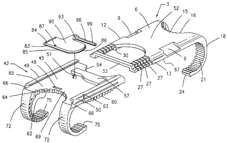
FIGURE 1 is an exploded view representative illustration of the embodiment of
Figure 1 providing detail with respect to internalized elements of the
invention.
FIGURE 2 is a view of a representative embodiment of the instant invention
illustrating body and body insert portions in ajoined or "closure" mode.
FIGURE 3 is a representative illustration of the instant invention providing a
view of the invention from a posterior perspective.
FIGURE 4 is a plan view illustration of the instant invention providing
further
detail with respect to the inventions rotary lock member in an engaged and
secured
position.
FIGURE 5 is a plan view illustration of the instant invention providing
further
detail with respect to the inventions rotary lock member in a disengaged and
position.
6
CA 02566521 2006-11-10
WO 2005/117547 PCT/US2005/018591
FIGURE 6 is a representative illustration of the instant invention providing
greater
detail of the inventions rotary lock positioning and variable length
cylindrical pegs as viewed
from a patients head viewing downwardly.
FIGURE 7 is a representative illustration of the instant invention shown as
deployed
substantially surrounding a rib pair, capturing the costal cartilage and
providing further detail
with respect to the invention's break away customizing fit capability.
FIGURE 8 is a representative anterior view illustration of the instant
invention as
deployed and substantially surrounding two rib pairs to capture position and
align portions of
a previously severed sternum.
FIGURE 9 is a side view illustration of the deployment of the invention
illustrated in
Figure 8.
FIGURE 10 is a posterior view of the instant invention as deployed and
illustrated in
Figures 8 and 9.
FIGURE 11 and 12 respectively illustrate the positioning and deployment of the
instant invention's emergency release tool (ERT).
Detailed Description of the Invention
While making and using of various embodiments of the present invention are
discussed in detail below, it should be appreciated that the present invention
provides for
inventive concepts capable of being embodied in a variety of specific
contexts. The specific
embodiments discussed herein are merely illustrative of specific manners in
which to make
and use the invention and are not to be interpreted as limiting the scope of
the instant
invention.
The claims and specification describe the invention presented and the terms
that are
7
CA 02566521 2006-11-10
WO 2005/117547 PCT/US2005/018591
employed in the claims draw their meaning from the use of such terms in the
specification.
The same terms employed in the prior art may be broader in meaning than
specifically
employed herein. Whenever there is a question between the broader definition
of such terms
used in the prior art and the more specific use of the terms herein, the more
specific meaning
is meant.
Referring now to the drawings wherein depicted elements are not necessarily
shown
to scale and wherein like or similar elements are designated by the same
reference numeral
through the several views. Figure 1 discloses an exploded view representative
illustration of
the embodiment providing detail with respect to internalized elements of the
invention.
Turning now to Figure 1.
In Figure 1 it may be observed where an embodiment of the instant invention is
comprised of impermanently joined insertion and insertion guide attachment
members (3, 42)
with each of said members having respective first (33, 69) and second (54, 15)
end portions,
first (12, 49) and second (13, 50) side portions, body portions (6, 45) having
anterior (52, 65)
and posterior (62, 67) directed surfaces. Further, each of said attachment
members (3,42)
comprise two crescent formed leg portions (18, 72) with angularly displaced
foot portions
(24, 75) and a plurality of sternum, rib and costal cartilage engagement
surfaces. The
sternum engagement surfaces of the instant invention include but are not
necessarily limited
to, non-attached end portions of each of a plurality of variable length
cylindrical pegs 60,
located on opposing side portions (49, 50) of the insertion guide 42 members
posterior
surface 62. When deployed said variable length cylindrical pegs 60 contact the
anterior
surface of each portion of severed sternum. Costal cartilage contact portions
are designated
as element 62 for insertion guide member 42, and as element 16 for insertion
member 3. It is
to be noted that the costal cartilage contact surfaces (62, 16) disclose an
irregularly contoured
8
CA 02566521 2006-11-10
WO 2005/117547 PCT/US2005/018591
surface to provide for enhanced gripping/positioning once the invention is
deployed or
"knuckled" against the costal cartilage.
Continuing with Figure 1, it is further disclosed where rotary lock member 90
is
pivotally attached to insertion guide member 42 via pivoting pin 51 insertion
through
pivoting guide aperture 93. The rotary lock 90 may additionally comprise a
sharpened,
beveled edge 83 located along the periphery of the lock's first end 85 and
second side portion
86 to assist in cutting through or otherwise displacing infringing tissue
growth.
The lock 90 of the instant invention provides for a unique capturing mechanism
having angularly displaced teeth-like structures 84 which cooperate with
reciprocating teeth-
like structures 30 positioned along the posteriorly directed surface of
insertion member 3,
first side 12 to position, secure in place and operatively combine said
insertion member 3,
said rotary lock 90, and said insertion guide member 42. Also shown in Figure
1 with respect
to rotary lock member 90 is a rapid release insertion bore 87 and resiliently
tensioned rapid
disengagement arm 96 having a positioning shoulder 99 which compressively
abuts
positioning block 57.
The instant invention provides for two emergency rapid release mechanisms to
disengage the sternum clamp. The first of said emergency release mechanisms is
disclosed
via the cooperation of a needle nose plier-like device's insertion within
lock's rapid release
insertion bore 87 and rapid release positioning divot 63. By compressing this
plier-like
apparatus once so deployed, lock 90 rotates and compresses its resiliently
tensioned spring
member 96 positionally abutting positioning block 57. Lock 90 axially rotates
upon pivoting
pin 51 which insertably traverses pivoting pin aperture 93 and precipitates
the release of the
lock's teeth-like capturing mechanism 84 from reciprocal teeth 30. Detailed
discussion and
illustration relating to the first of the invention's two emergency release
structures and
9
CA 02566521 2006-11-10
WO 2005/117547 PCT/US2005/018591
practices will be discussed in association with Figures 4 and 5.
A second emergency release mechanism allows for deployment via a complementing
emergency release tool described in association with Figures 12 and 13. The
tool is deployed
against biasing guides 9 located generally along first 12 and second 13 sides
of insertion
member 3. Detailed discussion and practices of complementing emergency release
tool and
association deployment methodology shall be discussed in association with
Figures 11 and
12. For purposes of continuing discussion with respect to Figure 1, insertion
member 3 as
illustrated in Figure 1 further comprises a plurality of biasing guides 9
located on opposite
sides of said insertion member 3 which allows leveraging insertion therein of
a
complementary prying tool to forcibly disengage insertion 3 and insertion
guide members 42
and thus facilitate rapid/emergency removal of the invention, once
positionally deployed.
Additionally shown in Figure 1 are severable insertion guide contact sections
27
which may be individually or collectively removed from the insertion member to
allow for
customized patient sizing of the clamp once deployed. A further benefit and
intended object
such dynamically customized severing of contact members 27 serves to
preemptively
extraneous contact sections 27 from areas likely to present opportunity for
invasive tissue
growth. Turning now to Figure 2.
Figure 2 illustrates a representative view of an embodiment of the instant
invention
illustrating body and body insert portions in a joined or closed mode.
In Figure 2 it is disclosed where insertion member 3 has been insertably
accommodated within guide member section 42. Most particularly, attention is
drawn to the
receiving guide channel 66 designated for this purpose and into which
severable insertion
guide contact sections 27 and insertion lip portions located on first 12 and
second sides 13 of
insertion member 3 have been positioned in the invention's closure mode. It
will be further
CA 02566521 2006-11-10
WO 2005/117547 PCT/US2005/018591
appreciated in Figure 2 where insertion bore 87 is observed positionally
overlying emergency
release channel 48 (shown in Figure 1) not illustrated Figure 2. As earlier
discussed in
association with Figure 1, the deployment of the emergency release of the
rapid sternum
closure (RSC) device of the instant invention can be effectuated utilizing a
compressing plier-
like apparatus with pointed/needle nose surfaces to cooperatively engage
channel 48, bore 87
and divot 63 to facilitate the compression of tension arm 96 and rotation of
lock 90. In
addition to elements previously discussed in association with Figure 1 and 2
it is to be noted
where element 73 discloses to a stress relief channel 73 located on the
outermost surfaces of
the invention's receiving guide channels 66. The stress relief channel 73 is
incorporated
within the outermost portion of both channels of the instant invention and as
will be
discussed in association with Figures 11 and 12 provides a means for rapid
disassociation of
the instant invention from a severed sternum when utilized in conjunction with
biasing guide
9 to pry or otherwise disassociate attachment guide member 42 from insertion
member 3.
Turning now to Figure 3.
Figure 3 is a representative illustration of the instant invention providing
posterior
perspective view of the invention.
In Figure 3 the variable length cylindrical pegs 60 of the instant invention
may be
clearly observed. Though in the illustrated embodiment of the instant
invention it is shown
where cylindrical structures are of variable, though fixed lengths, it is
easily envisioned
where compressible "pins" would serve the function to custom fit the posterior
directed
surface 62 of the clamp 42 to the anterior-most surface of each part of a
severed human
sternum. The column-like pins 60 as illustrated in Figure 3 typically form fit
against the
manubrium portion of the severed sternum with respect to the invention's
uppermost rib pair
deployment and the body section of a severed sternum with respect to the
invention's lower
11
CA 02566521 2006-11-10
WO 2005/117547 PCT/US2005/018591
portion rib pair deployment.
Also shown in Figure 3 in greater detail are foot portions 75 and 24 wherein
such
portions allow for the surrounding capture of severed sternum surfaces and
operate in
compressible communication with variable length cylindrical pins 60 to
effectuate an angular
displacement of a severed sternum, replicating the sternum's normal anatomical
configuration
to cooperatively enlist nonnal pulmonary mechanics to assist in the healing
process. Also
shown in Figure 3 are the crescent-shaped legs 18, 72 of the instant invention
which
substantially surround opposing ribs of a rib pair. The legs (18,72)
typically, though not
limitedly, embody irregularly shaped surfaces (19, 21) and are engineered to
provide
enhanced gripping contact with rib sections and facilitate positioning of the
device. Turning
now to Figures 4 and 5.
Figures 4 and 5 disclose a plan view illustration of the instant invention
providing
further detail with respect to the inventions rotary lock member in an engaged
and
disengaged mode.
Referring to Figures 4 and particularly 5 it is disclosed where deployment of
the
invention's first emergency release mechanism has been effectuated. In so
doing, lock 90
pivots upon pin 51 which disengages teeth-like structures 84 of lock 90 from
complementing
teeth-like structures 30 of insertion member 3. Further discussion with
respect to the manner
in which rotation of lock member 90 may be effectuated is consistent with that
as discussed
in association with Figures 1 through 3. Turning now to Figure 6.
FIGURE 6 is a representative illustration of the instant invention providing
greater
detail of the inventions rotary lock positioning and variable length
cylindrical pegs as viewed
from a patients head viewing downwardly.
In Figure 6 it is disclosed where insertion member 3 is to be received my
insertion
12
CA 02566521 2006-11-10
WO 2005/117547 PCT/US2005/018591
guide member 42 with insertion member 3 proceeding along line 92. Cylindrical
or similarly
intended peg-like structure 60 when viewed from the perspective in Figure 6
provide a
convex shaped dimensioning allowing the generally centermost pegs to align
with the
concave portion of the manubrium with respect to the instant invention's upper
rib pair
deployment and concave shaped portion of the manubrium in the invention's
deployment with
respect to lower rib pair/sternum deployment. Figure 6 illustrates in phantom
the receiving
channel 66 within insertion guide member 42 for receiving insertably
positioned severable
insertion guide contact member 27 and (from this illustration's perspective)
first side member
12 of insertion member 3. Figure 6 further provides additional disclosure with
respect to
crescent shaped leg portions 18 and 72 and foot portions (24, 75). Attention
in Figure 6 is
drawn to irregularly shaped surfaces 21 which typically though not limitedly
are integrated
within the concave portion of the crescent leg member to facilitate enhanced
contact service
and grasping of severed sternal halves during deployment of the invention.
Consequently
from the view provided in illustration 6 it is clear the instant invention
provides sternum
contact services via pin-like structure 60, feet portions (24, 75), irregular
surfaced contact
portions 21 which maintain contact with each half of a severed sternum along
the invention's
concave dimensioning and further maintains contact with either side of each
rib attached to
severed sternum and to which said invention has been dimensioned and
positioned to
surroundingly capture the rotary lock pivoting pin 51 is illustrated aligned
for positioning
insertion through pivoting guide aperture 93 of rotary lock 90. Further shown
in Figure 6 are
said rotary lock's 90 angularly displaced teeth-like structures 84 which
cooperate for securing
purposes with reciprocating teeth-like structures 30 integrated and positioned
along the
posterior directed surface of first side 12 of insertion member 3. Turning now
to Figure 7.
Figure 7 is a representative illustration of the instant invention providing
greater detail
13
CA 02566521 2006-11-10
WO 2005/117547 PCT/US2005/018591
of the inventions rotary lock positioning and variable length cylindrical pegs
as viewed from
a patients head viewing downwardly.
Figure 7 illustrates in additional detail the pin-like structure 60 of the
instant invention
maintaining contact with the manubrium portions of a severed sternum (82, 86).
It may be
seen in Figure 7 where the instant invention provides for complete surrounding
and
positioning of the manubrium/sternum by maintaining contact portions as noted
in
association with Figure 6. Said contact portions typically including but not
being limited to
foot portions (24, 75), leg member sections irregular surface 21 column-like
structure 60 and
costal cartilage sections (88, 89) wherein said cartilage effectively capture
the horizontally
displaced portions of clamp member (42, 3). Figures 8, 9 and 10 providing
further detail with
respect to the enhanced positioning and capturing capabilities of the instant
invention.
Turning now to Figures 8 through 10.
In Figures 8 through 10 it can be seen where a severed sternum halves are
denoted as
elements 82 and 86. The clamp of the instant invention 3 extends across both
halves of the
severed sternum 82 and 86 via crescent shaped leg portions 72 and 18
effectively capture and
surround the costal cartilage portions of each rib of a rib pair attached to
said severed
sternum. It is noted where portions 86 and 89 of the costal cartilage
effectively capture said
clamp 3 and provide a "knuckling" or otherwise form fitting structure to
further assist the
inventions secure deployment and positioning.
Figure 10 provides a posterior view of severed sternum 82 and 86 and allows
for
observation of foot portions 24 and 75 maintaining contact with said posterior
sternum
portions to effectively capture and position the sternum consistent with
positioning necessary
to effectuate normal pulmonary mechanics. Turning now to Figures 11 and 12.
Figures 11 and 12 disclose and respectively illustrate the positioning and
deployment
14
CA 02566521 2006-11-10
WO 2005/117547 PCT/US2005/018591
of the instant invention's emergency release tool (ERT).
Figure 11 illustrates the emergency/complementary release tool 100 leveraging
arms
103 and 105 are axially attached to prying portions 19, 113 for insertion into
biasing guides 9
as discussed in association with Figures 1 and incorporated within the body
structure of
insertion member 3.
In Figure 12 it seen where complimenting tool's 100 leveraging portions 103
and 105
are manipulated in a manner to expand outwardly sections 109 and 133 to create
stress along
section 73 of insertion guide member to effectuate the peeling back or
breaking away of said
guide member and thus facilitating emergency release of the clamp of the
instant invention.
Although the invention has been described with reference to specific
embodiments,
these descriptions are not meant to be construed in a limiting sense. Various
modifications of
the disclosed embodiments, as well as alternative embodiments of the invention
will become
apparent to persons skilled in the art upon reference to the description of
the invention. It
should be appreciated by those skilled in the art that the conception and the
specific
embodiment disclosed may be readily utilized as a basis for modifying or
designing other
structures for carrying out the same purposes of the present invention. It
should also be
realized by those skilled in the art that such equivalent constructions do not
depart from the
spirit and scope of the invention as set forth in the appended claims. It is
therefore,
contemplated that the claims will cover any such modifications or embodiments
that fall
within the true scope of the invention.