Note: Descriptions are shown in the official language in which they were submitted.
CA 02566691 2006-11-09
WO 2004/101071 PCT/US2004/014207
1
SPECIFICATION
TITLE
APPARATUS AND METHOD FOR DELIVERY OF THERAPEUTIC AND/OR
DIAGNOSTIC AGENTS
BACKGROUND OF THE INVENTION
The field of the present invention is devices and methods for the
delivery or placement of therapeutic or diagnostic agents into a living body.
Some medical procedures employ the infusion of therapeutic agents
into living bodies over periods of time, making a syringe inconvenient and/or
inappropriate. Such procedures have been used for the infusion of insulin, for
example. In other cases, monitoring of internal body conditions with small
sensors or other devices also makes syringes and like devices inappropriate
for
continuing access to subcutaneous tissue. To provide access in either
circumstance, ports have been devised which provide support for a flexible
cannula implanted in the body. Ports typically provide a housing which has a
mounting side that is held by tape, dressings or direct adhesive against the
body.
A flexible cannula extends from the housing into the body.
Ports used for infusion may be employed in combination with a
delivery tube extending to the housing of the port and in communication with
the
cannula as a complete infusion set. The delivery tube of such an infusion set
is in
communication with the flexible cannula through an infusion fluid chamber in
the
port to deliver therapeutic agents. Diagnostic agents such as biosensors may
be
delivered in like manner.
To place such ports or infusion sets including such ports, insertion
sets have been used. An insertion set typically includes the port and
necessarily
includes a rigid sharp such as a needle which is placed through the flexible
cannula for insertion into the body. The needle typically extends through a
resilient barrier such as a resealable resilient mass, through a chamber and
then
axially through the cannula. Once the cannula has been positioned in the body,
CA 02566691 2006-11-09
WO 2004/101071 PCT/US2004/014207
2
the port is positioned and the needle can be withdrawn. The resealing of the
mass as the needle is withdrawn prevents fluid from leaking from the port
while
remaining in position at the site. Once the port has been placed with the
flexible
cannula extending into the body, the agent or agents can be delivered.
A first type of insertion set includes an infusion set having the port
and a delivery tube in communication with the cannula. The insertion set
needle
accesses the housing through a different path than the delivery tube. The seal
is
typically bypassed by the delivery tube in this instance. Alternatively, the
insertion
set is used with a port rather than a complete infusion set. The delivery tube
is
placed after insertion of the port to complete an infusion set. The same path
is
used for the insertion needle as part of the insertion set as is used for
communicating the tube of the infusion set with the cannula. In this latter
case,
the delivery tube is associated with a hub which includes a member able to
pierce
a resealable resilient mass for communication between the delivery tube and
the
cannula once the insertion set has been disassembled through retraction of the
needle.
Mechanisms referred to as inserters have been devised to rapidly
insert the needle and cannula into the body at the site. For the infusion of
insulin
in particular, diabetics self medicate. Consequently, they, a family member or
other care provider places the port for infusion. This can be emotionally and
physically difficult when repeated infusions are required over long periods of
time.
Inserters alleviate this burden somewhat by making the placement of the needle
automatic and quick. Further, pressure by the inserter about the targeted site
reduces the sensation of pain.
Inserters typically include a housing with a driver slidable in the
housing. The driver includes a socket to receive the insertion set. A spring
is
operatively placed between the housing and the driver to advance rapidly an
insertion set positioned in the socket. A latch then controls the advancement
of
the driver. One complete system including an infusion port, an insertion set
having the infusion port and an insertion needle, and an inserter is
illustrated in
U.S. Patent No. 6,293,925.
CA 02566691 2006-11-09
WO 2004/101071 PCT/US2004/014207
3
SUMMARY OF THE INVENTION
The present invention is directed to a system for the delivery of
therapeutic and/or diagnostic agents and components thereof. The present
invention is also directed to methods of preparation and use of the system.
In a first separate aspect of the present invention, a port assembly
includes a base with a cannula extending from the mounting side and a port
opening away from the mounting side. A resilient barrier is located between
the
port and the cannula. An access hub includes a connector, a fitting and a
passage extending through the fitting and the connector. The connector is
positionable in the port at the resilient barrier. The resilient barrier is
open with the
connector positioned in the port. The connector being positionable in the port
at
the resilient barrier substantially eliminates the dead space that must be
primed
with fluid in order to achieve an accurate delivery of therapeutic agent.
In a second separate aspect of the present invention, a port
assembly includes a base with a cannula extending from the mounting side and a
port opening away from the mounting side. A valve is located between the port
and the cannula. The valve includes a resilient body with a slit therethrough.
The
slit is closed when unstressed. An access hub includes a connector, a fitting
and
a passageway extending through the fitting and the connector. The connector is
positionable at the port. The valve is open with the connector engaging the
valve
at the port. The access hub can be positioned and replaced without impacting
the
integrity of the valve. In addition, the connector need not extend through the
valve. Protrusions on either the valve or the surface of the connector can be
employed to control opening of the valve with the connector in place.
In a third separate aspect of the present invention, a port assembly
includes a base with a cannula extending from the mounting side and a port
opening away from the mounting side. A resilient barrier is located between
the
port and the cannula. An access hub includes a connector, a fitting and a
passage extending through the fitting and the connector. The resilient barrier
is in
sealing contact with the base about the cannula and in sealing contact with
the
connector about the passage. As such, flow is able to move from the passage
through the resilient barrier into the cannula with minimal priming of dead
space.
CA 02566691 2006-11-09
WO 2004/101071 PCT/US2004/014207
4
In a fourth separate aspect of the present invention, the port
assembly includes a base with a cannula extending from the mounting side at a
port opening away from the mounting side. A resilient barrier is located
between
the port and the cannula. An access hub includes a connector. A coupling
engages the port assembly and the access hub such that the access hub is
movable relative to the port assembly and the connector of the access hub is
in
communication with the cannula. The movement between the access hub and the
port assembly may be pivotal. The movement overcomes the tangling of tubes
which is a continuing problem with prior infusion sets.
In a fifth separate aspect of the present invention, the coupling
associated with the fourth separate aspect of the invention includes a
radially
resilient bearing ring and an annular surface. One of the ring and the surface
is
located on the port assembly and the other is located on the access hub. The
resilient ring may be employed with the annular surface to draw the connector
into
sealed contact with the resilient barrier.
In a sixth separate aspect of the present invention, a port assembly
includes a base with a cannula extending from the mounting side and a port
opening away from the mounting side. A resilient barrier is located between
the
port and the cannula. An access hub includes a connector positionable and
retained with the port. The access hub may include a device for assisting in
easy
separation of the access hub from the port assembly. In one embodiment, a
pivotally mounted tab includes a first position out of the way against the
base and
a second position extending outwardly from the base for easy purchase and
forced separation of the access hub from the port assembly. In a second
embodiment, the access hub includes a periphery with cut-outs having undercut
sides that allow for a manual pinching manipulation to separate the access hub
from the port assembly.
In a seventh separate aspect of the present invention, an inserter for
a port assembly includes a housing assembly and a port driver with a spring
operatively between the two. The housing assembly includes a housing having a
bore and a latch. The port driver includes a seat for receiving a port
assembly.
The port driver also includes a socket. A cannula insertion member is
positioned
in the socket and is inseparable from the socket. With the insertion member
CA 02566691 2006-11-09
WO 2004/101071 PCT/US2004/014207
inseparable from the socket, the inserter becomes disposable. Potentially, the
port assembly and an access hub could be included with the inserter as a
disposable system. The inserter can come fully prepared and sterile with seals
at
either end of the bore. The housing assembly can also serve as a package
5 serving to appropriately discard the inserter with the needle covered.
In an eighth separate aspect of the present invention, an inserter
includes a housing assembly, a port driver in the housing assembly and a
spring
operatively between the housing assembly and port driver controlled by a latch
in
the housing assembly. The inserter further includes a cannula insertion member
which is retained in a socket in one of the housing assembly and the port
driver.
A port assembly includes a base having a mounting side, a port opening away
from the mounting side and a cannula extending from the base. The cannula
insertion member is positionable at the port with the port assembly associated
with a seat in the port driver. An access hub includes a connector which is
positionable at the port with the port assembly separated from the seat.
In a ninth separate aspect of the present invention, an inserter
includes a housing assembly, a port driver in the housing assembly and a
spring
operatively between the housing assembly and port driver controlled by a latch
in
the housing assembly. The inserter further includes a cannula insertion member
which is retained in a socket in one of the housing assembly and the port
driver.
The cannula insertion member has a needle extending through the port assembly
with the port assembly at the driver and a needle hub fixed to the needle. The
needle hub is slidable in a passageway associated with the housing assembly a
distance which is limited by a stop. If the inserter is to be reusable, the
socket is
preferably split. The housing assembly includes a web from which the split
socket
depends. Levers on the other side of the web may be forced toward one another
to open the socket and release the needle hub.
In a tenth separate aspect of the present invention, a method for
preparing a port for insertion includes permanently fixing a cannula insertion
member in a socket associated with an inserter. A port assembly is positioned
in
the seat of the inserter. The inserter is cocked in preparation for placement
of the
port assembly.
CA 02566691 2006-11-09
WO 2004/101071 PCT/US2004/014207
6
In an eleventh separate aspect of the present invention, a method
for placing and connecting a port includes placing an inserter with a port
assembly, releasing the spring loaded port driver of the inserter and then
withdrawing the inserter with the cannula insertion member while leaving the
port
assembly. Further, a hub is engaged with the port assembly to open the
resilient
barrier after withdrawing the inserter.
In a twelfth separate aspect of the present invention, any of the
foregoing aspects are contemplated to be combined to further advantage.
BRIEF DESCRIPTION OF THE DRAWINGS
Figure 1 is a plan view of a port assembly.
Figure 2 is a side view of the port assembly of Figure 1.
Figure 3 is a cross-sectional view of the port assembly of Figure 1
taken through the axis thereof along line 3-3 of Figure 2.
Figure 4 is a cross-sectional view of the port assembly taken at 90
to the cross-sectional view of Figure 3.
Figure 5 is a detail view as seen in Figure 3.
Figure 6 is a perspective view of a resilient barrier.
Figure 7 is a cross-sectional view of the resilient barrier.
Figure 8 is a perspective view of a second port assembly.
Figure 9 is a cross-sectional view of the port assembly of Figure 8
taken through the axis.
Figure 10 is a cross-sectional view of a third port assembly also
taken through the axis of the assembly.
Figure 11 is a perspective view of a port inserter.
Figure 12 is a cross-sectional view of the port inserter of Figure 11
taken through the axis of the port inserter.
Figure 13 is a cross-sectional view of the port inserter of Figure 12
with the inserter discharged and closed, the view being at 90 to Figure 12.
Figure 14 is a cross-sectional view of a second port inserter taken
through the axis of the inserter.
Figure 15 is a plan view of a third port inserter.
CA 02566691 2006-11-09
WO 2004/101071 PCT/US2004/014207
7
Figure 16 is a cross-sectional view taken along an axis of the port
inserter of Figure 15.
Figure 17 is a cross-sectional view taken along an axis of the port
inserter of Figure 15 at 900 to the view of Figure 16.
Figure 18 is a cross-sectional view taken along an axis of a fourth
port inserter.
Figure 19 is a cross-sectional view taken along an axis of the port
inserter of Figure 18 at 900 to the view of Figure 18.
DETAILED DESCRIPTION OF THE PREFERRED EMBODIMENTS
Turning in detail to the drawings, Figures 1 through 7 illustrate a first
port assembly, generally designated 20. The port assembly 20 includes a base
22 which is shown to be frustoconical. The base may alternatively be
cylindrical.
Other shapes, of course, can also be employed. The base includes a mounting
side 24. The mounting side may include adhesive for retention at a site on
a{iving
body. The adhesive is preferably nondrying and may or may not include a coated
paper cover to be removed prior to use. A port 26 is arranged in the base 22
to
be open to the other side of the base from the mounting side 24. In this
embodiment, the port opens into a cavity 28 defined by a cannula mounting
element 30 and a retainer element 32 which are sonically welded, press fit or
cemented into the main part of the base 22.
A cannula 34 extends from the base 22. In this embodiment, the
cannula extends perpendicular to the mounting side 24. Other angles might be
appropriately employed. The cannula mounting element 30 provides a passage
36 into which the cannula 34 is positioned. The cannula 34 has a mounting
flange
38 to retain the cannula 34 from being drawn through the passage 36. The
cannula 34 may be retained in the cannula mounting element 30 and a seal
formed with the passage 36 through the use of adhesive, sonic welding where
the
materials are compatible, a press fit, or sealing elements. In the preferred
embodiment, the cannula mounting element 30 insures retention of the cannula
34 by ultrasonically swaging the body of the element 30 to draw material from
that
element 30 over the flange 38, as best seen in Figure 5.
CA 02566691 2006-11-09
WO 2004/101071 PCT/US2004/014207
8
The port assembly 20 further includes a resilient barrier 42. The
resilient barrier 42 is preferably an elastomer. It is positioned in the
cavity 28 and
overlies the cannula 34. The resilient barrier 42 controls fluid communication
from
the port 26 to the cannula 34.
The resilient barrier 42 is illustrated in this embodiment to be a
valve. The valve 42 is defined by a circular elastomeric septum 44. The septum
44 includes a slit 46 therethrough. The slit 46 is cut so that the valve
remains
closed when in the unstressed state. A frustoconical concavity 48 provides
relief
for flexure of the septum 44 downwardly to open the slit 46. As can best be
seen
in Figure 6, the septum 44 includes shaped protrusions 50 to influence the
distortion of the septum 44 with pressure from above. The septum 44 further
includes circular beads 52 and 54. These beads provide seals for sealing
contact
with components on either side of the septum 44. Thus, the circular bead 54
provides sealing contact with the cannula mounting element 30 about the
cannula
34 and also about the concavity 48. Thus, the resilient barrier 42 controls
communication from the port 26 to the cannula 34 through pressure on the upper
side thereof.
An access hub, generally designated 56, includes a hub 58. A
connector 60 extends from the main body of the hub 58. A tube 62 extends
laterally from the main body of the hub 58. A fitting 64 is located at the end
of the
tube 62 for receipt of an infusion tube (not shown). Other fittings may be
employed to rigidly engage such tubing or other components. A passage 66
extends through the fitting 64, the tube 62 and the connector 60 to provide
flow
communication through the access hub 56. The tube 62 has a length of reduced
outside diameter to receive a tab 68. The tab 68 is pivotally mounted about
the
area of reduced cross section of the tube 62. The tab 68 includes a split hub
70
for forced mounting on the tube 62. Ribs 72 on the tab 68 provide increased
purchase. The tab 68 has a first position as illustrated in Figures 1 and 2.
In a
second position, the tab may be pivoted to extend more aligned with the
longitudinal direction of the connector 60 for easy gripping between thumb and
forefinger.
The access hub 56 is constructed such that the connector 60 can be
positioned through the port 26 into the cavity 28 and fully against the
resilient
CA 02566691 2006-11-09
WO 2004/101071 PCT/US2004/014207
9
barrier 42, as seen in each of the relevant Figures. The bottom of the
connector
60 includes a surface able to press against the shaped protrusions 50 on the
opposed surface of the circular elastomeric septum 44. The protrusions 50
might
alternatively or additionally be found on the end of the connector 60 but it
is
preferred that they be located on the septum 44 such that rotation of the
access
hub 56 relative to the port assembly 20 will not impact on the communication
through the slit 46. The connector includes an annular surface 74 which, in
cross
section as illustrated in Figure 5, is shown to provide a segment of a circle.
The
curved portion of the surface 74 facing toward the distal end of the connector
60
aids in the location of the access hub 56 into the port assembly 20. The more
proximal portion of the annular surface 74 cooperates with a radially
resilient
bearing ring 76 located within the cavity 28. Together the annular surface 74
and
the radially resilient bearing ring 76 define a coupling between the port
assembly
and the access hub 56. The ring 76 is preferably split to create adequate
15 radial resilience. The ring 76 includes an inner concave track 78 meeting
with the
annular surface 74. The resilience in the ring 76 and the shape of the concave
track 78 cause the ring 76 to draw the connector 60 further into the cavity 28
as
the ring 76 attempts to contract. This bias forces the flat end of the
connector 60
against the circular bead 54 to result in sealing contact therebetween. The
20 placement of the connector 60 is such that the circular bead 54 is located
about
the end of the passage 66. The annular surface 74 is small enough to fit
through
the port 26 and to force open the ring 76.
The port assembly 20 and access hub 56 of this first embodiment
provide for the placement of the port assembly 20 in the body prior to an
assembly
of the port assembly 20 and the access hub 56. Once assembled, the connector
60 of the access hub 56 is biased against the septum 44, resulting in the
circular
beads 52 and 54 sealing against the connector 60 and the cannula mount element
30, respectively. The distal surface of the connector 60 forces the shaped
protrusions 50 toward the cannula 34 to open the slit 46. Once open, the slit
46
provides communication from the passage 66 to the cannula 34. Further, the
access hub 56 can be pivoted about the centerline of the connector 60. When
the
access hub 56 is removed by extraction force transmitted by the tab 68, the
slit 46
CA 02566691 2006-11-09
WO 2004/101071 PCT/US2004/014207
returns to the closed position as the force acting upon the shaped protrusion
50 is
removed.
Another port assembly, generally designated 80, is illustrated in
Figures 8 and 9. This port assembly 80 exhibits a flat rather than
frustoconical
5 profile. A base 82 again provides a mounting side 84 which may include
adhesive
86. A cannula mounting element 88 is fixed in the base 82 and has a retainer
element 90 thereabout which is also fixed in the base 82. The cannula mounting
element 88 retains a cannula 92 much as in the first embodiment. Further, a
resilient barrier 94 defined by the circular elastomeric septum 44 as
illustrated in
10 Figure 6 of the first embodiment is held between the cannula mounting
element 88
and the retainer element 90. The retainer element 90 defines a port 96. The
retainer element 90 also 'defines a post about the port 96 including an
annular
surface 98. The surface 98 defines a concave track about the post thus
defined.
An access hub generally designated 100, can be assembled with the
port assembly 80. The access hub 100 includes a hub 102 having a hub circular
periphery 104. This periphery 104 includes cut-outs 106 diametrically opposed
with undercut sides 108. The cut-outs 106 expose the base 82 so that a
pinching
of the assembly with the thumb and forefinger will separate the access hub 100
from the port assembly 80.
The hub 102 provides a cylindrical cavity 110 which has one portion
about the periphery thereof modified for the provision of a fitting 112. The
fitting
112 again provides for infusion tubing (not shown). An inclined asymmetry 114
at
the fitting 112 insures that the infusion tubing is not pushed so far into the
fitting
112 that a further passageway into the access hub 100 is closed off.
An inner hub element 116 fits within the cylindrical cavity 110 and
defines a connector 118 and a passage 120. The passage 120 extends from the
fitting 112 to through the connector 118. The passage 120 is formed as a
channel
in the inner hub element 116 and closed by the hub 102. Further, the passage
120 extends through the connector 118. As with the prior embodiment, the
connector 118 is insertable to the resilient barrier 94, operating in the same
way
as the first embodiment in the influence on opening the valve mechanism
associated therewith.
CA 02566691 2006-11-09
WO 2004/101071 PCT/US2004/014207
11
A retainer 122 is fixed to the inner web element 116. The retainer
122 is contemplated to extend fully about the inner cavity 124 defined within
the
inner hub element 116. The inner hub element 116 and the retainer 122 capture
a
radially resilient bearing ring 126 within the inner cavity 124. This bearing
ring 126
is preferably split and includes a convex annular bead 128 which cooperates
with
the annular surface 98 to define a coupling between the port assembly 80 and
the
access hub 100. Albeit the location of the elements are inverted, the ring 126
acts
in a similar way to that of the first embodiment in that it is sized and
arranged to
force the connector 118 into sealing contact with the resilient barrier 94.
Again,
one of the end surfaces of the connector 118 and the resilient barrier 94
includes
shaped protrusions to cause opening of the valve upon placement of the
connector 118 in the port 96.
A further port is illustrated in Figure 10. The access hub 130 is
identical to that of the embodiment of Figures 8 and 9. Further, Figure 8
applies
equally to the embodiments of Figure 9 and Figure 10. The port assembly 132
includes a base 134 which is defined by a cannula mounting element 136 and a
disk 138 having a cylindrical flange about the outer periphery thereof.
Together
the mounting element 136 and disk 138 provide a flow area therebetween which
is
able to reach a plurality of cannulas 142 extending from the mounting surface
144.
These cannulas 142 are rigid but are contemplated to be very short so as to
provide dispersed infusion into living tissue or multi-sensor diagnostic
access.
The cannulas are rigidly fixed within the cannula mounting element 136.
Further,
the cannula mounting element 136 provides a broader opening which
communicates with the flow area between the plate 136 and the disk 138 for
adequate distribution of infusion fluids thereabout.
Figures 11 through 19 provide inserter embodiments. These
embodiments are shown to mate with the port assembly 20. Through slight
modification of the seat within which the port assembly is positioned, the
embodiments of Figures 8 through 10 might also be accommodated. The first two
embodiments, Figures 11 through 13 and 14 are advantageously configured for
disposable use. The embodiment of Figures 15 through 17 is most
advantageously reusable. Finally, the embodiment of Figures 18 and 19 is
configured for reusable or disposable use.
CA 02566691 2006-11-09
WO 2004/101071 PCT/US2004/014207
12
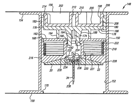
In the embodiment of Figures 11 through 13, the inserter, generally
designated 148, is shown to include a housing assembly including a housing
150.
The housing 150 is conveniently cylindrical with a bore 152 and outwardly
extending flanges 154 to define circular attachment surfaces at either end of
the
bore 152. First and second closures 156 and 158 can be retained on the flanges
154. These closures 156 and 158 include a tab 160 such that they are
conveniently removably mounted across the bore 152 with adhesive. The
closures 156 and 158 are preferably peal-off sheets commonly employed for
sterile closures.
The housing 150 further includes a mount 162 extending across the
bore 152 and integrally formed with the housing 150. The mount 162 is in the
form of a plate perpendicular to the axis of the bore 152. A central hole 164
is
provided through the mount 162 to receive a latch discussed below. Two holes
166 elongate in cross section extend to either side of the central hole 164.
These
holes are parallel and are located symmetrically about the center axis of the
housing. Certain additional holes 168 are provided through the mount 162 for
molding purposes.
The housing 150 further includes stops 170 extending inwardly in
the bore 152 and conveniently being diametrically opposed to one another. The
holes 168 for molding purposes are aligned with the stops 170 such that
molding
of the stops 170 is facilitated. Indexing tabs 172 are also diametrically
placed to
one side of the mount 162 and are also formed as part of the inner wall of the
housing 150. On the other side of the mount 162, a key 174 extends into the
bore
152 and from the mount 162.
A latch 176 is positioned to one side of the mount 162. The latch
includes a plate 178 extending substantially across the bore 152 of the
housing
150. Additionally, the latch 176 includes upwardly extending walls 180 forming
segments of a cylinder. One of these segments of the walls 180 includes a
keyway 182 which receives the key 174. The keyway 182 has a substantial
portion having a first height to receive the key 174 with the latch 176
axially
positioned as shown in Figure 12. At one point, the keyway 182 is of increased
depth parallel to the centerline of the housing 150 which allows the latch 176
to
CA 02566691 2006-11-09
WO 2004/101071 PCT/US2004/014207
13
move toward the mount 162. The walls 180 have three gaps 184 therebetween.
One of the walls 180 also includes an undercut section 186.
Hooks 188 extend in the opposite direction of the walls 180 from the
plate 178. These hooks 188 include outwardly extending barbs 190 which extend
through the central hole 164 in the mount 162. The barbs 190 have inclined
surfaces 192 such that they can be forced into the central hole 164 with the
hooks
188 exhibiting some resilience. The barbs 190 on the hooks 188 are spaced such
that once inserted through the central hole 164, they will engage the rim of
the
hole 164 regardless of the angular orientation such that the latch 176 is
permanently captured by the mount 162.
Setoffs 194 extend in the same direction from the plate 178 as the
hooks 188. These setoffs 194 are straight and parallel to one another and
equally
displaced from the axis of the housing. The setoffs 194 match the parallel
holes
166 so that the latch 176 may be forced closer to the mount 162. However, the
hooks 188 also each have an inclined surface facing outwardly which inhibits
substantial movement of the latch 176 toward the mount 162 from the position a
shown in Figure 12. In position for use, the latch 176 is oriented such that
the
standoffs 194 are not aligned with the parallel holes 166 such that the latch
176 is
held axially within the bore 152 of the housing 150. During assembly of the
inserter might the latch be angularly rotated to match the setoffs 194 with
the
parallel holes 166 to insure that assembly can be accomplished.
A cover 198 is arranged with the latch 176. The cover also includes
a plate 200 which generally lies against the plate 178 of the latch 176. A
cylindrical wall 202 extends upwardly from the plate 200. This wall 202
includes
three blocks 204 which extend radially outwardly from the wall 202. These
blocks
204 engage the gaps 184 in the upwardly extending walls 180 of the latch 176.
Consequently, rotation of the cover 198 will result in rotation of the latch
176 with
the two components in mating relationship.
The cover also includes two fingers 206 diametrically opposed and
spaced in cutout portions of the cylindrical wall 202. One of these fingers
206
includes a rounded circumferentially extending bar 208 which engages the
undercut section 186 in one of the upwardly extending wall segments 180. The
bar 208 provides some retention of the cover 198 but allows it to be removable
CA 02566691 2006-11-09
WO 2004/101071 PCT/US2004/014207
14
with a small amount of force. The two opposed fingers 206 are slightly shorter
than the full extent of the upstanding wall 202 and have inclined surfaces
207.
The fingers 206 are somewhat resilient and can move radially inwardly because
of
the cuts to either side of the fingers 206 in the cylindrical wall 202.
Centrally located in the plate 200, an integral channel 210 extends
across the cover 198. This integral channel 210 forms a chamber 212 open
toward the latch 176.
The structure of the cover 198 is such that it can be extracted from
association with the latch 176 and pulled from the housing 150. The cover 198
may then be turned over and forced into the other end of the housing 150
within
the bore 152 as seen in Figure 13. The fingers 206 resiliently ride over the
diametrically opposed stops 170 across the inclined surfaces 207 and lock on
the
upper surface of the fingers 206.
The cylindrical wall 202 has an additional rim 214 about its
circumference to fit closely within the bore 152 of the housing 150 in this
position.
As such, the lower end of the bore 152 is closed by the cover 198 after use.
The
upper end of the bore 152 remains substantially closed by the plate 178 of the
latch 176.
A port driver, generally designated 216, is slidably mounted within
the bore 152 of the housing 150. The port driver 216 includes a cylindrical
outer
wall 218 which slides within the bore 152. The cylindrical outer wall 218
includes
two gaps (not shown) diametrically opposed. These gaps mate with the indexing
tabs 172 which extend from the mount 162. These gaps also provide clearance to
allow the port driver 216 to be mounted in the housing 150 across the stops
170.
The gaps extend fully through the port driver 216 and allow for air flow as
the
driver 216 moves through the housing 150. A cylindrical inner wall 220 defines
an
annular spring cavity 221 for receiving a coil spring 222. The cylindrical
inner wall
220 includes an inwardly extending flange 224 which includes notches 226
diametrically opposed where there is no inwardly extending flange 224. As
such,
the hooks 188 which extend through the central hole 164 further extend into
the
cylindrical inner wall 220 and engage the inwardly extending flange 224 unless
aligned with the notches 226.
CA 02566691 2006-11-09
WO 2004/101071 PCT/US2004/014207
A plate 228 extends across the port driver 216 from which the
cylindrical walls 218 and 220 extend to form the annular spring cavity 221.
This
plate 228 provides a seat 230 which is shown in Figures 12 and 13 to be
conically
formed to accommodate the first embodiment port assembly 20. The seat 230
5 may easily be formed to accommodate the port assemblies 80 and 132. In this
disposable embodiment, the seat 230 does not in any way restrain the port
assembly 20 from moving away from the seat 230. The plate 228 does extend
outwardly to the wall of the bore 152 such that the stops 170 will engage the
plate
228 as it moves to the end of the housing 150.
10 The plate 228 includes a central portion 232 having holes 234
facilitating the molding process of the flanges 224. The holes are directly
aligned
with the inwardly extending flange 224 to that end. A socket 236 is centrally
located within the central portion 232. This socket 236 is sized to receive a
needle which may be forcefully fit within the socket 236 or permanently
retained
15 there by a bonding agent. In either circumstance, the socket is designed to
rigidly
and permanently fix a needle employed as a cannula insertion member.
A cannula insertion member 238 in the form of a sharp needle is
permanently affixed within the socket 236. This needle 238 extends downwardly
through the port assembly 20 and through the cannula 34 associated therewith.
The cannula 34 is fit snugly about the needle 238 such that friction does
exist
between the cannula 34 and the needle 238. The retention force thus provided
maintains the port assembly 20 in place prior to application. The adhesive on
the
mounting side 24 is formulated to have a greater separation force than the
retention force between the cannula 34 and the needle 238. Further, the base
22
is sized to miss these stops 170.
In operation, the inserter 148 is assembled by pressing the latch 176
into position with the hooks 188 extending through the central hole 164. The
cover 198 is also positioned on the latch 176 and forced into place. The latch
may
be oriented such that the parallel setoffs 194 engage the parallel holes 166
so that
the latch 176 may be forced further into the bore 152 to insure engagement
with
the port driver 216. The coil spring 222 is placed between the mount 162 and
the
port driver 216 in the annular spring cavity 221. The port driver is aligned
with the
housing 150 so that the gaps match up with the stops 170. With the spring
CA 02566691 2006-11-09
WO 2004/101071 PCT/US2004/014207
16
operatively positioned between the mount 162 and the port driver 216, the port
driver is forced upwardly and angularly displaced until the hooks 188 engage
the
inwardly extending flange 224.
The cannula insertion member 238 may originally be part of the
inserter 148 by location in the socket 236 with a bonding agent or through
forced
interference fit. Alternatively, the cannula insertion member 238 may first be
temporarily assembled with the port assembly 20 through the cannula 34 and
then
associated with the port driver 216 as the port assembly 20 is positioned.
Ultimately, the cannula insertion member 238 becomes a fixed part of the port
driver 216.
The closures 156 and 158 are then positioned and fixed on the ends
of the housing 150 and the device sterilized. Depending on the method of
sterilization, the device is sterilized after placement of the closures 156
and 158.
In use, the closures 156 and 158 are removed by pulling on the tabs
160. The inserter 148 is then placed on the body site. The cover 198 is then
rotated until the hooks 188 meet the notches 226 in the inwardly extending
flange
224, releasing the port driver 216. The spring 222 propels the port driver 216
forwardly to the end of the housing 150 where it engages the stops 170. The
port
assembly 20 is advanced with the port driver 216 until the adhesive contacts
the
surface of the body. In doing so, the cannula insertion member 238 is rapidly
advanced into the body along with the supported cannula 34. Once placed, the
housing 150 is retracted from the body retaining the port driver 216 including
the
cannula insertion member 238. The resilient barrier 42 prevents flow from the
body through the cannula 34. With the inserter 148 removed, the cover 198 is
pulled from the end of the housing 150 and placed on the other end thereof to
engage the fingers 206 with the stops 170. The container 212 defined by the
channel 210 receives the cannula insertion member 238 to cover the sharp and
close the container.
With the port assembly 20 in place and the inserter 148 removed, an
access hub 56 can then be placed. As the connector 60 is inserted into the
port
26 of the port assembly 20, the end surface of the connector 60 extends
against
the shaped protrusions 50 of the resilient barrier 42. The connector 60 does
not
extend through the slit 46 but opens the valve through its positioning in the
cavity
CA 02566691 2006-11-09
WO 2004/101071 PCT/US2004/014207
17
28. The coupling mechanism including the radially resilient bearing ring 76
and
the annular surface 74 is engaged; and the connector 60 is pressed against the
circular bead 52. The access hub 56 is then movable in the port assembly 20
and
can be pivoted to best advantage for the associated infusion tubing. Removal
of
the access hub 56, in this embodiment by the tab 68, will withdraw the
connector
60 and allow the slit 46 to again close in the resilient barrier 42.
Turning to the port driver 240 illustrated in Figure 14, the mechanism
is substantially identical to that of the embodiment of Figures 11 through 13.
However, the cover 242 is differently configured principally with a channel
244
having a container 212 which is askew to bend the cannula insertion member 246
to the side as the cover 242 is placed on the driver end of the housing 248.
Stops
250 again engage the cover 242 to hold it in place.
Turning to the inserter embodiment of Figures 15 through 17, a
reusable inserter, generally designated 252, is disclosed. The inserter
includes a
housing 254 which is substantially identical to prior housings. The bore 258
includes a mount 260 extending across the housing 254 as previously described.
However, the central hole 262 is increased in size for placement
considerations.
The port driver 264 includes a cylindrical outer wall 266 and a
cylindrical inner wall 268 defining an annular spring cavity 270. Inwardly
extending flanges 272 are located at the end of the cylindrical inner wall 268
most
adjacent the mount 260. Again, notches 274 in the inwardly extending flanges
272 are arranged diametrically. A coil spring 276 is located within the
annular
spring cavity 270. In this embodiment, the center area of the port driver 264
is
open. An annular plate 278 closes the bottom of the annular spring cavity 270
and defines a seat for a port assembly 20. In this embodiment, the base 282 of
the port assembly 20 includes a circular channel 284. The seat 280 of the
annular
plate 278 includes a retainer 286 in the form of a circular ring which engages
a
circular channel 284 with minimal release force generated by a minimal
interference fit to retain the port assembly 20 in place prior to insertion.
The cannula insertion member 288 includes a sharpened needle
290 and a needle hub 292. The needle 290 is permanently retained within the
needle hub 292. The needle hub 292 includes an engagement shoulder 294 at its
distal end and a plug 296 that fits within the port 298 of the port assembly
20.
CA 02566691 2006-11-09
WO 2004/101071 PCT/US2004/014207
18
A latch 300 is located to the other side of the mount 260 from the
port driver 264. The latch includes a plate 302 extending across the bore 258
of
the housing 254. A cylindrical wall 304 extends along the bore 258. A keyway
306 is found in the cylindrical wall 304 to receive a key 307 associated with
the
housing 254. Hooks 308 are provided as in prior embodiments but are spaced
further apart to allow for the needle hub 292.
A socket 310 is centrally located in the plate 302 of the latch 300.
This socket 310 releaseably retains the needle hub 292 which is otherwise
slidable within the socket 310. The socket 310 includes a passageway 312 which
is open at the end toward the port assembly seat 280. A shoulder 314 is
presented at the end of the passageway 312 to encounter and retain the
engagement shoulder 294 of the needle hub 292. The socket 310 is also split
diametrically along its length to form two socket elements 316. The length of
the
socket 310 is such that, in combination with the needle hub 292, the
engagement
shoulder 294 and the shoulder 314 do not stop insertion of the cannula
insertion
member until the needle 290 has penetrated the body to the point that the
associated cannula 34 will not extend beyond the needle 290. The arrangement
is designed to stop the cannula insertion member 288 before the port driver
264
has traveled fully to the stop 318 located in the bore 258 of the housing 254.
With the inserter 252 having been actuated by rotation of the latch
300 and the port assembly 20 placed, the inserter 252 can be withdrawn along
with the cannula insertion member 288 as a component of the inserter 252. Once
withdrawn, the cannula insertion member 288 can be released from the reusable
inserter 252. The plate 302 defines a slightly flexible web across the bore
258 of
the housing 254. Two opposed levers 320 extend upwardly from that web 302.
These levers are aligned with the socket elements 316 defining the socket 310.
By pinching the levers 320 together, the socket elements 316 splay apart and
release the needle hub 292. A new cannula insertion member 288 can then be
positioned in the inserter 252 by forcing it past the shoulder 314. This may
be
accomplished with or without the port assembly 20.
With the reusable inserter 252, the device may be prepared by
positioning the cannula insertion member 288 in the port assembly 20. The
cannula insertion member 288 is then engaged with the socket 310 by forcing
the
CA 02566691 2006-11-09
WO 2004/101071 PCT/US2004/014207
19
needle hub 292 through the shoulder 314 on the socket elements 316. These
levers 320 may be pinched together to facilitate this assembly. The port
assembly
20 is then forced against the port driver 264 to place the port assembly 20 in
the
seat 280 with the circular channel 284 and the circular ring 286 engaged with
slight interference. Where the port assembly has exposed adhesive on the
mounting side 322, it is advantageous that the port driver 264 is forced into
engagement with the latch 300 before placement of the port assembly 20. Once
prepared, the inserter 252 may be placed at the site and the levers 320 turned
to
rotate the latch 300 such that the hooks 308 meet the notches 274 and release
the port driver 264. The inserter 252 is then withdrawn, retaining the cannula
insertion member 288 as part of the inserter assembly. The port assembly 20
remains at the site with the cannula 34 extending into the living body. An
access
hub 56 is then positioned with the connector 60 in the port 26. Force is
applied to
engage the coupling between the two such that the access hub 56 is then
movably retained within the port assembly 20. The system is then ready for
delivery of therapeutic agents or diagnostic agents through the cannula into
the
living tissue. The access hub 56 may be withdrawn through force exerted on the
tab 68, or by pinching the access hub in the second or third embodiments. The
valve of the resilient barrier 42 responds appropriately by sealing the
pathway
when the access hub 56 is not in place and opening the pathway when it is.
A further port inserter as illustrated in Figures 18 and 19, generally
designated 324, combines a number of features of the prior port inserters. The
device may come fully sealed and sterile. Further, the port inserter 324
contemplates the intended release of the needle after use or the enclosure of
that
needle with the inserter for discard. A cylindrical housing 326, as generally
described in preceding embodiments, includes an extended length to
accommodate closure elements 328 and 330. A latch 332 operates identically to
that in the prior embodiment of Figures 15 through 17 and cooperates with a
needle hub 334 and needle 336 in a like manner. The extended portion of the
housing 326 encloses the levers of the latch 332 and receives a cover 338.
This
cover is constructed so that it may be forced against the driver 340 from the
bottom to enclose the needle 336 and lock the cover over the stops 342. The
CA 02566691 2006-11-09
WO 2004/101071 PCT/US2004/014207
driver 340 is the same as that of prior embodiments and is driven by a spring
344
in like manner. Likewise a port 20 also is as in prior embodiments.
Thus, improved ports and inserters therefor have been described.
While embodiments and applications of this invention have been shown and
5 described, it would be apparent to those skilled in the art that many more
modifications are possible without departing from the inventive concepts
herein.
The invention, therefore is not to be restricted except in the spirit of the
appended
claims.