Note: Descriptions are shown in the official language in which they were submitted.
CA 02566720 2006-11-14
WO 2005/114560 PCT/US2005/017026
POINT-OF-SALE TRANSACTION RECORDING SYSTEM
BACKGROUND OF THE INVENTION
Field of the Invention
[0001] The present invention relates generally to integrated data management
systems and
recording systems positioned at a point-of-sale ("POS") and, in particular, to
a POS transaction
recording system including a retrofit assembly for positioning a camera
security system on or
near a transaction location marker, such as a lane marker in a supermarket, or
other such standard
fixture positioned at the POS.
Description of the Related Art
[0002] There is a need in the art for a more dependable method of recording
all possible
transactions and interactions between parties. Presently, in the art, most
cameras are mounted in
ceilings, and the video is recorded in a separate location away from the POS
system. The POS
system then records the transaction information from the register to a
separate system. Finally,
the two systems are then merged together in yet another process called video
or text overlay.
[0003] Such systems are known in the art, but have several drawbacks that
result from these
current processes. First, due to positioning of the camera almost directly
above the POS, there
are often obstacles obstructing the intended line of sight. Further, this
steep angle does not
provide the optimal view of the subjects. As a result, multiple cameras are
required to ensure
that all aspects of the transaction have been recorded. In the prior art,
there are some systems
that place their cameras more effectively, but the cameras are in plain sight,
which in turn creates
two problems: 1) the customers often feel very uncomfortable; and 2) if the
customer/cashier
knows where the camera is located, they can position themselves in a way that
will prevent the
camera from viewing its intended line of sight.
[0004] Another drawback and limitation of the prior art is the integration of
the transaction
information and the video away from the POS. This remote integration process
requires the user
to run a large number of cables, often very long distances, in order to reach
the Digital Video
Recorder (DVR). Such cabling can be very expensive and it tends to lose
picture quality at long
distances. The other problem with having a remotely-positioned DVR is that
some of the people
being monitored have access to areas where the DVR is stored and POS
information is reviewed
-1-
CA 02566720 2006-11-14
WO 2005/114560 PCT/US2005/017026
(e.g. cash office and computer room). These rooms are left unsupervised far
more often than a
cash register.
SUMMARY OF THE INVENTION
[0005] It is, therefore, an object of the present invention to provide a
transaction recording
system that overcomes the deficiencies of the prior art. It is another object
of the present
invention to provide a transaction recording system that includes a video
camera effectively
positioned to view a desired scene of a transaction, such as a checkout lane
in a supermarket. It
is a further object of the present invention to provide a transaction
recording system that has an
enclosure that obscures the video camera from the consumer. It is a still
further object of the
present invention to provide a transaction recording system having an
enclosure that is capable of
being retrofitted on existing lane markers and other transaction or point-of-
sale equipment. It is
a still further object of the present invention to provide a transaction
recording system that
effects various video integration and storage processes at the point-of-sale.
[0006] Accordingly, the present invention is directed to a transaction
recording system for use
in recording a transaction occurring at a point-of-sale. The system includes a
video capture
device having a field of vision, and this device captures, produces and
transmits video data
signals representative of the field of vision of the device. Further, the
video capture device is at
least partially positioned within an enclosure located in a desired position
with respect to the
point-of-sale. The system also includes a point-of-sale processing system
located at or near the
point-of-sale, and this point-of-sale processing system: (i) receives video
data signals; (ii)
processes video data signals; (iii) stores video data signals; (iv) transmits
video data signals, or
any combination thereof. The field of vision of the video capture device views
at least a portion
of the point-of-sale during at least a portion of the transaction.
[0007] The present invention is further directed to a transaction recording
system for use in
recording a transaction occurring at a point-of-sale. The system includes
multiple video capture
devices, each having a respective field of vision and configured or adapted to
capture, produce
and transmit video data signals representative of the field of vision of the
device. Each video
capture device is at least partially positioned within an enclosure located in
a desired position
with respect to a respective point-of-sale. The system also includes multiple
video capture
systems, each in communication with a respective video capture device and
located at or near the
respective point-of-sale. Each video capture system: (i) receives video data
signals from the
-2-
CA 02566720 2006-11-14
WO 2005/114560 PCT/US2005/017026
respective video capture device; (ii) processes video data signals from the
respective video
capture device; (iii) stores video data signals from the respective video
capture device; (iv)
transmits video data signals from the respective video capture device, or any
combination
thereof. A point-of-sale central processing system is in communication with
the video capture
systems and is located at or near a point-of-sale. In addition, the central
processing system is
configured or adapted to: (i) receive video data signals from the video
capture systems; (ii)
process video data signals from the video capture, systems; (iii) store video
data signals from the
video capture systems; (iv) transmit video data signals from the video capture
systems, or any
combination thereof. The field of vision of each video capture device views at
least a portion of
the respective point-of-sale during at least a portion of the transaction.
[0008] These and other features and characteristics of the present invention,
as well as the
methods of operation and functions of the related elements of structures and
the combination of
parts and economies of manufacture, will become more apparent upon
consideration of the
following description and the appended claims with reference to the
accompanying drawings, all
of which form a part of this specification, wherein like reference numerals
designate
corresponding parts in the various figures. It is to be expressly understood,
however, that the
drawings are for the purpose of illustration and description only and are not
intended as a
definition of the limits of the invention. As used in the specification and
the claims, the singular
form of "a", "an", and "the" include plural referents unless the context
clearly dictates otherwise.
BRIEF DESCRIPTION OF THE DRAWINGS
[0009] Fig. 1 is a perspective and cutaway view of one embodiment of a
transaction recording
system according to the principles of the present invention at a point-of-
sale;
[0010] Fig. 2 is a perspective, cutaway and schematic view of the transaction
recording system
and point-of-sale of Fig. 1;
[0011] Fig. 3 is a perspective view of the transaction recording system and
point-of-sale of
Fig. 1;
[0012] Fig. 4 is a perspective and cutaway view of one embodiment of a
transaction recording
system according to the principles of the present invention;
[0013] Fig. 5 is a perspective and cutaway view of a further embodiment of a
transaction
recording system according to the principles of the present invention;
-3-
CA 02566720 2006-11-14
WO 2005/114560 PCT/US2005/017026
[0014] Fig. 6 is a perspective view of a further embodiment of a transaction
recording system
according to the principles of the present invention;
[0015] Fig. 7 is a front and rear perspective view of a further embodiment of
a transaction
recording system according to the principles of the present invention;
[0016] Fig. 8 is a perspective view of a still further embodiment of a
transaction recording
system according to the principles of the present invention;
[0017] Fig. 9 is a perspective view of a rack display according to the prior
art;
[0018] Fig. 10 is a perspective view of one embodiment of a transaction
recording system
according to the principles of the present invention used in connection with
the rack display of
Fig. 9;
100191 Fig. 11 is a set of perspective and cutaway views of another embodiment
of a
transaction recording system according to the principles of the present
invention used in
connection with the rack display of Fig. 9;
[0020] Fig. 12 is a set of perspective and cutaway views of a further
embodiment of a
transaction recording system according to the principles of the present
invention used in
connection with the rack display of Fig. 9;
[0021] Fig. 13 is a perspective and cutaway view of a further embodiment of a
transaction
recording system according to the principles of the present invention;
[0022] Fig. 14 is a front and rear perspective view of another embodiment of a
transaction
recording system according to the principles of the present invention;
[0023] Fig. 15 is a schematic view of one embodiment of a transaction
recording system
according to the principles of the present invention at multiple points-of-
sale;
[0024] Fig. 16 is a perspective and cutaway view of another embodiment of a
transaction
recording system according to the principles of the present invention at
multiple points-of-sale;
[0025] Fig. 17 is, a perspective, cutaway and schematic view of the
transaction recording
system and points-of-sale of Fig. 16.
[0026] Fig. 18 is a front view of a first embodiment of an enclosure in a
transaction recording
system according to the principles of the present invention, and in use in
connection with a lane
marker;
[0027] Fig. 19 is a rear view of the enclosure of Fig. 18;
[0028] Fig. 20 is a first side view of the enclosure of Fig. 18;
-4-
CA 02566720 2006-11-14
WO 2005/114560 PCT/US2005/017026
[0029] Fig. 21 is a second side view of the enclosure of Fig. 18;
[0030] Fig. 22 is a top view of the enclosure of Fig. 18;
[0031] Fig. 23 is a bottom view of the enclosure of Fig. 18;
[0032] Fig. 24 is a perspective view of the enclosure of Fig. 18;
[0033] Fig. 25 is a further perspective view of the enclosure of Fig. 18;
[0034] Fig. 26 is a front view of a second embodiment of an enclosure in a
transaction
recording system according to the principles of the present invention, and in
use in connection
with a lane marker;
[0035] Fig. 27 is a rear view of the enclosure of Fig. 26;
[0036] Fig. 28 is a first side view of the enclosure of Fig. 26;
[0037] Fig. 29 is a second side view of the enclosure of Fig. 26;
[0038] Fig. 30 is a top view of the enclosure of Fig. 26;
[0039] Fig. 31 is a bottom view of the enclosure of Fig. 26;
[0040] Fig. 32 is a perspective view of the enclosure of Fig. 26;
[0041] Fig. 33 is a further perspective view of the enclosure of Fig 26;
[0042] Fig. 34 is a front view of a third embodiment of an enclosure in a
transaction recording
system according to the principles of the present invention, and in use in
connection with a lane
marker;
[0043] Fig. 35 is a rear view of the enclosure of Fig. 34;
[0044] Fig. 36 is a first side view of the enclosure of Fig. 34;
[0045] Fig. 37 is a second side view of the enclosure of Fig. 34;
[0046] Fig. 38 is a top view of the enclosure of Fig. 34;
[0047] Fig. 39 is a bottom view of the enclosure of Fig. 34;
[0048] Fig. 40 is a perspective view of the enclosure of Fig. 34;
[0049] Fig. 41 is a front view of a fourth embodiment of an enclosure in a
transaction
recording system according to the principles of the present invention, and in
use in connection
with a lane marker;
[0050] Fig. 42 is a rear view of the enclosure of Fig. 41;
[0051] Fig. 43 is a first side view of the enclosure of Fig. 41;
[0052] Fig. 44 is a second side view of the enclosure of Fig. 41;
[0053] Fig. 45 is a top view of the enclosure of Fig. 41;
-5-
CA 02566720 2006-11-14
WO 2005/114560 PCT/US2005/017026
[0054] Fig. 46 is a bottom view of the enclosure of Fig. 41;
[0055] Fig. 47 is a perspective view of the enclosure of Fig. 41;
[0056] Fig. 48 is a front view of a fifth embodiment of an enclosure in a
transaction recording
system according to the principles of the present invention, and in use in
connection with a lane
marker;
[0057] Fig. 49 is a rear view of the enclosure of Fig. 48;
[0058] Fig. 50 is a first side view of the enclosure of Fig. 48;
[0059] Fig. 51 is a second side view of the enclosure of Fig. 48;
[0060] Fig. 52 is a top view of the enclosure of Fig. 48;
[0061] Fig. 53 is a bottom view of the enclosure of Fig. 48;
[0062] Fig. 54 is a perspective view of the enclosure of Fig. 48;
[0063] Fig. 55 is a further perspective view of the enclosure of Fig. 48;
[0064] Fig. 56 is a front view of a sixth embodiment of an enclosure in a
transaction recording
system according to the principles of the present invention;
[0065] Fig. 57 is a rear view of the enclosure of Fig. 56;
[0066] Fig. 58 is a first side view of the enclosure of Fig. 56;
[0067] Fig. 59 is a second side view of the enclosure of Fig. 56;
[0068] Fig. 60 is a top view of the enclosure of Fig. 56;
[0069] Fig. 61 is a bottom view of the enclosure of Fig. 56; and
[0070] Fig. 62 is a perspective view of the enclosure of Fig. 56.
DETAILED DESCRIPTION OF THE PREFERRED EMBODIMENTS
[0071] The present invention is directed to a transaction recording system 10,
as shown in
various embodiments in Figs. 1-17, and this transaction recording system 10 is
specifically
configured or adapted to be used in connection with recording a transaction
occurring at a point-
of-sale (POS) 100, as shown in various embodiments in Figs. 1-3 and 15-17. The
POS 100 can
be located at any checkout area where a customer purchases goods or services,
such as at a
supermarket, retail store, transportation terminal, etc. The transaction
recording system 10 of the
present invention is particularly useful in a supermarket setting, where the
POS 100 is a checkout
lane 102.
[0072] According to the prior art, a checkout lane 102 typically includes a
lane marker 104
having a marker enclosure 106 mounted to a pole 108. As is known in the art,
the marker
-6-
CA 02566720 2006-11-14
WO 2005/114560 PCT/US2005/017026
enclosure 106 typically houses a light 110, such that the marker enclosure 106
is illuminated and
clearly visible by the customers. Further, through the use of the light 110,
the marker enclosure
106 will indicate whether the checkout lane 102 is "open" or "closed".
[0073] Another structure that is typically located at a checkout lane 102 is a
rack display 112,
which offers various goods to the customer for perusal while he or she is
waiting in line to move
through the checkout lane 102. Further, each checkout lane 102 includes a cash
register 114, as
well as a product collection area 116, where the customer places his or her
items, a product
scanning area 118, where the employee scans the items and a product bagging
area 120, where
the scanned items collect and are placed into bags by another employee.
[0074] While a checkout lane 102, as typically embodied in a supermarket has
been discussed
above, it is envisioned that the transaction recording system 10 of the
present invention can be
used in connection with any POS 100. It is the purpose of the transaction
recording system 10 to
record various areas, persons and other objects at the POS 100 before, during
and after a
transaction has occurred.
[0075] With reference to the present invention, and as best seen in Figs. 1-3,
the transaction
recording system 10 includes a video capture device 12, and this video capture
device 12
includes a field of vision 14. Further, the video capture device 12 is capable
of capturing,
producing and/or transmitting video data signals that are representative of
the field of vision 14
of the video capture device 12. Still further, the video capture device 12 is
at least partially
positioned within an enclosure 16. The enclosure 16 is located in a desired
position with respect
to the POS 100.
[0076] The transaction recording system 10 also includes a point-of-sale (POS)
processing
system 18. The POS processing system 18 is located at or near the POS 100, and
the processing
system 18 is capable of receiving the video data signals, processing the video
data signals,
storing the video data signals and/or transmitting the video data signals. In
addition, the field of
vision 14 of the video capture device 12 views at least a portion of the POS
100 during at least a
portion of the transaction.
[0077] In the embodiment of Figs. 1-3, the video capture device 12 is mounted
or otherwise
located within the marker enclosure 106, which may act as the enclosure 16 or
in conjunction
with a separate and distinct enclosure (as shown in Figs. 18-55).
Specifically, the video capture
device 12 is a camera 20 that is positioned within the marker enclosure 106 of
the lane marker
-7-
CA 02566720 2006-11-14
WO 2005/114560 PCT/US2005/017026
104, and is therefore mounted at a high angle on a pole 108 and with respect
to the POS 100.
Such positioning maximizes the field of vision 14 and provides appropriate
visual coverage of
virtually the entire POS 100, such as the checkout lane 102. In particular,
the camera 20, and the
field of vision 14 of the camera 20, is able to view the cash register 114,
the product collection
area 116, the product scanning area 118, the product bagging area 120, as well
as the employees
(not shown), such as the cashier, bagger, etc., and the customer (not shown).
[0078] Also, in this embodiment, the POS processing system 18 includes a point-
of-sale
(POS) data converter 22, and a point-of-sale (POS) central processing unit 24.
Accordingly, in
this embodiment, and as best seen in schematic form in Fig. 2, the POS central
processing unit
24 receives the video data signals from the video capture device 12. The POS
data converter 22
is in communication with and receives data from the cash register 114. The POS
data converter
22 processes and otherwise converts this data to a usable and digital format,
and subsequeritly
transmits this data to the POS central processing unit 24.
[0079] As discussed above, the POS processing system 18, and in one embodiment
the POS
data converter 22, is capable of receiving, processing, generating and/or
transmitting point-of-
sale (POS) data from various portions of the POS 100 and converting this data
to a usable format
by the POS processing system 18, such as the POS central processing unit 24.
[0080] While Fig. 2 shows the POS data converter 22 in communication with a
cash register
114, this POS data converter 22 and/or the POS central processing unit 24 may
be in
communication with a variety of systems and subsystems in order to collect
important and
pertinent POS data before, during and after the transaction. Accordingly, the
POS processing
system 18 may collect any POS data, including, e.g.,, transaction time,
transaction date,
transaction location, transaction data, point-of-sale location, employee data,
employer data,
customer data, goods data, item data, identification data, register data,
employee/customer
interaction data, installation data, etc. Specifically, the POS processing
system 18 can collect
any amount of data that can be used in connection with the video data signal
received from the
video capture device 12 to provide a complete picture and recording of the
entire transaction, as
well as each action and interaction taking place during the transaction.
[0081] It is also envisioned that the POS processing system 18 is configured
to or otherwise
includes the appropriate software to integrate the video data signals received
from the video
capture device 12 and the POS 100 data into an integrated, overlay data
signal. For example, in
-8-
CA 02566720 2006-11-14
WO 2005/114560 PCT/US2005/017026
the above embodiment, the POS central processing unit 24 receives the video
data signals from
the video capture device 12. Further, the POS data converter 22 receives raw
data from the cash
register 114, and converts this raw data into appropriate and digitized POS
data, which is then
transmitted to the POS central processing unit 24. Finally, the POS central
processing unit 24
integrates the data signals, such as by textual overlay and other integration
techniques that are
known in the art.
[0082] In some instances, it may not be beneficial or secure to store or
otherwise save the
video data signals, the POS data, and/or the integrated data signals and
information at the POS
processing system 18, such as on the POS central processing unit 24.
Accordingly, the
integrated data signal, and/or any of the other data signals or information
can be transmitted to a
central storage and processing system 26. Accordingly, the central storage and
processing
system 26 could be positioned in a secured location away from the POS 100,
such as in the
manager's office or some other secured location or vault. Still further, the
data could be
wirelessly transmitted offsite to some other secure location.
[0083] As best seen in Fig. 3, when the enclosure 16, whether the marker
enclosure 106 itself,
or positioned within or attached to the marker enclosure 106, the video
capture device 12, such
as the camera 20, is not visually noticeable by the customer and/or employee.
Therefore, the
customer and the employee merely see the checkout lane 102 in its normal
setting with the lane
marker 104. This allows appropriate surveillance of the POS 100, including all
of the
individuals engaged in the transaction. While shown positioned on or within,
or as part of, the
lane marker 104 in Figs. 1-3, the enclosure 16 may be positioned adjacent, on,
within or
otherwise integrated with various parts and portions of the POS 100, as
discussed in detail in
connection with various embodiments hereinafter. For example, the enclosure 16
may be
positioned adjacent, on, within or integrated with the lane marker 104, a
check stand light, a
checkout lane sign, a rack display 112, a cash register 114, a dome, an
elevated enclosure 16, etc.
While not necessary, it is often desirable to place the enclosure 16, and thus
the video capture
device 12, at an elevated position with respect to at least a portion of the
POS 100.
[0084] Further, the enclosure 16 may take any shape or size, and may be
manufactured from a
variety of materials. Also, the enclosure 16 may include brackets or other
means for engaging
the video capture device 12. For example, a pair of hinged brackets may be
attached to the video
-9-
CA 02566720 2006-11-14
WO 2005/114560 PCT/US2005/017026
capture device 12, thus allowing adjustment thereof. The video capture device
12 may be
rotatable, movable, or even automatically controlled, as discussed
hereinafter.
[0085] As shown in the embodiment of Fig. 4, multiple video capture devices
12, or cameras
20, can be positioned within the marker enclosure 106, acting as the enclosure
16. In order to
obtain an unobstructed field of vision 14, the enclosure 16 must include some
surface 28 that is
at least partially transparent, or some opening 30 that allows the camera 20
to have an
appropriate field of vision 14 and collect and produce useful video data
signals. In this manner,
the video capture device 12 is capable of capturing the video data signals
when the field of vision
14 is directed through the surface 28 or opening 30.
[0086] As shown in the embodiment of Fig. 4, the cameras 20 and their
respective fields of
vision 14 are directed down through an opening 30, and in this case one or
more of the openings
30 of a grate 32. However, as opposed to a grate 32, the one or more openings
30 can be in the
form of a vent, a crack, an orifice, etc., as long as the video capture device
12 has an appropriate
field of vision 14 that allows the capture and production of video data
signals that are useful in
recording the transaction at the POS 100.
[0087] Also as seen in the embodiment of Fig. 4, the cameras 20 are positioned
adjacent the
pole 108, which extends through the marker enclosure 106 and terminates in a
fixture for the
light 110. In the embodiment of Fig. 5, only a single camera 20 is used and
the field of vision 14
of the video capture device 12 is directed through the grate 32, which
includes a plurality of
openings 30.
[0088] With reference to Fig. 6, the enclosure 16 is mounted on the pole 108,
and the marker
enclosure 106 is attached to or otherwise placed upon a portion of the
enclosure 16. In
particular, in this embodiment, the enclosure 16 is a semicircular enclosure
34. Further, a semi-
transparent surface 28, which is at least partially transparent, allows the
video capture device 12
to direct the field of vision 14 at the POS 100. It is envisioned that this
surface 28 can be clear
plastic, tinted plastic, clear glass, tinted glass, etc.
[0089] Another embodiment of the transaction recording system 10 is
illustrated in Fig. 7. In
this embodiment, multiple cameras 20 are positioned within an enclosure 16
that is attached to or
otherwise integrated with the marker enclosure 106. Specifically, the cameras
20 are placed in a
box enclosure 36, and the box enclosure 36 includes a grate 32, through which
the cameras 20
direct their respective fields of vision 14. Of course, the openings 30 and
the grate 32 are
-10-
CA 02566720 2006-11-14
WO 2005/114560 PCT/US2005/017026
illustrated as being much larger than they normally are in order to fully
illustrate the invention.
. However, in practice, the openings 30 of the grate 32 are much smaller, such
that the customer
and/or employee could not visually notice the cameras 20.
[0090] In the embodiment of Fig. 8, two semicircular enclosures 34 are
attached to the bottom
of the marker enclosure 106. Each of these semicircular enclosures 34 house a
respective camera
20, and it is envisioned that each of the cameras 20 direct their respective
fields of vision 14 at
various portions of the POS 100. While, as discussed above, the semicircular
enclosure 34 may
include a surface 28, such as a tinted glass or smoked glass, the enclosures
34 may also simply
include an opening 30 large enough to allow an unobstructed or partially
obstructed field of
vision 14 of the camera 20. Importantly, the video capture device 12 only
needs to capture and
process an appropriate amount of video data signals to identify the actions
and interactions
occurring at the POS 100.
[0091] Figs. 9-12 illustrate various embodiments that can be used in
connection with a rack
display 112. An unmodified rack display is illustrated in Fig. 9. As shown in
Fig. 10, the
semicircular enclosure 34 is placed on a surface of the rack display 112 and
operates as discussed
above. In some instances, the location of the rack display 112 makes the
surfaces of the rack
display 112 optimal for viewing various areas of the POS 100, such as
immediately in front of
the product collection area 116, product scanning area 118 and/or product
bagging area 120. In
addition, such a location on the rack display 112 allows the video capture
device 12 to monitor
customer interactions with the rack display 112.
[0092] In another embodiment, and as illustrated in Fig. 11, the video capture
device 12 can be
mounted within a portion of the rack display 112, such as a compartment 122.
Accordingly, the
compartment 122 acts as the enclosure 16 that partially obscures or hides the
video capture
device 12. In the embodiment of Fig. 11, a grate 32 is positioned on the
compartment 122, such
that the video capture device 12, or camera 20, can direct the field of vision
14 to the appropriate
area at the POS 100.
[0093] In another embodiment, and as illustrated in Fig. 12, a box enclosure
36 can be
mounted on or otherwise integrated with the rack display 112. As discussed
above, the video
capture device 12, such as the camera 20, is placed within the box enclosure
36, and the field of
vision 14 of the video capture device 12 is directed through a grate 32 to the
appropriate area of
the POS 100. It is further envisioned that the box enclosure 36 be integrated
with or otherwise
-11-
CA 02566720 2006-11-14
WO 2005/114560 PCT/US2005/017026
appropriately blend with the environment of the rack display 112, so as not to
draw attention to
the video capture device 12. For example, the box enclosure 36 could be used
for advertising or
product display.
[0094] It is further envisioned that the field of vision 14 of the video
capture device 12 can be
angled, movable, user-selectable, etc. For example, during installation, the
video capture device
12 can be appropriately adjusted and angled (such as by the above-discussed
brackets) to
maximize the field of vision 14 of the POS 100. It is also envisioned that the
POS processing
system 18 or some other processing system may be capable of controlling the
angle and other
features, characteristics and functions of the video capture device 12 from a
remote location. In
this manner, the field of vision 14, as well as other characteristics of the
video capture device 12
can be adjusted and user-selectable.
[0095] As discussed above, the enclosure 16, and thus the video capture device
12, may be
mounted on the pole 108 adjacent the POS 100. Therefore, the video capture
device 12 can be
powered, controlled, operated, etc. through one or more wires extending
through an inner area of
the pole 108. In addition, the'communication between the video capture device
12 and the POS
processing system 18 can also be through wires that extend through the pole
108.
[0096] Any number of video capture devices 12 are envisioned. For example, the
video
capture device 12 may be a camera, a video camera, a digital camera, an analog
camera, a
miniature camera, a pinhole camera, a printed circuit board-controlled camera,
a networked
camera, a closed-circuit television camera, etc.
[0097] As discussed above, the video capture device 12 may be powered from a
power supply
38. For example, as seen in Fig. 2, the power supply 38 may be hardwired and
provide power
through a wire extending through the pole 108 and to the video capture device
12. However, any
power supply capable of powering the video capture device 12 is envisioned.
For example, the
power supply 38 may be an alternating current (AC) power supply, a direct
current (DC) power
supply, an AC/DC converter, a Siamese cable, a combined video/power cable, a
solar power
supply, or any combination thereof. Further, an AC/DC converter 40 can be
placed in the
enclosure 16, such as the marker enclosure 106 to perform conversion, as is
known in the art.
[0098] As seen in Fig. 13, the cameras 20 may be powered by a solar power
supply 48. As
seen in this embodiment, it is envisioned that the marker enclosure 106 be
partially transparent,
and together with the light 110, the solar power supplies 48 are capable of
obtaining light rays
-12-
CA 02566720 2006-11-14
WO 2005/114560 PCT/US2005/017026
and converting these to energy or power in order to power the video capture
devices 12. In it
also envisioned that the solar power supplies 48 be placed on a surface
outside of the enclosure
16. The solar power supply 48 represents only one of the various options of
the powering
capabilities of the present invention.
[0099] Fig. 14 illustrates an embodiment similar to Fig. 7, however, as
opposed to using the
attached box enclosure 36 of Fig. 7, the marker enclosure 106 acts as the
enclosure 16. In
particular, the marker enclosure 106 is specifically constructed to
appropriately house the video
capture devices 12, such as the camera 20.
[00100] The video capture device 12 and the POS processing system 18, such as
the POS data
converter 22 and the POS central processing unit 24, can conununicate in a
variety of manners,
as is known in the art. For example, the communication may be hardwired,
through coaxial
cabling, through network cabling, through fiber optic cabling, in a wireless
format, over a
wireless network, etc. In addition, the field of vision 14 of the video
capture device 12 may
include a variety of portions of the POS 100, such as the checkout lane 102,
an employee, a
cashier, a bagger, a customer, a cash register 114, the product collection
area 116, the product
scanning area 118, the product bagging area 120, a product display area, such
as the rack display
112, etc.
[00101] The present invention is also directed to a transaction recording
system 10 that
includes multiple video capture devices 12, each video capture device 12
including a respective
field of vision 14. The video capture devices 12 are arranged and operated as
discussed above.
In this embodiment, each of the video capture devices 12 are in communication
with the POS
processing system 18, which again is located at or near the POS 100. The POS
processing
system 18 receives, processes, stores and/or transmits the video data signals
from each of the
video capture devices 12 as discussed above.
[00102] In one embodiment, and as illustrated in schematic form in Fig. 15,
each POS 100
includes a POS data converter 22 in communication with and configured to
receive POS data
from a respective cash register 114 or POS 100. In this embodiment, each of
the POS data
converters 22 are in communication with and transmit data to the POS central
processing unit 24,
which acts and operates as discussed above.
[00103] Also as shown in the embodiment of Fig. 15, a central storage and
processing system
26 is placed remotely from the POS 100 and includes a monitor 42, through
which the user can
-13-
CA 02566720 2006-11-14
WO 2005/114560 PCT/US2005/017026
view and otherwise interact with the integrated data sent from the POS central
processing unit 24
to the central storage and processing system 26. Still further, this
embodiment illustrates
wireless communication between the POS central processing unit 24 and the
central storage and
processing system 26. Specifically, a wireless transmitter 44 is operated by
or otherwise in
communication with the POS central processing unit 24. Further, a wireless
receiver 46 is
operated by or otherwise in communication with the central storage and
processing system 26.
The wireless transmission, receipt and processing of digital data between the
various systems and
components of the present invention occurs as is known in the art. For
example, various wireless
transmitters 44 can be used to communicate data from the video capture devices
12, cameras 20,
POS data converter 22, etc.
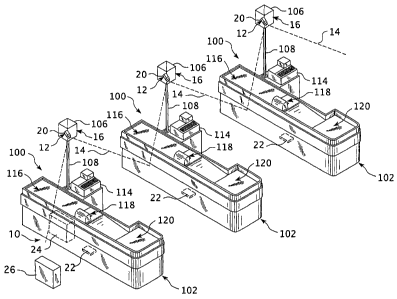
[00104] Fig. 16 illustrates this use of multiple video capture devices 12 in
connection with
multiple checkout lanes 102 in, for example, a supermarket. Again, each
checkout lane 102
includes a respective video capture device 12 and POS data converter 22. The
POS central
processing unit 24 is positioned at only a single POS 100, namely only one of
the multiple
checkout lanes 102. As seen in Fig. 17, the various video capture devices 12,
POS data
converters 22 and POS central processing unit 24 communicate and operate as
discussed above.
In addition, the POS central processing unit 24 is in communication with the
central storage
processing system 26.
[00105] As discussed above, the enclosure 16 may be formed in a variety of
shapes, sizes and
designs. Further, and also as discussed, the enclosure 16 may be designed in
various ornamental
shapes for use in connection with the lane marker 104. A first embodiment of
an ornamental
design of the enclosure 16 is illustrated in Figs. 18-25. A second embodiment
of the enclosure
16 is illustrated in Figs. 26-33. A third embodiment of the enclosure 16 is
illustrated in Figs. 34-
40. A fourth embodiment of the enclosure 16 is illustrated in Figs. 41-47.
Further, a fifth
embodiment of the enclosure 16 is illustrated in Figs. 48-55, and finally, a
sixth embodiment of
the enclosure 16 is illustrated in Figs. 56-62. In the embodiments of Figs. 18-
55, the enclosures
16 are illustrated in use in connection with a variety of styles and
structures of the lane marker
104 and marker enclosure 106. The embodiment of the enclosure in Figs. 56-62
illustrates the
enclosure 16 as mounted to the pole 108. These embodiments illustrate various
design options
for the enclosure 16.
-14-
CA 02566720 2006-11-14
WO 2005/114560 PCT/US2005/017026
[00106] In one embodiment, the video capture device 12 is a camera 20 that is
using closed-
circuit television technology. In addition, the bottom surface of the
enclosure 16 may be angled
to provide the camera 20 with the optimal field of vision 14.
[00107] In one embodiment, the light 110 may be mounted directly to the
enclosure 16. In
another embodiment, the top of the enclosure 16 is completely enclosed, such
that no light can
enter the enclosure 16 from above. The only surface where light can enter the
enclosure 16 is
through a small window or surface 28 positioned on the bottom of the camera
ericlosure 16. This
window may be concealed by a tinted plastic cover.
[00108] In this manner, the transaction recording system 10 provides many
benefits over the
prior art. For example, the transaction recording system 10 of the present
invention provides
optimal viewing angle of the intended subjects and transaction. The system 10
may include
various video capture device 12 or camera 20 locations, which will enable the
viewer to see a
much closer and less obstructed view of the transactions and interactions
occurring between the
customer and cashier.
[00109] Another advantage of the transaction recording system 10 of the
present invention is
the concealment of the video capture devices 12 or cameras 20. By concealing
the cameras 20,
the customers will not feel uncomfortable, such as they often feel when they
are being
"watched". Next, if the customer and/or the cashier knows where the camera 20
is positioned,
they can easily position themselves in a way that will prevent the camera from
viewing its
intended field of vision 14. The transaction recording system 10 of the
present invention, and
specifically the concealed camera 20, overcomes this problem.
[00110] The transaction recording system 10 greatly reduces the obstructions
in the line-of-
sight between the camera 20 and the subject. Further, the transaction
recording system 10
provides optimal camera 20 angle for viewing transactions and interactions and
reduces the total
number of cameras 20 needed to record such transactions and interactions.
Still further, the
transaction recording system 10 requires less storage space and has a longer
capture period, and
also provides higher resolution and requires fewer cables. Still further, the
transaction recording
system 10 includes video capture devices 12 that have smaller power
consumption requirements
and cost less. In addition, the POS processing system 18 of the transaction
recording system 10
allows for integration of the POS 100 data and the video signals and data at
the POS 100, which
drastically reduces the amount of necessary cabling and the chance of cable
failure. Still further,
-15-
CA 02566720 2006-11-14
WO 2005/114560 PCT/US2005/017026
the use of a secured and remote central storage and processing system 26
allows for viewing of
the integrated signal in a closely supervised location.
[00111] Although the invention has been described in detail for the purpose of
illustration
based on what is currently considered to be the most practical and preferred
embodiments, it is to
be understood that such detail is solely for that purpose and that the
invention is not limited to
the disclosed embodiments, ' but, on the contrary, is intended to cover
modifications and
equivalent arrangements that are within the spirit and scope of the appended
claims. For
example, it is to be understood that the present invention contemplates that,
to the extent
possible, one or more features of any embodiment can be combined with one or
more features of
any other embodiment.
-16-