Note: Descriptions are shown in the official language in which they were submitted.
CA 02566855 2006-11-15
WO 2005/113615 PCT/US2005/017474
TITLE: POLYMERIZATION PROCESS
INVENTORS: Robert O. Hagerty
Kevin Stavens
Marc L. DeChellis
Brett Fischbuch
James M. Farley
PRIORITY
This invention claims the benefit of provisional applications USSN
60/572,876, filed May 20, 2004, USSN 60/572,786, filed May 20, 2004 and
USSN 60/581,463, filed June 21, 2004.
FIELD OF THE INVENTION
The present invention relates to a gas phase polymerization process
operating below the Critical Temperature.
BACKGROUND OF THE INVENTION
Advances in polymerization and catalysis have resulted in the capability to
produce many new polymers having improved physical and chemical properties
useful in a wide variety of superior products and applications. With the
development of new catalysts, the choice of polymerization-type (solution,
slurry,
high pressure or gas phase) for producing a particular polymer has been
greatly
expanded. Also, advances in polymerization technology have provided more
efficient, highly productive and economically enhanced processes. Regardless
of
these technological advances in the polyolefin industry, common problems, as
well as new challenges still exist. For example, the tendency for a gas phase
process to foul and/or sheet remains a challenge, which can particularly be
dependent on the polymer being produced and the catalyst system employed.
Fouling, sheeting and/or static generation in a continuous gas phase
process, in for example heat exchangers, distributor plates, and probes, can
lead to
the ineffective operation of various reactor systems. In a typical continuous
gas
CA 02566855 2006-11-15
WO 2005/113615 PCT/US2005/017474
2
phase process, a recycle system is employed for many reasons including the
removal of heat generated in the process by the polymerization reaction, and
recycle processes offer many opportunities for fouling.
Evidence of, and solutions to, various process operability problems,
including fouling, sheeting, chunking, agglomerating and static build up, have
been addressed by many in the art. For example, U.S. Patent Nos. 4,792,592,
4,803,251, 4,855,370 and 5,391,657 all discuss techniques for reducing static
generation in a polymerization process by introducing to the process for
example,
water, alcohols, ketones, and/or inorganic chemical additives; PCT publication
WO 97/14721 published April 24, 1997 discusses the suppression of fines that
can
cause sheeting by adding an inert hydrocarbon to the reactor; U.S. Patent No.
5,066,736 and EP-Al 0 549 252 discuss the introduction of an activity retarder
to
the reactor to reduce agglomerates; EP-Al 0 453 116 discusses the introduction
of
antistatic agents to the reactor for reducing the amount of sheets and
agglomerates;
U.S. Patent No. 4,012,574 discusses the addition of a surface-active compound,
a
perfluorocarbon group, to the reactor to reduce fouling; U.S. Patent No.
5,026,795
discusses the addition of an antistatic agent with a liquid carrier to the
polymerization zone in the reactor; U.S. Patent No. 5,410,002 discusses using
a
conventional Ziegler-Natta titanium/magnesium supported catalyst system where
a selection of antistatic agents are added directly to the reactor to reduce
fouling;
U.S. Patent No. 3,470,143 describes a reduction in fouling in mostly slurry
processes for producing primarily elastomers using a fluorinated organic
carbon
compound.
Likewise, further evidence of, and solutions to, various process operability
problems have been addressed by many in the art. For example, U.S. Patent No.
3,082,198 discusses introducing an amount of a carboxylic acid dependent on
the
quantity of water in a process for polymerizing ethylene using a
titanium/aluminum organometallic catalysts in a hydrocarbon liquid medium;
U.S.
Patent No. 3,919,185 describes a slurry process using a nonpolar hydrocarbon
diluent with a conventional Ziegler-Natta-type or Phillips-type catalyst and a
CA 02566855 2006-11-15
WO 2005/113615 PCT/US2005/017474
3
polyvalent metal salt of an organic acid having a molecular weight of at least
300;
U.S. Patent No. 5,990,251 relates to increasing catalyst activity of a Ziegler-
Natta-
type catalyst by using very small quantities of a halogenated hydrocarbon,
specifically a molar ratio between 0.001 and 0.15 of the halogenated
hydrocarbon,
particularly chloroform, to the metal of the catalyst, specifically titanium;
U.S.
Patent No. 6,455,638 is directed to a polymer blend having components with
different ethylene content, and U.S. Patent No. 5,624,878 relates primarily to
the
use in polymerization of catalytic derivatives of titanium (II) and zirconium
(II)
metallocene-type complexes; both U.S. Patent Nos. 6,455,638 and 5,624,878
mention generally, in passing, using in polymerization various solvents such
as
straight-chain hydrocarbons, cyclic and alicyclic hydrocarbons, perfluorinated
hydrocarbons, aromatic and alkyl-substituted aromatic compounds, and mixtures
thereof. U.S. Patent No. 6,534,613 describes using a Ziegler-Natta-type
catalyst
in combination with a halogenated hyd'rocarbon, particularly chloroform, and
an
electron donor to produce polymers useful for making better quality films. EP
1
323 746 shows loading of biscyclopentadienyl catalyst onto a silica support in
perfluorooctane and thereafter the prepolymerization of ethylene at room
temperature. US 3,056,771 discloses polymerization of ethylene using
TiC14/(Et)3Al in a mixture of heptane and perfluoromethylcyclohexane,
presumably at room temperature.
ExxonMobil patents US 5,352,749, US 5,405,922, and US 5,436,304
disclose the use of high induced condensing agent (ICA) concentrations for
high
condensing levels, and high (heat transfer limited) production rates in gas
phase
reactors. These patents teach various means to determine the limiting
concentration of ICA (such as isopentane) that can be tolerated in the gas
phase
reactors without inducing stickiness. These patents do not note the discovery
of a
critical temperature, below which stickiness induced by high condensable
concentrations cannot occur.
Others have addresses stickiness prevention in gas phase reactors including
US patents 5,510,433, 5,342,907, 5,194,526 and 5,037,905 These patents
disclose
CA 02566855 2006-11-15
WO 2005/113615 PCT/US2005/017474
4
that very low density, sticky materials can be produced in gas phase reactors
by
adding 10-20 wt% of inert, "refractory" material to the fluid bed. Suitable
refractory materials are micro-fine silica and carbon black. However,
application of
the technology is expensive and requires substantial investment in powder
handling
equipment in the production plant.
Furthermore, It is well known that stable operation of fluidized bed reactors
used in the production of polymers requires the avoidance of conditions that
lead to
sticky polymer. Sticky, or cohesive polymer causes a range of problems in the
gas
phase reactor systems. For example, sticky polymer can reduce the quality of
fluidization that occurs within the reactor, and can reduce the degree of
internal
mixing below the minimum levels required to disperse the catalyst and maintain
stable temperature control. In addition, stickiness of the polymer can lead to
the
deposition of polymer product on the walls of the reactor expanded section,
which
often leads to the formation of dome sheets (solid masses of polymer material
deposited on the walls of the "dome", or expanded section of the reactor) In
many
cases, these dome sheets are large and massive, containing as much as 100 kg
of
agglomerated polymer. These dome sheets eventually fall from the dome and
become lodged on the distributor plate, where they interfere with
fluidization. In
some cases, the dome sheets block the product discharge port, and force a
reactor
shut-down for cleaning. For these reasons it is desirable to have means of
preventing
excessive stickiness of the polymer product.
Polymer stickiness is thought to be a function of several process and
product variables within the reactor. The relevant process variables include
the
reaction temperature and the concentrations (or partial pressures) of
condensable
components such as 1-hexene and isopentane in the reactor gas phase. In
general,
stickiness of the polymer is promoted by higher reaction temperature and
higher
condensable concentrations. Important product properties include the resin
density, molecular weight (or melt index), and the molecular weight
distribution
(MWD). In general, stickiness of the polymer is promoted by lower resin
density,
CA 02566855 2006-11-15
WO 2005/113615 PCT/US2005/017474
lower molecular weight (higher melt index), and broader molecular weight
distribution (Mw/Mn = MWD).
Fluid bed reactors used to produce polyethylene resin are normally operated
with a relatively high reaction temperature. For example, in the production of
a
5 typical low density film resin (0.917 g/cc density, 1 dg/min melt index)
produced
with metallocene or Ziegler-Natta catalyst, the reaction temperature is
typically
operated at 85 C. A relatively high reactor temperature provides for a
relatively
high temperature differential over the cooling water temperature (which
typically
operates at 30 to 35 C). This, in conventional practice, is thought to
provide for
maximum heat removal capability for maximum production rates.
It would be desirable to have a polymer production process that is free of
polymer agglomeration or stickiness. It would also be desirable to have a
process
that allows higher concentrations of condensables and/or higher dew point
temperatures in the reactors for higher production rates.
Our findings indicate that, in many cases, the operating temperatures are
too high relative to the polymer sticking temperature. Although it appears
counterintuitive, we found that it is possible to reduce operating
temperatures and
actually increase maximum production rates, while avoiding problems of resin
stickiness.
SUMMARY OF THE INVENTION
The invention is directed to a continuous process for polymerizing one or
more hydrocarbon monomer(s), preferably a gas phase process, preferably
operating in condensed mode, preferably operating with a fluidized bed, for
polymerizing one or more olefin(s) in the presence of catalyst system or
polymerization catalyst and a condensable fluid, preferably a condensable
fluid
comprising a C3 to C10 hydrocarbon, a fluorinated hydrocarbon or a combination
thereof at a temperature less than the Critical Temperature for a period of at
least
12 hours preferably 24 hours.
CA 02566855 2006-11-15
WO 2005/113615 PCT/US2005/017474
6
This invention further relates to a continuous process, preferably a gas
phase process, preferably operating in condensed mode, preferably operating
with
a fluidized bed, to polymerize one or more hydrocarbon monomers (such as
linear
or branched alpha-olefins) comprising operating the process in an insulted gas
phase reactor at a temperature less than the Critical Temperature.
This invention further relates to a continuous process, preferably a gas
phase process, preferably operating in condensed mode, preferably operating
with
a fluidized bed, to polymerize one or more hydrocarbon monomers (such as
olefins) comprising operating the process in a gas phase reactor at a bed
temperature less than the Critical Temperature and where the dew point of the
gas
in the reactor is within 20 C of the bed temperature.
This invention further relates to a continuous process, preferably a gas
phase process, preferably operating in condensed mode, preferably operating
with
a fluidized bed, to polymerize hydrocarbon monomer(s) in a reactor, said
process
comprising the steps of:
(a) introducing a recycle stream into the reactor, the recycle
stream comprising one or more monomer(s);
(b) introducing a polymerization catalyst and a condensable
fluid into the reactor where the reactor temperature is less than the Critical
Temperature for a period of more than 24 hours;
(c) withdrawing the recycle stream from the reactor;
(d) cooling the recycle stream to form a gas phase and a liquid
phase;
(e) reintroducing the gas phase and the liquid phase, separately,
and/or in combination, into the reactor;
(f) introducing into the reactor additional monomer(s) to
replace the monomer(s) polymerized; and
g) withdrawing a polymer from the reactor, preferably at a rate
of at least 50,0001b/hour (22,700 kg/hr).
CA 02566855 2006-11-15
WO 2005/113615 PCT/US2005/017474
7
Alternately, in any embodiment herein the gas phase polymerization is
operated in a condensed mode in which a liquid and a gas are introduced to a
fluidized bed reactor having a fluidizing medium, wherein the level of
condensable fluid is greater than 1 weight percent, preferably greater than 2
weight percent, more preferably greater than 10 weight percent, even more
preferably greater than 15 weight percent, still even more preferably greater
than
25 weight percent, and most preferably greater than 30 weight percent up to 60
weight percent or more, preferably 35 weiglit percent or more, based on the
total
weight of the liquid and gas entering the reactor.
In any of the above processes of the invention, a preferred catalyst system
or polymerization catalyst is a conventional-type transition metal catalyst
such as
a Ziegler-Natta-type catalyst or a Phillips-type catalyst, or a bulky ligand
metallocene-type catalyst.
BRIEF DESCRIPTION OF THE FIGURES
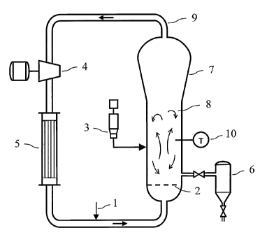
Figure 1 is a drawing of a typical gas phase process employing a recycle
stream, where catalyst (3) and monomer feed (1) enter the gas phase reactor
(7)
and are swept above the distributor plate (2) into the fluidized bed mixing
zone
(8), provided with at least one temperature monitoring probe (10) where the
monomer is polymerized into polymer that is then withdrawn via a discharge
apparatus (6), at the same time a recycle stream (9) is withdrawn from the
reactor
(7) and passed to a compressor (4), from the compressor the recycle stream is
passed to a heat exchanger (5), and thereafter the recycle stream is passed
back
into the reactor along with the monomer feed (1).
Figure 2 shows an approximation of a typical DSC melting curve of a
polymer illustrating a typical reactor temperature and the limiting resin
sticking
temperature (Ts) relative to the DSC melting curve.
CA 02566855 2006-11-15
WO 2005/113615 PCT/US2005/017474
8
DETAILED DESCRIPTION OF THE INVENTION
The invention is generally directed toward a polymerization process,
particularly a gas phase process for polymerizing one or more monomer(s) in
the
presence of a catalyst system. The invention also relates to a polymerization
process having improved operability and product capabilities. It has been
surprisingly discovered that operating at a specific set of conditions below
the
usual commercial conditions in a gas phase polymerization process (e.g. below
the
Critical Temperature) provides for a substantially improved polymerization
process and the production of polymers at commercially acceptable production
rates.
We have found that problems associated with polymer stickiness induced
by condensables in the reactor can be significantly reduced or even eliminated
by a
process involving: 1) determining the dry sticking temperature of the polymer
to be
produced, 2) determining the melting point depression of the polymer that
occurs
when a sample of the polymer to be produced is immersed in a liquid (or liquid
mixture) of the condensables to be used in the process (ICA and comonomer), 3)
operating the gas phase reactor process with a bed temperature below a
Critical
Temperature, defined as the dry sticking temperature minus melting point
depression. With the bed temperature below the Critical Temperature,
stickiness in
the resin due to high condensables concentrations is reduced or eliminated
altogether. Hence, the condensable concentrations in the reactor can then be
raised
to obtain higher dew point temperatures, higher condensing levels, and higher
production rates.
With the process of the present invention, the condensable concentration in
the reactor is not significantly limited by stickiness, so the dew point
temperature
can be raised to the allowable dew point limit, which we define as TDP (max).
In
general, the maximum allowable dew point temperature will be a function of the
bed temperature as well as the temperature of the reactor walls. (The walls of
the
reactor normally operate somewhat lower than the bed temperature.) The highest
allowable dew point temperatures are obtained with wall temperatures equal to
the
CA 02566855 2006-11-15
WO 2005/113615 PCT/US2005/017474
9
bed temperature, which is operated at or slightly below the critical
temperature.
For this reason, the use of reactors with external insulation is preferred in
some
embodiments. The external insulation may be used in combination with heating
means (electrical or steam tracing with an associated temperature control
system)
to maintain the reactor wall temperatures approximately equal to the bed
temperature (e.g. within 2 C of the bed temperature or less, preferably 1 C or
less).
To better understand the instant invention, it is useful to discuss stickiness
in gas phase reactors. Stickiness can be induced in polymers by two means: (1)
raising the temperature of the material, or (2) by increasing the
concentration of
dissolved components within the polymer. In the gas phase process, the
dissolved
components include the higher molecular weight (higher boiling) components in
the reactor gas such as, comonomers (e.g. 1-butene or 1-hexene) and induced
condensing agents (ICA's). ICA's are inert condensable fluids (typically C5 or
C6
saturated hydrocarbons) that are added to the reactor to increase the cooling
capacity of the reactor system for increased production rates. Use of ICA's is
further described in U.S. Patent Nos. 5,342,749 and 5,436,304 both of which
are
herein fully incorporated by reference. Lower molecular weight components such
as ethylene, nitrogen and hydrogen typically have only minimal solubility in
the
polymer, and therefore do not tend to induce stickiness in the polymer.
Figure 2 shows an approximation of a typical DSC melting curve of a
polymer. The melting temperature TM is taken as the peak of the melting curve.
The reactor bed temperature is normally operated considerably below the
melting
temperature as shown. For a typical LLDPE film resin (0.917 g/cc density, melt
index of 1 dg/min) the melting temperature of the polymer is in the range of
119 to
127 C (as measured dry, without dissolved components). For these grades the
bed
temperature would normally be set at 84 to 87 C. Stickiness in the polymer
would
be induced if the reactor bed temperature were increased to the point at which
it
would begin to overlap the polymer melting curve as shown in the figure. For
Ziegler-Natta catalyzed resins, stickiness occurs when approximately 15%
overlap
CA 02566855 2006-11-15
WO 2005/113615 PCT/US2005/017474
occurs (i.e. 15% of the crystalline fraction of the polymer melted). For
metallocene catalyzed resins, a higher degree of overlap is required to induce
stickiness. While the exact number is not known for metallocene, it is
believed to
be in the range of 30 to 40%.
5 Stickiness can also be induced in the polymer product by increasing the
concentration of condensables in the reactor gas phase. The condensables
become
dissolved in the polymer and act to depress the polymer melt curve. Stickiness
in
the polymer results when the melting curve is depressed to the point at which
it
overlaps the reactor operating temperature (the bed temperature).
10 Thus determination of the sticking temperature for each polymer to be
made is very useful to reactor operations. The dry sticking temperature must
be
determined in a fluid bed of the polymer to be tested operating at
substantially the
same conditions as the production process, but with no condensable gases in
the
system and with no catalyst (i.e. no reaction). The dry sticking temperature
is
determined in a reactor operating at equivalent pressure and gas velocity, but
with
the normal gas components replaced with substantially pure nitrogen. The
vessel
for the testing has a differential pressure sensor for monitoring the pressure
difference between the bottom and the top of the fluid bed (bed DP), and DP
sensors for monitoring the degree of fouling (if any) on the reactor heat
exchanger,
and distributor plate. The fluid bed is initially operated at a bed
temperature TB of
at least 40 C below the peak melting temperature Tm of the polymer to be
produced. The bed temperature is then slowly increased at a rate of 2 C per
hour.
The dry sticking temperature is taken as the temperature at which
agglomerations
or fouling on any surface of the vessel begins to occur (as evidenced by an
increase
in heat exchanger or plate DP) or the teinperature at which there is at least
a 50%
drop in bandwidth of the bed DP reading, which ever is the lesser temperature.
Once the dry sticking temperature of the system is determined then the melting
point depression of the polymer in question is determined. The melting point
depression of the polymer (ATm) is determined by first measuring the melting
temperature of a polymer by DSC, and then comparing this to a similar
CA 02566855 2006-11-15
WO 2005/113615 PCT/US2005/017474
11
measurement on a sample of the same polymer that has been soaked with the
condensable fluid or condensable fluid mixture for a period of four hours. In
general, the melting temperature of the soaked polymer will be lower than that
of
the dry polymer. The difference in these measurements is taken as the melting
point depression (ATm). Higher concentrations of dissolved materials in the
polymer cause larger depressions in the polymer melting temperature (i.e.
higher
values of ATm). A suitable DSC technique for determining the melting point
depression is described by, P.V. Hemmingsen, "Phase Equilibria in Polyethylene
Systems", Ph.D Thesis, Norwegian University of Science and Technology, March
2000. (A preferred set of conditions for conducting the tests are summarized
on
Page 112 of this reference.) The polymer melting temperature is first measured
with dry polymer, and then repeated with the polymer immersed in liquid (the
condensable fluid or condensable fluid mixture to be evaluated) where the
polymer
has been immersed for four hours. As described in the reference above, it is
important to ensure that the second part of the test, conducted in the
presence of the
liquid, is done in a sealed container so that the liquid is not flashed during
the test,
which could introduce experimental error. In conventional DSC work, it is
common to measure the "second melt" curve. This involves steps melting the
polymer in a first scan through the DSC, cooling it back to ambient
temperature,
and slowly reheating the material for the final DSC test. This second melt
method
provides improved reproducibility, but is not the preferred method for the
present
work. To determine the Critical Temperature for gas phase operation, it is
preferred to use only a single pass (or scan) in the DSC. This "first melt"
data is
believed to more accurately reflect the true melt curve of the resin as it
exists in the
reactor.
The actual depression of the polymer melting curve that will occur a gas
phase reactor will be variable depending on the concentrations of condensable
components in the system. Lower concentrations of condensables will produce
smaller depressions, and higher concentrations will produce larger
depressions. In
all cases, the actual depression will be less than or equal to the melting
point
CA 02566855 2006-11-15
WO 2005/113615 PCT/US2005/017474
12
depression measured in a liquid immersed sample. For hydrocarbons, we found
the maximum depression to typically about 19 to 22 C depending on which
hydrocarbons are used.
The Critical Temperature is defined as the dry sticking temperature minus
the melting point depression (i.e. Tc = Ts (dry) - ATm).
If the reactor bed temperature is reduced so that it is equal to or less than
the critical temperature, it is theoretically difficult, if not impossible, to
induce
stickiness in the resin by partial melting of the polymer, regardless of the
concentration of condensable components in the reactor system. It is therefore
possible to increase the ICA concentration to the point at which the dew point
temperature of the reactor gas is equal to the bed temperature. This would
produce saturation of the reactor gas with the ICA, but will not induce
stickiness
in the fluid bed.
However, with non-insulated reactor walls, it is not easy to operate with a
dew point temperature equal to the bed temperature. The walls of the reactor
(i.e.
the metal reactor vessel) normally operate at temperatures somewhat cooler
than
the fluid bed. For example, the walls of the reactor straight section are
typically 3
to 4 C lower than the bed temperature, and the walls of the expanded section
(above the fluid bed) are typically 5 to 6 C lower than the bed temperature.
In the
past, to avoid condensation on the walls of the reactor and expanded section,
it
was typical to limit the dew point temperature (and corresponding ICA
concentration) to a value approximately 10-12 C less than the bed
temperature.
Now however, we can define a maximum allowable dew point temperature as TDP
(max). It is the lowest of the following three temperatures; the reactor wall
temperature (the metal temperature in the reaction section), the reactor dome
temperature, or the reactor bed temperature. Thus, the highest allowable dew
point limits (and consequently the highest allowable production rates) will be
obtained for reactors with wall and dome temperatures approximately equal to
the
bed temperature. For this reason, the use of insulated reactors are extremely
useful in the process of the present invention. The external insulation may be
used
CA 02566855 2006-11-15
WO 2005/113615 PCT/US2005/017474
13
in combination with heating means (electrical or steam tracing with an
associated
temperature control system) to maintain the reactor wall temperatures
approximately equal to the bed temperature (e.g. within 2 C of the bed
temperature, preferably 1 C or less). In a preferred embodiment, if the
reactor
were provided with effective external insulation on both the straight section
and
the expanded section (dome), the allowable dew point temperature could be
raised
to approximately the bed temperature. This would provide a substantial
increase
in dew point temperature and corresponding increases in maximum condensed
mode production rates compared to processes of the prior art.
Suitable insulation materials include ceramic fiber, fiberglass, and calcium
silicate. The thickness of the insulation would preferably be 1 to 15 cm, and
more
preferably 5 to 8 cm. The insulation would preferably be weather-proofed to
prevent water incursion. Suitable weather-proofing material would be metal
cladding panels with sealant (or caulking) applied at the panel junctions.
Suitable instruments for measuring the reactor wall and dome temperatures
include conventional wall temperature probes. These "wall TC" probes are
typically mounted in stainless steel sheaths (3-6 mm in diameter) with a
rounded
tip that contains the thermocouple sensing element. These probes are typically
inserted through the reactor wall using an appropriate pressure sealing (or
feedthrough) device. Suitable feedthrough devices include those manufactured
by
Conax Buffalo Corp. The probes are inserted through the sealing device such
that
the tip of each probe is approximately flush with the interior wall, or extend
slightly (1-5 mm) past the wall into the reactor. Reactors are preferably
equipped
with a number of wall TC probes to monitor wall temperatures at various
positions
in the reactor section and dome.
In a preferred embodiment any of the polymerization process described
herein are a continuous process. By continuous is meant a system that operates
(or is intended to operate) without interruption or cessation. For example a
continuous process to produce a polymer would be one in which the reactants
are
CA 02566855 2006-11-15
WO 2005/113615 PCT/US2005/017474
14
continuously introduced into one or more reactors and polymer product is
continually withdrawn.
Alternately, the invention provides for a continuous gas phase process for
polymerizing one or more hydrocarbon monomer(s) in the presence of a
conventional-type transition metal catalyst or catalyst system and a
condensable
fluid, preferably a C3 to C10 hydrocarbon, a fluorinated hydrocarbon or a
mixture
thereof, wherein, the conventional-type transition metal catalyst or catalyst
system
comprises a transition metal, wherein the molar ratio of the condensable fluid
to
the transition metal is greater than 500:1, preferably the molar ratio is in
the range
of from 900:1 to 10,000:1, preferably 1500:1 to 20,000:1, and the reactor
temperature is below the Critical Temperature, optionally for more than 24
hours.
Alternately, the invention is directed to a continuous gas phase process for
polymerizing one or more hydrocarbon olefin(s), preferably at least one of
which
is ethylene or propylene, in the presence of a polymerization catalyst, in a
fluidized bed reactor, the process operating in a condensed mode in which a
liquid
and a gas are introduced to the fluidized bed reactor having a fluidizing
medium,
wlierein the level of condensable fluid, preferably a C3 to C10 hydrocarbon, a
fluorinated hydrocarbon or a mixture thereof, is greater than 1 weight
percent,
preferably greater than 2 weight percent, more preferably greater than 10
weight
percent, even more preferably greater than 15 weight percent, still even more
preferably greater than 25 weight percent, and most preferably greater than 30
weight percent up to 60 weight percent or more, preferably 35 weight percent
or
more, based on the total weight of the liquid and gas entering the reactor,
and
where the reactor temperature is below the Critical Temperature, preferably
for a
period of more than 24 hours.
In another embodiment, the polymerization catalyst comprises a metal, and
the molar ratio of the condensable fluid, to the metal is greater than 500:1,
preferably in the range of from 900:1 to 10,000:1, preferably 1500:1 to
20,000:1.
In another embodiment, the process is further operated wherein the level of
condensable liquid is greater than 1 weight percent, preferably greater than 2
CA 02566855 2006-11-15
WO 2005/113615 PCT/US2005/017474
weight percent, more preferably greater than 10 weight percent, even more
preferably greater than 15 weight percent, still even more preferably greater
than
weight percent, and most preferably greater than 30 weight percent up to 60
weight percent or more, preferably 35 weight percent or more, based on the
total
5 weight of the liquid and gas entering the reactor. In a further preferred
embodiment, the conventional-type transition metal catalyst or catalyst system
comprises a transition metal, wherein the molar ratio of the condensable
fluid,
preferably the fluorinated hydrocarbon, to the transition metal is greater
than
500:1, preferably the molar ratio is greater than 900:1, and most preferably
the
10 molar ratio is greater than 1000:1.
In an einbodiment, the invention is directed to a process, preferably a
continuous process, for polymerizing monomer(s) in a reactor, said process
comprising the steps of: (a) introducing a recycle stream into the reactor,
the
recycle stream comprising one or more monomer(s); (b) introducing a
15 polymerization catalyst or catalyst system and a condensable fluid into the
reactor
where the reactor operates at a temperature below the Critical Temperature,
preferably for a period of more than 24 hours; (c) withdrawing the recycle
stream
from the reactor; (d) cooling the recycle stream to form a gas phase and a
liquid
phase; (e) reintroducing the gas phase and the liquid phase, separately,
and/or in
20 combination, into the reactor; (f) introducing into the reactor additional
monomer(s) to replace the monomer(s) polymerized; and (g) withdrawing a
polymer product from the reactor. In a preferred embodiment, the condensable
fluid is introduced in a concentration greater than 0.5 mole percent,
preferably
greater than 1 mole percent, more preferably greater than 2 mole percent,
still
25 more preferably greater than 3 mole percent, even more preferably greater
than 4
mole percent, still even more preferably greater than 5 mole percent, still
even
more preferably greater than 7 mole percent, still even more preferably
greater
than 10 mole percent, still even more preferably greater than 15 mole percent,
still
even more preferably greater than 20 mole percent, and most preferably greater
than 25 mole percent, based on the total moles of gas in the reactor.
CA 02566855 2006-11-15
WO 2005/113615 PCT/US2005/017474
16
In any of the above processes of the invention, a preferred catalyst system
or polymerization catalyst is a conventional-type transition metal catalyst
such as
a Ziegler-Natta-type catalyst and a Phillips-type catalyst, or a bulky ligand
metallocene-type catalyst.
For purposes of this invention and the claims thereto the term "bed
temperature" is defined to mean the temperature of the fluidized bed measured
at
an elevation at least one-half of the reactor diameter above the distributor
plate
and at a radial distance at least 0.1 times the reactor diameter from the wall
of the
reactor.
Any of the embodiments described herein are preferably operated,
(preferably continuously) with a bed temperature below the Critical
Temperature
and with a dew point temperature within 25 C of the bed temperature
(preferably
within 20 C of the bed temperature, preferably within 15 C of the bed
temperature, preferably within 10 C of the bed temperature, preferably within
5
C of the bed temperature, preferably within 4 C of the bed temperature,
preferably within 3 C of the bed temperature, preferably within 2 C of the bed
temperature, preferably within 1 C of the bed temperature.
Any of the embodiments described herein are preferably continuously
operated below the Critical Temperature =for at least 12 hours, preferably at
least
24 hours, preferably at least 36 hours, preferably at least 48 hours,
preferably at
least 72 hours, preferably at least 7 days, preferably at least 14 days,
preferably at
least 21 days, preferably at least 30 days.
In any of the embodiments described herein the reactor temperature is
preferably within 10 C below the Critical Temperature, preferably within 5 C
below the Critical Temperature.
In another embodiment, this invention is directed to a continuous process
for polymerizing one or more hydrocarbon monomer(s), preferably a gas phase
process, preferably operating in condensed mode, preferably operating with a
fluidized bed, for polymerizing one or more olefin(s) in the presence of
catalyst
system or polymerization catalyst and a condensable fluid, preferably a
CA 02566855 2006-11-15
WO 2005/113615 PCT/US2005/017474
17
condensable fluid comprising a C3 to C10 hydrocarbon, a fluorinated
hydrocarbon
or a combination thereof at a temperature less than the Z Temperature (where
the
Z Temperature is the heat seal initiation temperature of the polymer to be
made
minus the melting point depression of the polymer to be made) for a period of
at
least 12 hours preferably 24 hours. Melting point depression is measured as
described above.
To determine heat seal initiation temperature, 100 kilograms of the
polymer in question are melt homogenized on a Werner Pfleiderer Model ZSK-57
twin screw extruder and pelletized. The polymer is then converted into a film
having a thickness of 1.5 to 2.0 mils (37.5 to 50 microns) using a 1 inch
Killion
Mini Cast Line, Model KLB 100. Heat seals are made from the films on a
laboratory scale Theller Model EB heat sealer. A dwell time of about one
second
and a sealing pressure of 50N/cm2 are used for making the seals. The seals on
the
films are made in the transverse direction and the heat sealing anvils are
insulated
from the heat sealing film by a Mylar film. The Mylar film is very stable at
normal heat sealing temperatures and is easily removed from the heat sealing
polymer after the seal has been made. The seals are tested within 1 minute of
sealing. For the strength test, the sealed samples are cut into 0.5 inch (1.27
cm)
wide pieces and then strength tested using an Instron instrument at a
crosshead
speed of 20 inches/min (508 mm/min) and a 2 inch (5.08 cm) jaw separation. The
free ends of the samples are fixed in the jaws, and then the jaws are
separated at
the strain rate until the seal fails. The peak load at the seal break is
measured and
the seal strength is calculated by diving the peak load by the sample width.
The
heat seal initiation temperature is determined by measuring the seal strengths
of
each sample sealed at various temperatures beginning at 50 C below the
polymer
melting point ( Tm ) and then increasing at 2 C intervals and then
extrapolating
from a plot of seal strength versus temperature to find the lowest temperature
at
which at least 0.5 N/cm seal strength is present. The heat seal initiation
temperature is the lowest temperature at which at least 0.5 N/cm seal strength
is
present.
CA 02566855 2006-11-15
WO 2005/113615 PCT/US2005/017474
18
In an alternate embodiment, in any of the embodiments described herein
the process is operated below the Z Temperature. In an alternate embodiment of
any of the embodiments described herein the process is operated below the Z
Temperature instead of below the Critical Temperature.
In another embodiment invention is directed to a continuous process for
polymerizing one or more hydrocarbon monomer(s), preferably a gas phase
process, preferably operating in condensed mode, preferably operating with a
fluidized bed, for polymerizing one or more olefin(s) in the presence of
catalyst
system or polymerization catalyst and a condensable fluid, preferably a
condensable fluid comprising a C3 to C10 hydrocarbon, a fluorinated
hydrocarbon
or a combination thereof at a temperature less than the Q Teinperature (where
the
Q Temperature is the hot tack initiation temperature of the polymer to be made
minus the melting point depression of the polymer to be made) for a period of
at
least 12 hours preferably 24 hours. Melting point depression is measured as
described above.
Hot tack strength is measured in accordance with the following procedure.
The hot tack samples are 15 mm wide specimens cut from cast films produced
according to the procedure for heat seal initiation measurement above. The
samples are back-taped (laminated) with 2 mil (approx. 50 microns)
polyethylene
terephthalate film to avoid rupture at the transition of the seal and
elongation or
sticking to the seal bars. A Hot Tack Tester 3000, from J&B (J & B Instruments
BV, Heerlen, The Netherlands or J& B instruments USA, Inc., Spartanburg, South
Carolina), was employed to make the seal, using a seal bar pressure of 0.5
MPa,
and a seal time of 0.5 sec. The hot tack force is then determined, after a
cooling
time of 0.4 seconds and at a peel speed of 200 mm/sec. The force at the seal
break
is measured and the hot tack strength is calculated by diving the hot tack
force by
the sample width. Hot tack initiation temperature is determined by measuring
the
hot tack strengths of each sample sealed at various temperatures beginning at
50
C below the polymer melting point ( Tm ) and then increasing at 2 C intervals
and then extrapolating from a plot of hot tack strength versus temperature to
find
CA 02566855 2006-11-15
WO 2005/113615 PCT/US2005/017474
19
the lowest temperature at which at least 0.06 N/cm hot tack strength is
present.
The hot tack initiation temperature is the lowest temperature where an at
least 0.06
N/cm hot tack strength is present.
In an alternate embodiment, in any of the embodiments described herein
the process is operated below the Q Temperature. In an alternate embodiment of
any of the embodiments described herein the process is operated below the Q
Temperature instead of below the Critical Temperature.
CATALYST COMPONENTS AND CATALYST SYSTEMS
All polymerization catalysts including conventional-type transition metal
catalysts are suitable for use in the polymerization process of the invention.
The
following is a non-limiting discussion of the various polymerization catalysts
useful in the process of the invention. All numbers and references to the
Periodic
Table of Elements are based on the new notation as set out in Chemical and
Engineering News, 63(5), 27 (1985). In the description herein the transition
metal
compound may be described as a catalyst precursor, a transition metal
catalyst, a
polymerization catalyst, or a catalyst compound, and these terms are used
interchangeably. The term activator is used interchangeably with the term co-
catalyst. A catalyst system is combination of a catalyst compound and an
activator.
Conventional-Type Transition Metal Catalysts
Conventional-type transition metal catalysts are those traditional Ziegler-
Natta-type catalysts and Phillips-type chromium catalysts well known in the
art.
Examples of conventional-type transition metal catalysts are discussed in U.S.
Patent Nos. 4,115,639, 4,077,904 4,482,687, 4,564,605, 4,721,763, 4,879,359
and
4,960,741, all of which are herein fully incorporated by reference. The
conventional-type transition metal catalyst compounds that may be used in the
present invention include transition metal compounds from Groups 3 to 10,
preferably 4 to 6 of the Periodic Table of Elements.
CA 02566855 2006-11-15
WO 2005/113615 PCT/US2005/017474
These conventional-type transition metal catalysts may be represented by
the formula:
MRX (I)
where M is a metal from Groups 3 to 10, preferably Group 4, more preferably
5 titanium; R is a halogen or a hydrocarbyloxy group; and x is the valence of
the
metal M, preferably x is 1, 2,3 or 4, more preferably x is 4. Non-limiting
examples of R include alkoxy, phenoxy, bromide, chloride and fluoride. Non-
limiting examples of conventional-type transition metal catalysts where M is
titanium include TiCl3, TiCl4, TiBr4, Ti(OC2H5)3C1, Ti(OC2HS)C13,
Ti(OC4H9)3C1,
10 Ti(OC3H7)2Cl2, Ti(OC2H5)2Br2, TiC13.1/3A1Cl3and Ti(OC12H25)C13.
Conventional-type transition metal catalyst compounds based on
magnesium/titanium electron-donor complexes that are useful in the invention
are
described in, for example, U.S. Patent Nos. 4,302,565 and 4,302,566, which are
herein fully incorporate by reference. The MgTiC'16 (ethyl acetate)4
derivative is
15 particularly preferred. British Patent Application 2,105,355, herein
incorporated
by reference, describes various conventional-type vanadium catalyst compounds.
Non-limiting examples of conventional-type vanadium catalyst compounds
include vanadyl trihalide, alkoxy halides and alkoxides such as VOCl31
VOCI,(OBu) where Bu is butyl and VO(OC2H5)3; vanadium tetra-halide and
20 vanadium alkoxy halides such as VC14 and VCl3(OBu); vanadium and vanadyl
acetyl acetonates and chloroacetyl acetonates such as V(AcAc)3 and VOCI2(AcAc)
where (AcAc) is an acetyl acetonate. The preferred conventional-type vanadium
catalyst compounds are VOCl31 VC14 and VOC12-OR where R is a hydrocarbon
radical, preferably a C, to C,o aliphatic or aromatic hydrocarbon radical such
as
ethyl, phenyl, isopropyl, butyl, propyl, n-butyl, iso-butyl, tertiary-butyl,
hexyl,
cyclohexyl, naphthyl, etc., and vanadium acetyl acetonates.
Conventional-type chromium catalyst compounds, often referred to as
Phillips-type catalysts, suitable for use in the present invention include
Cr031
chromocene, silyl chromate, chromyl chloride (CrO7CI2), chromium-2-ethyl-
hexanoate, chromium acetylacetonate (Cr(AcAc)3), and the like. Non-limiting
CA 02566855 2006-11-15
WO 2005/113615 PCT/US2005/017474
21
examples are disclosed in U.S. Patent Nos. 2,285,721, 3,242,099 and 3,231,550,
which are herein fully incorporated by reference.
Still other conventional-type transition metal catalyst compounds and
catalyst systems suitable for use in the present invention are disclosed in
U.S.
Patent Nos. 4,124,532, 4,302,565, 4,302,566 and 5,763,723 and published EP-A2
0 416 815 A2 and EP-Al 0 420 436, which are all herein incorporated by
reference.
The conventional-type transition metal catalysts of the invention may also
have the general formula:
M'tM"X,tYuE (II)
where M' is Mg, Mn and/or Ca; t is a number from 0.5 to 2; M" is a transition
metal such as Ti, V and/or Zr; X is a halogen, preferably Cl, Br or I; Y may
be the
same or different and is halogen, alone or in combination with oxygen, -NR2, -
OR,
-SR, -COOR, or -OSOOR, where R is a hydrocarbyl radical, in particular an
alkyl, aryl, cycloalkyl or arylalkyl radical, acetylacetonate anion in an
amount that
satisfies the valence state of M'; u is a number from 0.5 to 20; E is an
electron
donor compound selected from the following classes of compounds: (a) esters of
organic carboxylic acids; (b) alcohols; (c) ethers; (d) amines; (e) esters of
carbonic.
acid; (f) nitriles; (g) phosphoramides, (h) esters of phosphoric and
phosphorus
acid, and (j) phosphorus oxy-chloride. Non-limiting examples of complexes
satisfying the above formula include: MgTiC15-2CH3COOC2H5,
Mg3Ti2C1õ-7CH3COOC2H5, MgTiC15-6C,H5OH, MgTiC15.100CH3OH,
MgTiCl5-tetrahydrofuran, MgTi2Clõ-7C6H5CN, Mg3Ti2C112-6C6H5COOC2H5,
MgTiCl6-2CH3COOC2H5, MgTiC16-6C5H5N, MnTiC15-4C2H5OH,
MgTiCl5(OCHJ2CH3COOC2H5, MgTiC15N(C6H5)2-3CH3COOC2H5,
MgTiBr,C14-2(C,H5)2O1 Mg3V2C112-7CH3-COOC,H5, MgZrCl6-4 tetrahydrofuran.
Other catalysts may include cationic catalysts such as A1C13, and other cobalt
and
iron catalysts well known in the art.
CA 02566855 2006-11-15
WO 2005/113615 PCT/US2005/017474
22
Typically, these conventional-type transition metal catalyst compounds
(excluding some conventional-type chromium catalyst compounds) are activated
with one or more of the conventional-type cocatalysts described below.
Conventional-Type Cocatalysts
Conventional-type cocatalyst compounds for the above conventional-type
transition metal catalyst compounds may be represented by the formula:
M3M~,XZ.R3b-c (III)
wherein M3 is a metal from Group 1, 2, 12 and 13 of the Periodic Table of
Elements; M4 is a metal of Group IA of the Periodic Table of Elements; v is a
number from 0 to 1; each X2 is any halogen; c is a number from 0 to 3; each R3
is
a monovalent hydrocarbon radical or hydrogen; b is a number from 1 to 4; and
wherein b minus c is at least 1.
Other conventional-type organometallic cocatalyst compounds for the
above conventional-type transition metal catalysts have the formula:
M3R3k (IV)
where M3 is a Group 1, 2, 12 or 13 metal, such as lithium, sodium, beryllium,
barium, boron, aluminum, zinc, cadmium, and gallium; k equals 1, 2 or 3
depending upon the valency of M3 which valency in turn normally depends upon
the particular Group to which M3 belongs; and each R3 may be any monovalent
hydrocarbon radical.
Non-limiting examples of conventional-type organometallic cocatalyst
compounds of Groups 1, 2, 12 and 13 usef-ul with the conventional-type
catalyst
compounds described above include methyllithium, butyllithium, dihexylmercury,
butylmagnesium, diethylcadmium, benzylpotassium, diethylzinc, tri-n-
butylaluminum, diisobutyl ethylboron, diethylcadmium, di-n-butylzinc and tri-n-
amylboron, and, in particular, the aluminum alkyls, such as tri-hexyl-
aluminum,
triethylaluminum, trimethylaluminum, and tri-isobutylaluminum. Other
conventional-type cocatalyst compounds include mono-organohalides and
hydrides of Group 2 metals, and mono- or di-organohalides and hydrides of
Group
CA 02566855 2006-11-15
WO 2005/113615 PCT/US2005/017474
23
13 metals. Non-limiting examples of such conventional-type cocatalyst
compounds include di-isobutylaluminum bromide, isobutylboron dichloride,
methyl magnesium chloride, ethylberyllium chloride, ethylcalcium bromide, di-
isobutylaluminum hydride, methylcadmium hydride, diethylboron hydride,
hexylberyllium hydride, dipropylboron hydride, octylmagnesium hydride,
butylzinc hydride, dichloroboron hydride, di-bromo-aluminum hydride and
bromocadmium hydride. Conventional-type organometallic cocatalyst
compounds are known to those in the art, and a more complete discussion of
these
compounds may be found in U.S. Patent Nos. 3,221,002 and 5,093,415, which are
herein fully incorporated by reference.
For purposes of this patent specification and appended claims
conventional-type transition metal catalyst compounds exclude those bulky
ligand
metallocene-type catalyst compounds discussed below. For purposes of this
patent specification and the appended claims the term "cocatalyst" refers to
conventional-type cocatalysts or conventional-type organometallic cocatalyst
compounds.
In some embodiment, however, it is preferred that the catalyst system not
comprise titanium tetrachloride, particularly not the combination of TiC14 and
aluminum alkyl (such as triethylaluminum), particularly when the FC is a
perfluorocarbon. In situations where the catalyst is titanium tetrachloride,
particularly the combination of TiCl4 and aluminum alkyl (such as
triethylaluminum) the FC is preferably a hydrofluorocarbon. In another
embodiment, the catalyst is not a free radical initiator, such as a peroxide.
Bulky Ligand Metallocene-Type Catalyst Compounds
Generally, polymerization catalysts useful in the invention include one or
more bulky ligand metallocene compounds (also referred to herein as
metallocenes). Typical bulky ligand metallocene compounds are generally
described as containing one or more bulky ligand(s) and one or more leaving
group(s) bonded to at least one metal atom. The bulky ligands are generally
CA 02566855 2006-11-15
WO 2005/113615 PCT/US2005/017474
24
represented by one or more open, acyclic, or fused ring(s) or ring system(s)
or a
combination thereof. These bulky ligands, preferably the ring(s) or ring
system(s)
are typically composed of atoms selected from Groups 13 to 16 atoms of the
Periodic Table of Elements; preferably the atoms are selected from the group
consisting of carbon, nitrogen, oxygen, silicon, sulfur, phosphorous,
germanium,
boron and aluminum or a combination thereof. Most preferably, the ring(s) or
ring system(s) are composed of carbon atoms such as, but not limited to, those
cyclopentadienyl ligands or cyclopentadienyl-type ligand structures or other
similar functioning ligand structure such as a pentadiene, a
cyclooctatetraendiyl or
an imide ligand. The metal atom is preferably selected from Groups 3 through
15
and the lanthanide or actinide series of the Periodic Table of Elements.
Preferably
the metal is a transition metal from Groups 4 through 12, more preferably
Groups
4, 5 and 6, and most preferably the transition metal is from Group 4.
Exemplary of these bulky ligand metallocene-type catalyst compounds and
catalyst systems are described in for example, U.S. Patent Nos. 4,530,914,
4,871,705, 4,937,299, 5,017,714, 5,055,438, 5,096, 867, 5,120,867, 5,124,418,
5,198,401, 5,210,352, 5,229,478, 5,264,405, 5,278,264, 5,278,119, 5,304,614,
5,324,800, 5,347,025, 5,350,723, 5,384,299, 5,391,790, 5,391,789, 5,399,636,
5,408,017, 5,491,207, 5,455,366, 5,534,473, 5,539,124, 5,554,775, 5,621,126,
5,684,098, 5,693,730, 5,698,634, 5,710,297, 5,712,354, 5,714,427, 5,714,555,
5,728,641, 5,728,839, 5,753,577, 5,767,209, 5,770,753 and 5,770,664 all of
which
are herein fully incorporated by reference. Also, the disclosures of European
publications EP-A-0 591 756, EP-A-0 520 732, EP-A- 0 420 436, EP-B1 0 485
822, EP-B 1 0 485 823, EP-A2-0 743 324 and EP-B 1 0 518 092 and PCT
publications WO 91/04257, WO 92/00333, WO 93/08221, WO 93/08199, WO
94/01471, WO 96/20233, WO 97/15582, WO 97/19959, WO 97/46567, WO
98/01455, WO 98/06759 and WO 98/011144 are all herein fully incorporated by
reference for purposes of describing typical bulky ligand metallocene-type
catalyst
compounds and catalyst systems.
CA 02566855 2006-11-15
WO 2005/113615 PCT/US2005/017474
In one embodiment, the polymerization catalyst useful in the process of the
invention includes one or more bulky ligand metallocene catalyst compounds
represented by the formula:
LALBMQ. (V)
5 where M is a metal atom from the Periodic Table of the Elements and may be a
Group 3 to 12 metal or from the lanthanide or actinide series of the Periodic
Table
of Elements, preferably M is a Group 4, 5 or 6 transition metal, more
preferably M
is a Group 4 transition metal, even more preferably M is zirconium, hafnium or
titanium. The bulky ligands, LA and LB, are open, acyclic or fused ring(s) or
ring
10 system(s) and are any ancillary ligand system, including unsubstituted or
substituted, cyclopentadienyl ligands or cyclopentadienyl-type ligands,
heteroatom substituted and/or heteroatom containing cyclopentadienyl-type
ligands. Non-limiting examples of bulky ligands include cyclopentadienyl
ligands, cyclopentaphenanthreneyl ligands, indenyl ligands, benzindenyl
ligands,
15 fluorenyl ligands, octahydrofluorenyl ligands, cyclooctatetraendiyl
ligands,
cyclopentacyclododecene ligands, azenyl ligands, azulene ligands, pentalene
ligands, phosphoyl ligands, phosphinimine (WO 99/40125), pyrrolyl ligands,
pyrozolyl ligands, carbazolyl ligands, borabenzene ligands and the like,
including
hydrogenated versions thereof, for example tetrahydroindenyl ligands. In one
20 embodiment, L" and LB may be any other ligand structure capable of 7r-
bonding to
M. In yet another embodiment, the atomic molecular weight (MW) of L" or LB
exceeds 60 a.m.u., preferably greater than 65 a.m.u. In another embodiment, L
A
and LB may comprise one or more heteroatoms, for example, nitrogen, silicon,
boron, germanium, sulfur and phosphorous, in combination with carbon atoms to
25 form an open, acyclic, or preferably a fused, ring or ring system, for
example, a
hetero-cyclopentadienyl ancillary ligand. Other LA and LB bulky ligands
include
but are not limited to bulky amides, phosphides, alkoxides, aryloxides,
imides,
carbolides, borollides, porphyrins, phthalocyanines, corrins and other
polyazomacrocycles. Independently, each L" and LB may be the same or different
CA 02566855 2006-11-15
WO 2005/113615 PCT/US2005/017474
26
type of bulky ligand that is bonded to M. In one embodiment of Formula V only
one of either LA or LB is present.
Independently, each L" and LB may be unsubstituted or substituted with a
combination of substituent groups R. Non-limiting examples of substituent
groups R include one or more from the group selected from hydrogen, or linear,
branched alkyl radicals, or alkenyl radicals, alkynyl radicals, cycloalkyl
radicals or
aryl radicals, acyl radicals, aroyl radicals, alkoxy radicals, aryloxy
radicals,
alkylthio radicals, dialkylamino radicals, alkoxycarbonyl radicals,
aryloxycarbonyl radicals, carbomoyl radicals, alkyl- or dialkyl- carbamoyl
radicals, acyloxy radicals, acylamino radicals, aroylamino radicals, straight,
branched or cyclic, alkylene radicals, or combination thereof. In a preferred
embodiment, substituent groups R have up to 50 non-hydrogen atoms, preferably
from 1 to 30 carbon, that can also be substituted with halogens or heteroatoms
or
the like. Non-limiting examples of alkyl substituents R include methyl, ethyl,
propyl, butyl, pentyl, hexyl, cyclopentyl, cyclohexyl, benzyl or phenyl groups
and
the like, including all their isomers, for example tertiary butyl, isopropyl,
and the
like. Other hydrocarbyl radicals include fluoromethyl, fluoroethyl,
difluoroethyl,
iodopropyl, bromohexyl, chlorobenzyl and hydrocarbyl substituted
organometalloid radicals including trimethylsilyl, trimethylgermyl,
methyldiethylsilyl and the like; and halocarbyl-substituted organometalloid
radicals including tris(trifluoromethyl)-silyl, methyl-
bis(difluoromethyl)silyl,
bromomethyldimethylgermyl and the like; and disubstitiuted boron radicals
including dimethylboron for example; and disubstituted pnictogen radicals
including dimethylamine, dimethylphosphine, diphenylamine,
methylphenylphosphine, chalcogen radicals including methoxy, ethoxy, propoxy,
phenoxy, methylsulfide and ethylsulfide. Non-hydrogen substituents R include
the atoms carbon, silicon, boron, aluminum, nitrogen, phosphorous, oxygen,
tin,
sulfur, germanium and the like, including olefins such as but not limited to
olefinically unsaturated substituents including vinyl-terminated ligands, for
example but-3-enyl, prop-2-enyl, hex-5-enyl and the like. Also, at least two R
CA 02566855 2006-11-15
WO 2005/113615 PCT/US2005/017474
27
groups, preferably two adjacent R groups, are joined to form a ring structure
having from 3 to 30 atoms selected from carbon, nitrogen, oxygen, phosphorous,
silicon, germanium, aluminum, boron or a combination thereof. Also, a
substituent group R group such as 1-butanyl may form a carbon sigma bond to
the
metal M.
Other ligands may be bonded to the metal M, such as at least one leaving
group Q. In one embodiment, Q is a monoanionic labile ligand having a sigma-
bond to M. Depending on the oxidation state of the metal, the value for n is
0, 1
or 2 such that Formula V above represents a neutral bulky ligand metallocene
catalyst compound.
Non-limiting examples of Q ligands include weak bases such as amines,
phosphines, ethers, carboxylates, dienes, hydrocarbyl radicals having from 1
to 20
carbon atoms, hydrides or halogens and the like or a combination thereof. In
another embodiment, two or more Q's form a part of a fused ring or ring
system.
Other examples of Q ligands include those substituents for R as described
above
and including cyclobutyl, cyclohexyl, heptyl, tolyl, trifluromethyl,
tetramethylene,
pentametlrylene, methylidene, methyoxy, ethyoxy, propoxy, phenoxy, bis(N-
methylanilide), dimethylamide, dimethylphosphide radicals and the like.
In another embodiment, the polymerization catalysts useful in the process
of the invention may include one or more bulky ligand metallocene catalyst
compounds where L" and LB of Formula V are bridged to each other by at least
one bridging group, A, as represented by:
L"ALBMQn (Vl)
wherein LA, LB, M, Q and n are as defined above. These compounds of Formula
VI are known as bridged, bulky ligand metallocene catalyst compounds. Non-
limiting examples of bridging group A include bridging groups containing at
least
one Group 13 to 16 atom, often referred to as a divalent moiety such as but
not
limited to at least one of a carbon, oxygen, nitrogen, silicon, aluminum,
boron,
germanium and tin atom or a combination thereof. Preferably bridging group A
contains a carbon, silicon or germanium atom, most preferably A contains at
least
CA 02566855 2006-11-15
WO 2005/113615 PCT/US2005/017474
28
one silicon atom or at least one carbon atom. The bridging group A may also
contain substituent groups R as defined above including halogens and iron. Non-
limiting examples of bridging group A may be represented by R'2C, R'2Si, R'2Si
R'2Si, R'2Ge, R'P, where R' is independently, a radical group which is
hydride,
hydrocarbyl, substituted hydrocarbyl, halocarbyl, substituted halocarbyl,
hydrocarbyl-substituted organometalloid, halocarbyl-substituted
organometalloid,
disubstituted boron, disubstituted pnictogen, substituted chalcogen, or
halogen or
two or more R' may be joined to form a ring or ring system. In one embodiment,
the bridged, bulky ligand metallocene catalyst compounds of Formula VI have
two or more bridging groups A(EP-B1-0 664 301, which is incorporated herein
by reference).
In another embodiment, the bulky ligand metallocene catalyst compounds
are those where the R substituents on the bulky ligands LA and LB of Formulas
V
and VI are substituted with the same or different number of substituents on
each of
the bulky ligands. In another embodiment, the bulky ligands LA and LB of
Formulas V and VI are different from each other.
Other bulky ligand metallocene catalyst compounds and catalyst systems
useful in the invention may include those described in U.S. Patent Nos.
5,064,802,
5,145,819, 5,149,819, 5,243,001, 5,239,022, 5,276,208, 5,296,434, 5,321,106,
5,329,031, 5,304,614, 5,677,401, 5,723,398, 5,753,578, 5,854,363, 5,856,547
5,858,903, 5,859,158, 5,900,517 and 5,939,503 and PCT publications WO
93/08221, WO 93/08199, WO 95/07140, WO 98/11144, WO 98/41530, WO
98/41529, WO 98/46650, WO 99/02540 and WO 99/14221 and European
publications EP-A-0 578 838, EP-A-0 638 595, EP-B-0 513 380, EP-A1-0 816
372, EP-A2-0 839 834, EP-B1-0 632 819, EP-B1-0 748 821 and EP-B1-0 757
996, all of which are herein fully incorporated by reference.
In another embodiment, the catalyst compositions of the invention may
include bridged heteroatom, mono-bulky ligand metallocene compounds. These
types of catalysts and catalyst systems are described in, for example, PCT
publication WO 92/00333, WO 94/07928, WO 91/ 04257, WO 94/03506,
CA 02566855 2006-11-15
WO 2005/113615 PCT/US2005/017474
29
W096/00244, WO 97/15602 and WO 99/20637 and U.S. Patent Nos. 5,057,475,
5,096,867, 5,055,438, 5,198,401, 5,227,440 and 5,264,405 and European
publication EP-A-0 420 436, all of which are herein fully incorporated by
reference.
In another embodiment, the polymerization catalyst useful in the process
of the invention includes one or more bulky ligand metallocene catalyst
compounds represented by Formula VII:
LcAJMQn (VII)
where M is a Group 3 to 16 metal atom or a metal selected from the Group of
actinides and lanthanides of the Periodic Table of Elements, preferably M is a
Group 4 to 12 transition metal, and more preferably M is a Group 4, 5 or 6
transition metal, and most preferably M is a Group 4 transition metal in any
oxidation state, especially titanium; Lc is a substituted or unsubstituted
bulky
ligand bonded to M; J is bonded to M; A is bonded to J and Lc; J is a
heteroatom
ancillary ligand; and A is a bridging group; Q is a univalent anionic ligand;
and n
is the integer 0,1 or 2. In Formula VII above, Lc, A and J form a fused ring
system.
In Formula VII, J is a heteroatom containing ligand in which J is an
element with a coordination number of three from Group 15 or an element with a
coordination number of two from Group 16 of the Periodic Table of Elements.
Preferably J contains a nitrogen, phosphorus, oxygen or sulfur atom with
nitrogen
being most preferred. In a preferred embodiment, when the catalyst system
comprises compounds represented by Formula VII, the fluorocarbon preferably is
a hydrofluorocarbon. Preferably, when the catalyst system comprises compounds
represented by Formula VII, the fluorocarbon is not a perfluorocarbon.
In an embodiment of the invention, the bulky ligand metallocene catalyst
compounds are heterocyclic ligand complexes where the bulky ligands, the
ring(s)
or ring system(s), include one or more heteroatoms or a combination thereof.
Non-limiting examples of heteroatoms include a Group 13 to 16 element,
preferably nitrogen, boron, sulfur, oxygen, aluminum, silicon, phosphorous and
CA 02566855 2006-11-15
WO 2005/113615 PCT/US2005/017474
tin. Examples of these bulky ligand metallocene catalyst compounds are
described in PCT Publication Nos. WO 96/33202, WO 96/34021, WO 97/17379
and WO 98/22486 and EP-A1-0 874 005 and U.S. Patent No. 5,233,049,
5,539,124, 5,554,775, 5,637,660, 5,744,417, 5,756,611 and 5,856,258 all of
which
5 are herein incorporated by reference.
In another embodiment, the bulky ligand metallocene catalyst compound is
a complex of a metal, preferably a transition metal, a bulky ligand,
preferably a
substituted or unsubstituted pi-bonded ligand, and one or more heteroallyl
moieties, such as those described in U.S. Patent Nos. 5,527,752 and 5,747,406
and
10 EP-B1-0 735 057, all of which are herein fully incorporated by reference.
In another embodiment, the polymerization catalysts useful in the process
of the invention includes one or more bulky ligand metallocene catalyst
compounds represented by Formula VIII:
LDMQ2(YZ)X. (VIII)
15 where M is a Group 3 to 16 metal, preferably a Group 4 to 12 transition
metal, and
most preferably a Group 4, 5 or 6 transition metal; L' is a bulky ligand that
is
bonded to M; each Q is independently bonded to M and Q2(YZ) forms a ligand,
preferably a unicharged polydentate ligand; or Q is a univalent anionic ligand
also
bonded to M; X is a univalent anionic group when n is 2 or X is a divalent
anionic
20 group when n is l; n is 1 or 2.
In Formula VIII, L and M are as defined above for Formula V. Q is as
defined above for Formula V, preferably Q is selected from the group
consisting
of -0-, -NR-, -CR2- and -S-; Y is either C or S; Z is selected from the group
consisting of -OR, -NR2, -CR3, -SR, -SiR3, -PR2, -H, and substituted or
25 unsubstituted aryl groups, with the proviso that when Q is -NR- then Z is
selected
from one of the group consisting of -OR, -NR2, -SR, -SiR3, -PR2 and -H; R is
selected from a group containing carbon, silicon, nitrogen, oxygen, and/or
phosphorus, preferably where R is a hydrocarbon group containing from 1 to 20
carbon atoms, most preferably an alkyl, cycloalkyl, or an aryl group; n is an
30 integer from 1 to 4, preferably 1 or 2; X is a univalent anionic group when
n is 2
CA 02566855 2006-11-15
WO 2005/113615 PCT/US2005/017474
31
or X is a divalent anionic group when n is 1; preferably X is a carbamate,
carboxylate, or other heteroallyl moiety described by the Q, Y and Z
combination.
Still other useful polymerization catalysts include those multinuclear
metallocene catalysts as described in PCT Publication No. WO 99/20665 and U.S.
Patent No. 6,010,794, and transition metal metaaracyle structures described in
EP-
A2-0 969 101, which are herein incorporated herein by reference. Other
metallocene catalysts include those described in EP-Al-0 950 667, double cross-
linked metallocene catalysts (EP-Al-0 970 074), tethered metallocenes (EP-A2-0
970 963) and those sulfonyl catalysts described in U.S. Patent No. 6,008,394,
which are incorporated herein by reference.
It is also contemplated that in one embodiment the bulky ligand
metallocene catalysts, described above, include their structural or optical or
enantiomeric isomers (meso and racemic isomers, for example see U.S. Patent
No.
5,852,143, incorporated herein by reference), chiral, achiral, and mixtures
thereof.
In another embodiment, the bulky ligand type metallocene-type catalyst
compound is a complex of a transition metal, a substituted or unsubstituted pi-
bonded ligand, and one or more heteroallyl moieties, such as those described
in
U.S. Patent No. 5,527,752 and 5,747,406 and EP-B1-0 735 057, all of which are
herein fully incorporated by reference.
In one embodiment, the bulky ligand metallocene catalyst compounds are
those complexes known as transition metal catalysts based on bidentate ligands
containing pyridine or quinoline moieties, such as those described in U.S.
Application Serial No. 09/103,620 filed June 23, 1998, which is herein
incorporated by reference. In another embodiment, the bulky ligand metallocene
catalyst compounds are those described in PCT Publications Nos. WO 96/33202,
WO 99/01481 and WO 98/42664, and U.S. Patent No. 5,637,660, which are fully
incorporated herein by reference.
In one embodiment, these catalyst compounds are represented by the
formula:
((Z)XAt(YJ))qMQn (IX)
CA 02566855 2006-11-15
WO 2005/113615 PCT/US2005/017474
32
where M is a metal selected from Group 3 to 13 or lanthanide and actinide
series
of the Periodic Table of Elements; Q is bonded to M and each Q is a
monovalent,
bivalent, or trivalent anion; X and Y are bonded to M; one or more of X and Y
are
heteroatoms, preferably both X and Y are heteroatoms; Y is contained in a
heterocyclic ring J, where J comprises from 2 to 50 non-hydrogen atoms,
preferably 2 to 30 carbon atoms; Z is bonded to X, where Z comprises 1 to 50
non-hydrogen atoms, preferably 1 to 50 carbon atoms, preferably Z is a cyclic
group containing 3 to 50 atoms, preferably 3 to 30 carbon atoms; t is 0 or 1;
when
t is 1, A is a bridging group joined to at least one of X,Y or J, preferably X
and J;
q is 1 or 2; n is an integer from 1 to 4 depending on the oxidation state of
M. In
one embodiment, where X is oxygen or sulfur then Z is optional.
In another embodiment, where X is nitrogen or phosphorous then Z is
present. In an embodiment, Z is preferably an aryl group, more preferably a
substituted aryl group.
In another embodiment of the invention the bulky ligand metallocene-type
catalyst compounds are those nitrogen containing heterocyclic ligand
complexes,
also known as transition metal catalysts based on bidentate ligands containing
pyridine or quinoline moieties, such as those described in WO 96/33202, WO
99/01481 and WO 98/42664 and U.S. Patent No. 5,637,660, which are herein all
incorporated by reference.
It is within the scope of this invention, in one embodiment, the
polymerization catalysts useful in the process of the invention include
complexes
of NiZ+ and Pdz+ described in the articles Johnson, et al., "New Pd(II)- and
Ni(II)-
Based Catalysts for Polymerization of Ethylene and a-Olefins", J. Am. Chem.
Soc.
1995, 117, 6414-6415 and Johnson, et al., "Copolymerization of Ethylene and
Propylene with Functionalized Vinyl Monomers by Palladium(II) Catalysts", J
Am. Chem. Soc., 1996, 118, 267-268, and WO 96/23010 published August 1,
1996, WO 99/02472, U.S. Patent Nos. 5,852,145, 5,866,663 and 5,880,241, which
are all herein fully incorporated by reference. These complexes can be either
dialkyl ether adducts, or alkylated reaction products of the described
dihalide
CA 02566855 2006-11-15
WO 2005/113615 PCT/US2005/017474
33
complexes that can be activated to a cationic state by the activators of this
invention described below.
Also included as bulky ligand metallocene-type catalyst compounds useful
herein are those diimine based ligands for Group 8 to 10 metal compounds
disclosed in PCT publications WO 96/23010 and WO 97/48735 and Gibson, et.
al., Chem. Comm., pp. 849-850 (1998), all of which are herein incorporated by
reference.
Other bulky ligand metallocene-type catalysts useful herein are those
Group 5 and 6 metal imido complexes described in EP-A2-0 816 384 and U.S.
Patent No. 5,851,945, which is incorporated herein by reference. In addition,
bulky ligand metallocene-type catalysts useful herein include bridged
bis(arylamido) Group 4 compounds described by D.H. McConville, et al., in
Organometallics 1195, 14, 5478-5480, which is herein incorporated by
reference.
Other bulky ligand metallocene-type catalysts useful herein are described as
bis(hydroxy aromatic nitrogen ligands) in U.S. Patent No. 5,852,146, which is
incorporated herein by reference. Other metallocene-type catalysts containing
one
or more Group 15 atoms useful herein include those described in WO 98/46651,
which is herein incorporated herein by reference. Still another metallocene-
type
bulky ligand metallocene-type catalysts useful herein include those
multinuclear
bulky ligand metallocene-type catalysts as described in WO 99/20665, which is
incorporated herein by reference. In addition, useful Group 6 bulky ligand
metallocene catalyst systems are described in U.S. Patent No. 5,942,462, which
is
incorporated herein by reference.
It is contemplated in some embodiments, that the bulky ligands of the
metallocene-type catalyst compounds of the invention described above may be
asymmetrically substituted in terms of additional substituents or types of
substituents, and/or unbalanced in terms of the number of additional
substituents
on the bulky ligands or the bulky ligands themselves are different.
CA 02566855 2006-11-15
WO 2005/113615 PCT/US2005/017474
34
Mixed Catalysts
It is also within the scope of this invention that the above described bulky
ligand metallocene-type catalyst compounds can be combined with one or more of
the conventional-type transition metal catalysts compounds with one or more co-
catalysts or activators or activation methods described above. For example,
see
U.S. Patent Nos. 4,937,299, 4,935,474, 5,281,679, 5,359,015, 5,470,811, and
5,719,241, all of which are fully incorporated herein by reference.
In another embodiment of the invention one or more bulky ligand
metallocene-type catalyst compounds or catalyst systems may be used in
combination with one or more conventional-type catalyst compounds or catalyst
systems. Non-limiting examples of mixed catalysts and catalyst systems are
described in U.S. Patent Nos. 4,159,965, 4,325,837, 4,701,432, 5,124,418,
5,077,255, 5,183,867, 5,391,660, 5,395,810, 5,691,264, 5,723,399 and 5,767,031
and PCT Publication WO 96/23010 published August 1, 1996, all of which are
herein fully incorporated herein by reference.
It is further contemplated that two or more conventional-type transition
metal catalysts may be combined with one or more conventional-type
cocatalysts.
Non-limiting examples of mixed conventional-type transition metal catalysts
are
described in for example U.S. Patent Nos. 4,154,701, 4,210,559, 4,263,422,
4,672,096, 4,918,038, 5,198,400, 5,237,025, 5,408,015 and 5,420,090, all of
which are herein incorporated by reference.
Activator and Activation Methods
The above described polymerization catalysts, particularly bulky ligand
metallocene-type catalyst, are typically activated in various ways to yield
polymerization catalysts having a vacant coordination site that will
coordinate,
insert, and polymerize olefin(s).
For the purposes of this invention, the term "activator" is defined to be any
compound which can activate any one of the polymerization catalyst compounds
described herein by converting the neutral polymerization catalyst compound to
a
catalytically active catalyst cation compound. Non-limiting activators, for
CA 02566855 2006-11-15
WO 2005/113615 PCT/US2005/017474
example, include alumoxanes, aluminum alkyls, ionizing activators, which may
be
neutral or ionic, and conventional-type cocatalysts.
Alumoxanes
~
5 In one embodiment, alumoxane activators are iitilized as an activator with
the polymerization catalysts useful in the process of the invention.
Alumoxanes
are generally oligomeric compounds containing -Al(R)-O- subunits, where R is
an
alkyl group. Non-limiting examples of alumoxanes include methylalumoxane
(MAO), modified methylalumoxane (MMAO), ethylalumoxane and
10 isobutylalumoxane. Alumoxanes may be produced by the hydrolysis of the
respective trialkylaluminum compound. MMAO may be produced by the
hydrolysis of trimethylaluminum and a higher trialkylaluminum such as
triisobutylaluminum. MMAO's are generally more soluble in aliphatic solvents
and more stable during storage. There are a variety of methods for preparing
15 alumoxane and modified alumoxanes, non-limiting examples of which are
described in U.S. Patent No. 4,665,208, 4,952,540, 5,091,352, 5,206,199,
5,204,419, 4,874,734, 4,924,018, 4,908,463, 4,968,827, 5,308,815, 5,329,032,
5,248,801, 5,235,081, 5,157,137, 5,103,031, 5,391,793, 5,391,529, 5,693,838,
5,731,253, 5,731,451, 5,744,656, 5,847,177, 5,854,166, 5,856,256 and 5,939,346
20 and European publications EP-A-0 561 476, EP-B1-0 279 586, EP-A-0 594-218
and EP-Bl-0 586 665, and PCT publications WO 94/10180 and WO 99/15534, all
of which are herein fully incorporated by reference. Another alumoxane is a
modified methyl alumoxane (MMAO) cocatalyst type 3A (commercially available
from Akzo Chemicals, Inc. under the trade name Modified Methylalumoxane type
25 3A; see U.S. Patent No. 5,041,584). Aluminum alkyl or organoaluminum
compounds which may be utilized as activators include trimethylaluminum,
triethylaluminum, triisobutylaluminum, tri-n-hexylaluminum, tri-n-
octylaluminum
and the like.
CA 02566855 2006-11-15
WO 2005/113615 PCT/US2005/017474
36
Ionizing Activators
It is within the scope of this invention to use an ionizing or stoichiometric
activator, neutral or ionic, such as tri (n-butyl) ammonium tetrakis
(pentafluorophenyl) boron, a trisperfluorophenyl boron metalloid precursor or
a
trisperfluoronaphtyl boron metalloid precursor, polyhalogenated heteroborane
anions (WO 98/43983), boric acid (U.S. Patent No. 5,942,459) or combination
thereof. It is also within the scope of this invention to use neutral or ionic
activators alone or in combination with alumoxane or modified alumoxane
activators.
Non-limiting examples of neutral stoichiometric activators include tri-
substituted boron, tellurium, aluminum, gallium and indium or mixtures
thereof.
The three substituent groups are each independently selected from alkyls,
alkenyls, halogen, substituted alkyls, aryls, arylhalides, alkoxy and halides.
Preferably, the three groups are independently selected from halogen, mono or
multicyclic (including halosubstituted) aryls, alkyls, and alkenyl compounds
and
mixtures thereof, preferred are alkenyl groups having 1 to 20 carbon atoms,
alkyl
groups having 1 to 20 carbon atoms, alkoxy groups having 1 to 20 carbon atoms
and aryl groups having 3 to 20 carbon atoms (including substituted aryls).
More
preferably, the three groups are alkyls having 1 to 4 carbon groups, phenyl,
napthyl or mixtures thereof. Even more preferably, the three groups are
halogenated, preferably fluorinated, aryl groups. Most preferably, the neutral
stoichiometric activator is trisperfluorophenyl boron or trisperfluoronapthyl
boron.
Ionic stoichiometric activator compounds for the polymerization catalysts
described above may contain an active proton, or some other cation associated
with, but not coordinated to, or only loosely coordinated to, the remaining
ion of
the ionizing compound. Such compounds and the like are described in European
publications EP-A-0 570 982, EP-A-0 520 732, EP-A-0 495 375, EP-Bl-0 500
944, EP-A-0 277 003 and EP-A-0 277 004, and U.S. Patent Nos. 5,153,157,
5,198,401, 5,066,741, 5,206,197, 5,241,025, 5,384,299 and 5,502,124 and U.S.
CA 02566855 2006-11-15
WO 2005/113615 PCT/US2005/017474
37
Patent Application Serial No. 08/285,380, filed August 3, 1994, all of which
are
herein fully incorporated by reference.
In a preferred embodiment, the stoichiometric activators include a cation
and an anion component, and may be represented by the following formula:
(L-H)a+'(Ad ) (X)
wherein: L is a neutral Lewis base; H is hydrogen; (L-H)+is a Bronsted acid;
Ad- is
a non-coordinating anion having the charge d-; and d is an integer from 1 to
3.
The cation component, (L-H)d+ may include Bronsted acids such as protons or
protonated Lewis bases or reducible catalysts capable of protonating or
abstracting
a moiety, such as an akyl or aryl, from the bulky ligand metallocene or Group
15
containing transition metal catalyst precursor, resulting in a cationic
transition
metal species.
The activating cation (L-H)d+ may be a Bronsted acid, capable of donating
a proton to the transition metal catalytic precursor resulting in a transition
metal
cation, including ammoniums, oxoniums, phosphoniums, silyliums and mixtures
thereof, preferably ammoniums of methylamine, aniline, dimethylamine,
diethylamine, N-methylaniline, diphenylamine, trimethylamine, triethylamine,
N,N-dimethylaniline, methyldiphenylamine, pyridine, p-bromo N,N-
dimethylaniline, p-nitro-N,N-dimethylaniline, phosphoniums from
triethylphosphine, triphenylphosphine, and diphenylphosphine, oxomiuns from
ethers such as dimethyl ether diethyl ether, tetrahydrofuran and dioxane,
sulfoniums from thioethers, such as diethyl thioethers and tetrahydrothiophene
and mixtures thereof. The activating cation (L-H)d+ may also be an abstracting
moiety such as silver, carboniums, tropylium, carbeniums, ferroceniums and
mixtures, preferably carboniums and ferroceniums. Most preferably (L-H)d+ is
triphenyl carbonium.
The anion component Ad- includes those having the formula [Mk+Q]a-
wherein k is an integer from 1 to 3; n is an integer from 2-6; n - k = d; M is
an
element selected from Group 13 of the Periodic Table of the Elements,
preferably
boron or aluminum, and Q is independently a hydride, bridged or unbridged
CA 02566855 2006-11-15
WO 2005/113615 PCT/US2005/017474
38
dialkylamido, halide, alkoxide, aryloxide, hydrocarbyl, substituted
hydrocarbyl,
halocarbyl, substituted halocarbyl, and halosubstituted-hydrocarbyl radicals,
said
Q having up to 20 carbon atoms with the proviso that in not more than 1
occurrence is Q a halide. Preferably, each Q is a fluorinated hydrocarbyl
group
having 1 to 20 carbon atoms, more preferably each Q is a fluorinated aryl
group,
and most preferably each Q is a pentafluoryl aryl group. Examples of suitable
Aa-
also include diboron compounds as disclosed in U.S. Patent No. 5,447,895,
which
is fully incorporated herein by reference.
Most preferably, the ionic stoichiometric activator (L-H)d+=(Ad") is N,N-
dimethylanilinium tetra(perfluorophenyl)borate or triphenylcarbenium
tetra(perfluorophenyl)borate.
In one embodiment, an activation method using ionizing ionic compounds
not containing an active proton but capable of producing a bulky ligand
metallocene catalyst cation and their non-coordinating anion are also
contemplated, and are described in EP-A- 0 426 637, EP-A- 0 573 403 and U.S.
Patent No. 5,387,568, which are all herein incorporated by reference.
Additional Activators
Other activators include those described in PCT Publication No. WO
98/07515 such as tris (2, 2', 2"- nonafluorobiphenyl) fluoroaluminate, which
publication is fully incorporated herein by reference. Combinations of
activators
are also contemplated by the invention, for example, alumoxanes and ionizing
activators in combinations, see for example, EP-B1 0 573 120, PCT Publications
Nos. WO 94/07928 and WO 95/14044 and U.S. Patent Nos. 5,153,157 and
5,453,410, all of which are herein fully incorporated by reference.
Other suitable activators are disclosed in PCT Publication No. WO
98/09996, incorporated herein by reference, which describes activating bulky
ligand metallocene catalyst compounds with perchlorates, periodates and
iodates
including their hydrates. WO 98/30602 and WO 98/30603, incorporated by
reference, describe the use of lithium (2,2'-bisphenyl-
ditrimethylsilicate)=4THF as
CA 02566855 2006-11-15
WO 2005/113615 PCT/US2005/017474
39
an activator for a bulky ligand metallocene catalyst compound. PCT Publication
No. WO 99/18135, incorporated herein by reference, describes the use of organo-
boron-aluminum activators. EP-B 1-0 781 299 describes using a silylium salt in
coinbination with a non-coordinating compatible anion. Also, methods of
activation such as using radiation (see EP-B 1-0 615 981 herein incorporated
by
reference), electro-chemical oxidation, and the like are also contemplated as
activating methods for the purposes of rendering the neutral bulky ligand
metallocene catalyst compound or precursor to a bulky ligand metallocene
cation
capable of polymerizing olefins.
Other activators or methods for activating a bulky ligand metallocene
catalyst compound are described in for example, U.S. Patent Nos. 5,849,852,
5,859,653 and 5,869,723 and WO 98/32775, WO 99/42467
(dioctadecylmethylammonium-bis(tris(pentafluorophenyl)borane)
benzimidazolide), which are herein incorporated by reference.
Another suitable ion forming, activating cocatalyst comprises a salt of a
cationic oxidizing agent and a noncoordinating, compatible anion represented
by
the formula:
(OXe})a (Aa )e (XII)
wherein: OXe+ is a cationic oxidizing agent having a charge of e+; e is an
integer
from 1 to 3; and A", and d are as previously defined above. Non-limiting
examples of cationic oxidizing agents include: ferrocenium, hydrocarbyl-
substituted ferrocenium, Ag+, or Pb+2. Preferred embodiments of Ad" are those
anions previously defined with respect to the Bronsted acid containing
activators,
especially tetrakis(pentafluorophenyl)borate.
It within the scope of this invention that any of the polymerization
catalysts described above can be combined one or more activators or activation
methods described above. For example, a combination of activators have been
described in U.S. Patent Nos. 5,153,157 and 5,453,410, European publication EP-
B1 0 573 120, and PCT publications WO 94/07928 and WO 95/14044. These
CA 02566855 2006-11-15
WO 2005/113615 PCT/US2005/017474
documents all discuss the use of an alumoxane and an ionizing activator with a
bulky ligand metallocene catalyst compound.
Supported Activators
5 Many supported activators are useful in combination with one or more of
the polymerization catalysts, especially the bulky ligand metallocene-type
catalysts described above. A supported activator is where any one or more of
the
activators described above is supported on any one or more of the support
materials described below. Non-limiting supported activators and methods for
10 making them are described in various patents and publications which
include: U.S.
Patent Nos. 4,871,705, 4,912,075, 4,935,397, 4,937,217, 4,937,301, 5,008,228,
5,015,749, 5,026,797, 5,057,475, 5,086,025, 5,147,949, 5,212,232, 5,229,478,
5,288,677, 5,332,706, 5,420,220, 5,427,991, 5,446,001, 5,468,702, 5,473,028,
5,534,474, 5,602,067, 5,602,217, 5,643,847, 5,728,855, 5,731,451, 5,739,368,
15 5,756,416, 5,777,143, 5,831,109, 5,856,255, 5,902,766, 5,910,463, 5,968,864
and
6,028,1516,147,173; PCT Publications Nos. WO 94/26793, WO 96/16092, WO
98/02246 and WO 99/03580; and European Publication Nos. EP-B1-0 662 979,
EP 0 747 430 Al, EP 0 969 019 Al, EP-B2-0 170 059, EP-Al-0 819 706 and EP-
Al-0 953 581, which are all herein fully incorporated herein by reference.
Method for Supporting
The above described bulky ligand metallocene-type catalyst compounds
and catalyst systems and conventional-type transition metal catalyst compounds
and catalyst systems, may be combined with one or more support materials or
carriers using one of the support methods well known in the art or as
described
below. In the preferred embodiment, the polymerization catalyst is in a
supported
form. For example, in a preferred embodiment, a bulky ligand metallocene-type
catalyst compound or catalyst system is in a supported form, for example
deposited on, contacted with, or incorporated within, adsorbed or absorbed in
a
support or carrier.
CA 02566855 2006-11-15
WO 2005/113615 PCT/US2005/017474
41
The terms "support" or "carrier" are used interchangeably and are any
porous or non-porous support material, preferably a porous support material,
for
example, talc, inorganic oxides and inorganic chlorides. Other carriers
include
resinous support materials such as polystyrene, a functionalized or
crosslinked
organic supports, such as polystyrene divinyl benzene polyolefins or polymeric
compounds, or any other organic or inorganic support material and the like, or
mixtures thereof.
The preferred carriers are inorganic oxides that include those Group 2, 3, 4,
5, 13 or 14 metal oxides. The preferred supports includes silica, alumina,
silica-
alumina, magnesium chloride, and mixtures thereof. Other useful supports
include magnesia, titania, zirconia, montmorillonite and the like. Also,
combinations of these support materials may be used, for example, silica-
chromium and silica-titania.
It is preferred that the carrier, preferably an inorganic oxide, has a surface
area in the range of from about 10 to about 700 m2/g, pore volume in the range
of
from about 0.1 to about 4.0 cc/g and average particle size in the range of
from
about 10 to about 500 m. More preferably, the surface area of the carrier is
in
the range of from about 50 to about 500 m2/g, pore volume of from about 0.5 to
about 3.5 cc/g and average particle size of from about 20 to about 200 m.
Most
preferably the surface area of the carrier is in the range of from about 100
to about
400 m2/g, pore volume from about 0.8 to about 3.0 cc/g and average particle
size
is from about 20 to about 100 m. The average pore size of a carrier of the
invention is typically in the range of from about 10 A to 1000A, preferably 50
A
to about 500A, and most preferably 75 A to about 350A.
Examples of supporting the bulky ligand metallocene-type catalyst
systems of the invention are described in U.S. Patent Nos. 4,701,432,
4,808,561,
4,912,075, 4,925,821, 4,937,217, 5,008,228, 5,238,892, 5,240,894, 5,332,706,
5,346,925, 5,422,325, 5,466,649, 5,466,766, 5,468,702, 5,529,965, 5,554,704,
5,629,253, 5,639,835, 5,625,015, 5,643,847, 5,648,310, 5,665,665, 5,698,487,
5,714,424, 5,723,400, 5,723,402, 5,731,261, 5,743,202, 5,759,940, 5,767,032,
CA 02566855 2006-11-15
WO 2005/113615 PCT/US2005/017474
42
5,688,880, 5,770,755 and 5,770,664, and U.S. Application Serial Nos. 271,598
filed July 7, 1994 and 788,736 filed January 23, 1997 and PCT publications WO
95/32995, WO 95/14044, WO 96/06187, W096/11960 and W096/00243, which
are herein fully incorporated by reference.
Examples of supporting the conventional-type catalyst systems of the
invention are described in U.S. Patent No. 4,894,424, 4,376,062, 4,395,359,
4,379,759, 4,405,495 4,540758 and 5,096,869, all of which are herein
incorporated by reference.
In one preferred embodiment, the support materials are treated chemically,
for example with a fluoride compound as described in PCT Publication No. WO
00/12565, which is herein incorporated by reference. Other supported
activators
are described in for example PCT Publication No. WO 00/13792 that refers to
supported boron containing solid acid complex.
In one embodiment of the invention, olefin(s), preferably C2 to C30
olefin(s) or alpha-olefin(s), preferably ethylene or propylene or combinations
thereof are prepolymerized in the presence of the bulky ligand metallocene-
type
catalyst system and/or a conventional-type transition metal catalysts prior to
the
main polymerization. The prepolymerization can be carried out batchwise or
continuously in gas, solution or slurry phase including at elevated pressures.
The
prepolymerization can take place with any olefin monomer or combination and/or
in the presence of any molecular weight controlling agent such as hydrogen.
For
examples of prepolymerization procedures, see U.S. Patent Nos. 4,467,080,
4,748,221, 4,789,359, 4,921,825, 5,204,303, 5,283,278, 5,322,830, 5,705,578,
6,391,987, 6,531,553, and 6,610,799, European Publication EP-B-0279 863 and
PCT Publication No. WO 97/44371, all of which are herein fully incorporated by
reference. In a gas phase prepolymerization process it is preferred to use a
fluorinated hydrocarbon as a diluent, alone or in combination with other
liquids.
A prepolymerized catalyst system for purposes of this patent specification and
appended claim is a supported catalyst system.
CA 02566855 2006-11-15
WO 2005/113615 PCT/US2005/017474
43
In one embodiment the polymerization catalyst is used in an unsupported
form, preferably in a liquid form such as described in U.S. Patent Nos.
5,317,036
and 5,693,727, PCT publication WO 97/46599 and European publication EP-A-0
593 083, all of which are herein incorporated by reference.
POLYMERIZATION PROCESS
The polymerization catalysts and catalyst systems described above are
suitable for use in any gas phase polymerization process, including fluidized
bed
or stirred bed processes. Particularly preferred is a gas phase polymerization
process in which one or more condensable fluids as described below is
utilized.
Typically in a gas phase polymerization process a continuous cycle is
employed where in one part of the cycle of a reactor system, a cycling gas
stream,
otherwise known as a recycle stream or fluidizing medium, is heated in the
reactor
by the heat of polymerization. This heat is removed froin the recycle
composition
in another part of the cycle by a cooling system external to the reactor.
Generally,
in a gas fluidized bed process for producing polymers, a gaseous stream
containing one or more monomers is continuously cycled through a fluidized bed
in the presence of a catalyst under reactive conditions. In a preferred
process, a
condensable fluid as described below, is introduced to the process for
purposes of
increasing the cooling capacity of the recycle stream. The purposeful
introduction
of a condensable fluid into a gas phase process is a condensed mode process.
The
gaseous stream is withdrawn from the fluidized bed and recycled back into the
reactor. Simultaneously, polymer product is withdrawn from the reactor and
fresh
monomer is added to replace the polymerized monomer. (See for example U.S.
Patent Nos. 4,543,399, 4,588,790, 5,028,670, 5,317,036, 5,352,749, 5,405,922,
5,436,304, 5,453,471, 5,462,999, 5,616,661 and 5,668,228 all of which are
fully
incorporated herein by reference.)
CA 02566855 2006-11-15
WO 2005/113615 PCT/US2005/017474
44
Condensable Fluids
There are generally two types of condensable materials employed in gas
phase reactor systems, comonomers and Induced Condensing Agents (ICAs). The
comonomers are typically used to control the resin product density. Common
comonomers employed in gas phase reactors are 1-butene, 1 -hexene, and 4-
methyl-
1-pentene. These comonomers are considered condensable gases because
(depending on concentration) they are relatively easily condensed at the
typical
inlet gas temperatures of 30 to 35 C. In contrast, ethylene, nitrogen and
hydrogen
in the reaction system are not typically condensable at these temperatures.
The second class of condensable gases in the reactor are the ICAs. The
most common type of ICA is isopentane, but isobutane, n-hexane, or other
hydrocarbons (or HFCs) of similar boiling points may also be used. The role of
the ICAs is to raise the dew point temperature of the reactor gas, so as to
induce
more condensing at the cooler reactor inlet gas conditions. The enhanced
condensing that this provides gives additional reactor cooling capacity and
enables
higher production rates from the reactor. The use of ICAs is furtlier
explained US
patent references 5,352,749, 5,405,922, and 5,436,304.
The condensable fluid useful in this invention are preferably inert to the
catalyst, reactants and the polymer product produced; it may also include
comonomers. The condensable fluids can be introduced into the reaction/recycle
system or at any other point in the system. For the purposes of this invention
and
the claims thereto the term condensable fluids includes saturated or
unsaturated
hydrocarbons and saturated or unsaturated fluorinated hydrocarbons, including
perfluorocarbons and hydrofluorocarbons. Examples of suitable inert
condensable
fluids are readily volatile liquid hydrocarbons, which may be selected from
saturated hydrocarbons containing from 2 to 10 carbon atoms, preferably 3 to
10
carbon atoms. Some suitable saturated hydrocarbons are propane, n-butane,
isobutane, n-pentane, isopentane, neopentane, n-hexane, isohexane, and other
saturated C6 hydrocarbons, n-heptane, n-octane and other saturated C7 and C8
hydrocarbons or mixtures thereof. A class of preferred inert condensable
CA 02566855 2006-11-15
WO 2005/113615 PCT/US2005/017474
hydrocarbons are C5 and C6 saturated hydrocarbons. Another class of preferred
hydrocarbons are C4 to C6 saturated hydrocarbons. Preferred hydrocarbons for
use
as condensable fluids include pentanes, such as isopentane. The condensable
fluids may also include polymerizable condensable comonomers such as olefins,
5 diolefins or mixtures thereof including some of the monomers mentioned
herein
which may be partially or entirely incorporated in the polymer product.
Preferably,
the feed or recycle stream contains from about 5 to about 60 mole percent of a
condensable fluid, preferably with the condensable fluid having one carbon
atom
less than the comonomer or at least one carbon atom less than the comonomer.
10 Another class of condensable fluids useful herein include fluorinated
hydrocarbons, preferably having little to no solvent power regarding the
reaction
components such as the monomer and polymer products. In one embodiment, one
or more fluorinated hydrocarbons or perfluorinated carbons are utilized as
condensable fluids in the process of the invention.
15 Fluorinated hydrocarbons are defined to be compounds consisting
essentially of at least one carbon atom and at least one fluorine atom, and
optionally at least one hydrogen atom. A perfluorinated carbon is a compound
consisting essentially of carbon atom(s) and fluorine atom(s), and includes
for
example linear branched or cyclic, C, to C40 perfluoroalkanes, preferably Cõ
to C40
20 perfluoroalkanes. In one embodiment, the condensable fluids, preferably the
perfluorinated carbons exclude perfluorinated C4_,o alkanes.
In one embodiment, the fluorinated hydrocarbons are represented by the
formula:
CXHyFZ (XII)
25 wherein x is an integer from 1 to 40, preferably from 1 to 30, more
preferably
from 1 to 20, even more preferably from 1 to 10, and still even more
preferably
from 1 to 6, alternatively x is an integer from 2 to 20, preferably from 3 to
10,
more preferably from 3 to 6, and most preferably from 1 to 3, and wherein y is
greater than or equal 0 and z is an integer and at least one, more preferably,
y and
30 z are integers and at least one. In a preferred embodiment, z is 2 or more.
CA 02566855 2006-11-15
WO 2005/113615 PCT/US2005/017474
46
In one embodiment, a mixture of fluorinated hydrocarbons are used as the
condensable fluids in the process of the invention, preferably a mixture of a
perfluorinated carbon and a fluorinated hydrocarbon, and more preferably a
mixture of fluorinated hydrocarbons. In yet another embodiment, the
fluorinated
liydrocarbon is balanced or unbalanced in the number of fluorine atoms in the
fluorinated hydrocarbon compound.
Non-limiting examples of fluorinated hydrocarbons include
fluoromethane; difluoromethane; trifluoromethane; fluoroethane; 1,1-
difluoroethane; 1,2-difluoroethane; 1,1,1-trifluoroethane; 1,1,2-
trifluoroethane;
1,1,1,2-tetrafluoroethane; 1,1,2,2-tetrafluoroethane; 1,1,1,2,2-
pentafluoroethane;
1-fluoropropane; 2-fluoropropane; 1,1-difluoropropane; 1,2-difluoropropane;
1,3-
difluoropropane; 2,2-difluoropropane; 1, 1, 1 -trifluoropropane; 1,1,2-
trifluoropropane; 1,1,3-trifluoropropane; 1,2,2-trifluoropropane; 1,2,3-
trifluoropropane; 1,1,1,2-tetrafluoropropane; 1,1,1,3-tetrafluoropropane;
1,1,2,2-
tetrafluoropropane; 1,1,2,3-tetrafluoropropane; 1,1,3,3-tetrafluoropropane;
1,2,2,3-
tetrafluoropropane; 1,1,1,2,2-pentafluoropropane; 1,1,1,2,3-
pentafluoropropane;
1, 1, 1,3,3-pentafluoropropane; 1, 1,2,2,3 -pentafluoropropane; 1,1,2,3,3-
pentafluoropropane; 1, 1, 1,2,2,3 -hexafluoropropane; 1,1,1,2,3,3-
hexafluoropropane; 1,1,1,3,3,3-hexafluoropropane; 1,1,1,2,2,3,3-
heptafluoropropane; 1,1,1,2,3,3,3-heptafluoropropane; 1-fluorobutane; 2-
fluorobutane; 1,1-difluorobutane; 1,2-difluorobutane; 1,3-difluorobutane; 1,4-
difluorobutane; 2,2-difluorobutane; 2,3-difluorobutane; 1,1,1-trifluorobutane;
1,1,2-trifluorobutane; 1, 1,3 -trifluorobutane; 1,1,4-trifluorobutane; 1,2,2-
trifluorobutane; 1,2,3-trifluorobutane; 1,3,3-trifluorobutane; 2,2,3-
trifluorobutane;
1, 1, 1,2-tetrafluorobutane; 1,1,1,3 -tetrafluorobutane; 1, 1, 1,4-
tetrafluorobutane;
1,1,2,2-tetrafluorobutane; 1, 1,2, 3 -tetrafluorobutane; 1,1,2,4-
tetrafluorobutane;
1, 1,3,3 -tetrafluorobutane; 1,1,3,4-tetrafluorobutane; 1,1,4,4-
tetrafluorobutane;
1,2,2,3-tetrafluorobutane; 1,2,2,4-tetrafluorobutane; 1,2,3,3-
tetrafluorobutane;
1,2,3,4-tetrafluorobutane; 2,2,3,3-tetrafluorobutane; 1, 1, 1,2,2-
pentafluorobutane;
1,1,1,2,3-pentafluorobutane; 1,1,1,2,4-pentafluorobutane; 1,1,1,3,3-
CA 02566855 2006-11-15
WO 2005/113615 PCT/US2005/017474
47
pentafluorobutane; 1, 1, 1,3,4-pentafluorobutane; 1, 1, 1,4,4-
pentafluorobutane;
1,1,2,2,3-pentafluorobutane; 1,1,2,2,4-pentafluorobutane; 1,1,2,3,3-
pentafluorobutane; 1,1,2,4,4-pentafluorobutane; 1,1,3,3,4-pentafluorobutane;
1,2,2,3,3-pentafluorobutane; 1,2,2,3,4-pentafluorobutane; 1,1,1,2,2,3-
hexafluorobutane; 1,1,1,2,2,4-hexafluorobutane; 1, 1, 1,2,3,3 -
hexafluorobutane,
1,1,1,2,3,4-hexafluorobutane; 1,1,1,2,4,4-hexafluorobutane; 1,1,1,3,3,4-
hexafluorobutane; 1,1,1,3,4,4-hexafluorobutane; 1,1,1,4,4,4-hexafluorobutane;
1,1,2,2,3,3-hexafluorobutane; 1,1,2,2,3,4-hexafluorobutane; 1,1,2,2,4,4-
hexafluorobutane; 1,1,2,3,3,4-hexafluorobutane; 1,1,2,3,4,4-hexafluorobutane;
1,2,2,3,3,4-hexafluorobutane; 1,1,1,2,2,3,3-heptafluorobutane; 1,1,1,2,2,4,4-
heptafluorobutane; 1, 1, 1,2,2,3,4-heptafluorobutane; 1,1,1,2,3,3,4-
heptafluorobutane; 1, 1, 1,2,3,4,4-heptafluorobutane; 1,1,1,2,4,4,4-
heptafluorobutane; 1,1,1,3,3,4,4-heptafluorobutane; 1,1,1,2,2,3,3,4-
octafluorobutane; 1, 1, 1,2,2,3,4,4-octafluorobutane; 1,1,1,2,3,3,4,4-
octafluorobutane; 1, 1, 1,2,2,4,4,4-octafluorobutane; 1,1,1,2,3,4,4,4-
octafluorobutane; 1,1,1,2,2,3,3,4,4-nonafluorobutane; 1,1,1,2,2,3,4,4,4-
nonafluorobutane; 1-fluoro-2-methylpropane; 1,1-difluoro-2-methylpropane; 1,3-
difluoro-2-methylpropane; 1, 1, 1 -trifluoro-2-methylpropane; 1,1,3-trifluoro-
2-
methylpropane; 1,3-difluoro-2-(fluoromethyl)propane; 1, 1, 1,3-tetrafluoro-2-
methylpropane; 1, 1,3,3 -tetrafluoro-2-methylpropane; 1,1,3-trifluoro-2-
(fluoromethyl)propane; 1,1,1,3,3-pentafluoro-2-methylpropane; 1,1,3,3-
tetrafluoro-2-(fluoromethyl)propane; 1,1,1,3-tetrafluoro-2-
(fluoromethyl)propane;
fluorocyclobutane; 1, 1 -difluorocyclobutane; 1,2-difluorocyclobutane; 1,3-
difluorocyclobutane; 1,1,2-trifluorocyclobutane; 1,1,3-trifluorocyclobutane;
1,2,3-
trifluorocyclobutane; 1,1,2,2-tetrafluorocyclobutane; 1,1,3,3-
tetrafluorocyclobutane; 1, 1,2,2,3 -pentafluorocyclobutane; 1,1,2,3,3-
pentafluorocyclobutane; 1, 1,2,2,3,3 -hexafluorocyclobutane; 1,1,2,2,3,4-
hexafluorocyclobutane; 1,1,2,3,3,4-hexafluorocyclobutane; 1,1,2,2,3,3,4-
heptafluorocyclobutane. Particularly preferred fluorinated hydrocarbons
include
difluoromethane, trifluoromethane, 1,1-difluoroethane, 1,1,1- trifluoroethane,
CA 02566855 2006-11-15
WO 2005/113615 PCT/US2005/017474
48
fluoromethane, and 1,1,1,2-tetrafluoroethane. In addition to those fluorinated
hydrocarbons described herein, those fluorinated hydrocarbons described in
Raymond Will, et. al., CEH Marketing Report, Fluorocarbons, Pages 1- 133, by
the Chemical Economics Handbook-SRI International, April 2001, which is fully
incorporated herein by reference, are included.
In another embodiment the condensable fluids, such as fluorinated
hydrocarbons, are used in combination with one or more inert gases such as
carbon dioxide, nitrogen, hydrogen, argon, neon, helium, krypton, zenon, and
the
like. In the preferred embodiment, the inert gas is nitrogen.
In another preferred embodiment, the fluorinated hydrocarbon used in the
process of the invention are selected from the group consisting of
difluoromethane, trifluoromethane, 1,1-difluoroethane, 1,1,1-trifluoroethane,
and
1,1,1,2-tetrafluoroethane and mixtures thereof.
In 'one particularly preferred embodiment, the commercially available
fluorinated hydrocarbons useful in the process of the invention include HFC-
236fa
having the chemical name 1,1,1,3,3,3-hexafluoropropane, HFC-134a having the
chemical name 1,1,1,2-tetrafluoroethane, HFC-245fa having the chemical name
1,1,1,3,3-pentafluoropropane, HFC-365mfc having the chemical name 1,1,1,3,3-
pentafluorobutane, R-318 having the chemical name octafluorocyclobutane, and
HFC-43-l0mee having the chemical name 2,3-dihydrodecafluoropentane and/or
HFC-365mfc, all of these are commercially available fluorinated hydrocarbons.
In another embodiment, the condensable fluid is not a perfluorinated C4 to
C 10 alkane. In another embodiment, the condensable fluid is not a
perfluorinated
hydrocarbon. In another embodiment, the condensable fluid is not
perfluorodecalin, perfluoroheptane, perfluorohexane,
perfluoromethylcyclohexane, perfluorooctane, perfluoro-1,3-
dimethylcyclohexane, perfluorononane, fluorobenzene, or perfluorotoluene. In a
particularly preferred embodiment, the fluorocarbon consists essentially of
hydrofluorocarbons. In a particularly preferred embodiment, the condensable
fluid consists essentially of hydrofluorocarbons.
CA 02566855 2006-11-15
WO 2005/113615 PCT/US2005/017474
49
In another embodiment the fluorocarbon is present at more than 1 weight
%, based upon the weight of the condensable fluid (fluorocarbon and any
hydrocarbon solvent) present in the reactor, preferably greater than 3 weight
%,
preferably greater than 5 weight %, preferably greater than 7 weight %,
preferably
greater than 10 weight %, preferably greater than 15 weight %, preferably
greater
than 20 weight %, preferably greater than 25 weight %, preferably greater than
30
weight %, preferably greater than 35 weight %, preferably greater than 40
weight
%, preferably greater than 50 weight %, preferably greater than 55 weight %,
preferably greater than 60 weight %, preferably greater than 70 weight %,
preferably greater than 80 weight %, preferably greater than 90 weight %. In
another embodiment the fluorocarbon is present at more than 1 weight %, based
upon the weight of the fluorocarbons, monomers and any hydrocarbon solvent
present in the reactor, preferably greater than 3 weight %, preferably greater
than 5
weight %, preferably greater than 7 weight %, preferably greater than 10
weight
%, preferably greater than 15 weight %, preferably greater than 20 weight %,
preferably greater than 25 weight %, preferably greater than 30 weight %,
preferably greater than 35 weight %, preferably greater than 40 weight %,
preferably greater than 50 weight %, preferably greater than 55 weight %,
preferably greater than 60 weight %, preferably greater than 70 weight %,
preferably greater than 80 weight %, preferably greater than 90 weight %. In
the
event that the weight basis is not named for the weight % fluorocarbon, it
shall be
presumed to be based upon the total weight of the fluorocarbons, monomers and
hydrocarbon solvents present in the reactor.
In another embodiment the fluorocarbon, preferably the
hydrofluorocarbon, is present at more than 1 volume %, based upon the total
volume of the fluorocarbon, monomers and any hydrocarbon solvent present in
the
reactor, preferably greater than 3 volume %, preferably greater than 5 volume
%,
preferably greater than 7volume %, preferably greater than 10 volume %,
preferably greater than 15 volume %, preferably greater than 20 volume %,
preferably greater than 25 volume %, preferably greater than 30 volume %,
CA 02566855 2006-11-15
WO 2005/113615 PCT/US2005/017474
preferably greater than 35 volume %, preferably greater than 40 volume %,
preferably greater than 45 volume %, preferably greater than 50 volume %,
preferably greater than 55volume %, preferably greater than 60 volume %,
preferably greater than 65 volume %.
5 In yet another embodiment, the fluorinated hydrocarbons useful herein
have a molecular weight (MW) greater than 90 a.m.u., preferably greater than
95
a.m.u, and more preferably greater than 100 a.m.u. In another embodiment, the
fluorinated hydrocarbons useful herein have a MW greater than 120 a.m.u,
preferably greater than 125 a.m.u, even more preferably greater than 130
a.m.u,
10 and most preferably greater than 140 a.m.u. In still another embodiment,
the
fluorinated hydrocarbons useful herein have a MW greater than 125 a.m.u,
preferably greater than 130 a.m.u, even more preferably greater than 135
a.m.u,
and most preferably greater than 150 a.m.u. In another embodiment, the
fluorinated hydrocarbons useful herein have a MW greater than 140 a.m.u,
15 preferably greater than 150 a.m.u, more preferably greater than 180 a.m.u,
even
more preferably greater than 200 a.m.u, and most preferably greater than 225
a.m.u. In an embodiment, the fluorinated hydrocarbons useful herein have a MW
in the range of from 90 a.m.u to 1000 a.m.u, preferably in the range of from
100
a.m.u to 500 a.m.u, more preferably in the range of from 100 a.m.u to 300
a.m.u,
20 and most preferably in the range of from about 100 a.m.u to about 250
a.m.u.
In yet another embodiment, the fluorinated hydrocarbons useful herein
have normal boiling points in the range of from about -50 C up to the
polymerization temperature, preferably a polymerization temperature of about
85 C, preferably the normal boiling points of the fluorinated hydrocarbons are
in
25 the range of from -40 C to about 70 C, more preferably from about -30 C to
about
C, and most preferably from about -30 C to about 55 C. In an embodiment,
the fluorinated hydrocarbons useful herein have normal boiling points greater
than
-30 C, preferably greater than -30 C to less than -10 C. In a further
embodiment,
the fluorinated hydrocarbons useful herein have normal boiling points greater
than
30 -5 C, preferably greater than -5 C to less than -20 C. In one embodiment,
the
CA 02566855 2006-11-15
WO 2005/113615 PCT/US2005/017474
51
fluorinated hydrocarbons useful herein have normal boiling points greater than
30 C, preferably greater than 30 C to about 60 C.
In another embodiment, the fluorinated hydrocarbons useful herein have a
liquid density at 20 C (g/cc) greater than 1 g/cc, preferably greater than
1.10, and
most preferably greater than 1.20g/cc. In one embodiment, the fluorinated
hydrocarbons useful herein have a liquid density at 20 C (g/cc) greater than
1.20
g/cc, preferably greater than 1.25, and most preferably greater than 1.30g/cc.
In an
embodiment, the fluorinated hydrocarbons useful herein have a liquid density
at
20 C (g/cc) greater than 1.30 g/cc, preferably greater than 1.40, and most
preferably greater than 1.50g/cc.
In one embodiment, the fluorinated hydrocarbons useful herein have a
Heat of Vaporization (AH Vaporization) as measured by standard calorimetry
techniques in the range between 100 kJ/kg to less than 300 kJ/kg, preferably
in the
range of from 110 kJ/kg to less than 300 kJ/kg, and most preferably in the
range of
from 120 kJ/kg to less than 300 kJ/kg.
In another preferred embodiment, the fluorinated hydrocarbons useful herein
have
any combination of two or more of the aforementioned MW, normal boiling point,
AH Vaporization, and liquid density values and ranges. In a preferred
embodiment, the fluorinated hydrocarbons useful in the process of the
invention
have a MW greater than 90 a.m.u, preferably greater than 100 a.m.u, and a
liquid
density greater than 1.00 g/cc, preferably greater than 1.20 g/cc. In yet
another
preferred embodiment, the fluorinated hydrocarbons useful in the process of
the
invention have a liquid density greater than 1.10 g/cc, preferably greater
than 1.20
g/cc, and a normal boiling point greater than -50 C, preferably greater than -
30 C
up to the polymerization temperature of the process, which is as high as 100
C,
preferably less than 85 C, and more preferably less than 75 C, and most
preferably
less than 60 C. In one embodiment, the fluorinated hydrocarbons useful in the
process of the invention have a MW greater than 90 a.m.u, preferably greater
than
100 a.m.u, and a AH Vaporization in the range of from 100 kj/kg to less than
300
kj/kg, and optionally a liquid density greater than 1.00 g/cc, preferably
greater
CA 02566855 2006-11-15
WO 2005/113615 PCT/US2005/017474
52
than 1.20 g/cc. In yet another embodiment, the fluorinated hydrocarbons useful
in
the process of the invention have a liquid density greater than 1.10 g/cc,
preferably
greater than 1.20 g/cc, and a normal boiling point greater than -50 C,
preferably
greater than -30 C up to the polymerization temperature of the process, which
is as
high as 100 C, preferably less than 85 C, and more preferably less than 75 C,
and
most preferably less than 60 C, and optionally a AH Vaporization in the range
of
from 120 kj/kg to less than 250 kj/kg.
In yet another embodiment, one or more fluorinated hydrocarbon(s), alone
or in combination, witli one or more inert, readily volatile liquid
hydrocarbons,
which include, for example, saturated hydrocarbons containing from 3 to 8
carbon
atoms, such as propane, n-butane, isobutane (MW of 58.12 a.m.u, a liquid
density
of 0.55 g/cc, and normal boiling point as above described of -11.75), n-
pentane,
isopentane (MW of 72.15 a.m.u, a liquid density of 0.62 g/cc, and normal
boiling
point of 27.85), neopentane, n-hexane, isohexane, and other saturated C6 to C8
hydrocarbons.
In another embodiment, the fluorinated hydrocarbon(s) is selected based
upon its solubility or lack thereof in a particular polymer being produced.
Preferred fluorinated hydrocarbon(s) have little to no solubility in the
polymer.
Solubility in the polymer is measured by forming the polymer into a film of
thickness between 50 and 100 microns, then soaking it in diluent (enough to
cover
the film) for 4 hours at the relevant desired temperature in a sealed
container or
vessel. The film is removed from the fluorinated hydrocarbon(s), exposed for
90
seconds to evaporate excess condensable fluid from the surface of the film,
and
weighed. The mass uptake is defined as the percentage increase in the film
weight
after soaking. The fluorinated hydrocarbon or fluorinated hydrocarbon mixture
is
selected so that the polymer has a mass uptake of less than 4 wt%, preferably
less
than 3 wt%, more preferably less than 2 wt%, even more preferably less than 1
wt%, and most preferably less than 0.5 wt%.
Ideally, the fluorocarbon is inert to the polymerization reaction. By "inert
to the polymerization reaction" is meant that the fluorocarbon does not react
CA 02566855 2006-11-15
WO 2005/113615 PCT/US2005/017474
53
chemically with the, monomers, catalyst system or the catalyst system
components. (This is not to say that the physical environment provided by an
FC's does not influence the polymerization reactions, in fact, it may do so to
some
extent, such as affecting activity rates. However, it is meant to say that the
FC's
are not present as part of the catalyst system.)
In a preferred embodiment, the fluorinated hydrocarbon(s) or mixtures
thereof, are selected such that the polymer melting temperature Tm is reduced
(or
depressed) by not more than 15 C by the presence of the condensable fluid. The
depression of the polymer melting temperature ATm is determined by first
measuring the melting temperature of a pure polymer (Tm) by differential
scanning calorimetry (DSC), and then comparing this to a similar measurement
on
a sample of the same polymer that has been soaked with the condensable fluid.
In
general, the melting temperature of the soaked polymer will be lower than or
equal
to that of the dry polymer. The difference in these measurements is. taken as
the
melting point depression ATm. It is well known to those in the art that higher
concentrations of dissolved materials in the polymer cause larger depressions
in
the polymer melting temperature (i.e. higher values of ATm). A suitable DSC
technique for determining the melting point depression is described by, P.V.
Hemmingsen, "Phase Equilibria in Polyethylene Systems", Ph.D Thesis,
Norwegian University of Science and Technology, March 2000, which is
incorporated herein by reference. (A preferred set of conditions for
conducting the
tests are summarized on Page 112 of this reference.) The polymer melting
temperature is first measured with dry polymer, and then repeated with the
polymer immersed in liquid (the condensable fluid to be evaluated). As
described
in the reference above, it is important to ensure that the second part of the
test,
conducted in the presence of the liquid, is done in a sealed container so that
the
liquid is not flashed during the test, which could introduce experimental
error.
In one embodiment, the ATm of polymers in the presence of the condensable
fluid, especially the polymers made in the presence of fluorinated
hydrocarbon, is
less than 12 C, preferably less than 10 C, preferably less than 8 C, more
CA 02566855 2006-11-15
WO 2005/113615 PCT/US2005/017474
54
preferably less than 6 C, and most preferably less than 4 C below the pure
polymer Tm, as defined above. In another embodiment, the measured ATm is less
than 5 C, preferably less than 4 C, more preferably less than 3 C, even more
preferably less than 2 C, and most preferably less than 1 C than the pure
polymer
Tm as measured above.
Monomers
Polymers produced according to this invention are olefin polymers or
"polyolefins". By olefin polymers is meant that at least 75 mole % of the
polymer
is made of hydrocarbon monomers, preferably at least 80 mole %, preferably at
least 85 mole %, preferably at least 90 mole %, preferably at least 95 mole %,
preferably at least 99 mole %. In a particularly preferred embodiment, the
polymers are 100 mole % hydrocarbon monomer. Hydrocarbon monomers are
monomers made up of only carbon and hydrogen. In another embodiment of the
invention up to 25 mol% of the polyolefin is derived from heteroatom
containing
monomers. Heteroatom containing monomers are hydrocarbon monomers where
one or more hydrogen atoms have been replaced by a heteroatom. In a preferred
embodiment, the heteroatom is selected from the group consisting of chlorine,
bromine, oxygen, nitrogen, silicon and sulfur, preferably the heteroatom is
selected from the group consisting of oxygen, nitrogen, silicon and sulfur,
preferably the heteroatom is selected from the group consisting of oxygen and
nitrogen, preferably oxygen. In a preferred embodiment, the heteroatom is not
fluorine. In another embodiment of the invention, the monomers to be
polymerized are not fluormonomers. Fluoromonomers are defined to be
hydrocarbon monomers where at least one hydrogen atom has been replaced by a
fluorine atom. In another embodiment of the invention, the monomers to be
polymerized are not halomonomers. (By halomonomer is meant a hydrocarbon
monomer where at least one hydrogen atom is replaced by a halogen.) In another
embodiment of the invention, the monomers to be polymerized are not vinyl
aromatic hydrocarbons. In another embodiment of the invention, the monomers to
CA 02566855 2006-11-15
WO 2005/113615 PCT/US2005/017474
be polymerized are preferably aliphatic or alicyclic hydrocarbons. (as defined
under "Hydrocarbon" in Hawley's Condensed Chemical Dictionary, 13th edition,
R.J. Lewis ed., John Wiley and Sons, New York, 1997. In another embodiment of
the invention, the monomers to be polymerized are preferably linear or
branched
5 alpha-olefins, preferably C2 to C40 linear or branched alpha-olefins,
preferably
C2 to C20 linear or branched alpha-olefins, preferably ethylene, propylene,
butene, pentene, hexene, heptene, octene, nonene, decene, undecene, dodecene,
or
mixtures thereof, more preferably ethylene, propylene, butene hexene and
octene.
In one embodiment, the process of this invention is directed toward a gas
10 phase polymerization process of one or more olefin monomers having from 2
to
30 carbon atoms, preferably 2 to 12 carbon atoms, and more preferably 2 to 8
carbon atoms. The invention is particularly well suited to the polymerization
of
two or more olefin monomers of ethylene, propylene, butene-1, pentene-1, 4-
methyl-pentene-1, hexene-1, octene-1 and decene-1.
15 Other monomers useful in the process of the invention include
ethylenically unsaturated monomers, diolefins having 4 to 18 carbon atoms,
conjugated or nonconjugated dienes, polyenes, vinyl monomers and cyclic
olefins.
Non-limiting monomers useful in the invention include butadiene, norbornene,
norbornadiene, isobutylene, vinylbenzocyclobutane, ethylidene norbornene,
20 isoprene, dicyclopentadiene and cyclopentene.
In a preferred embodiment of the process of the invention, a copolymer of
ethylene is produced, where the ethylene and a comonomer having at least one
alpha-olefin having from 3 to 15 carbon atoms, preferably from 4 to 12 carbon
atoms, and most preferably from 4 to 8 carbon atoms, are polymerized in a gas
25 phase process.
In another embodiment of the process of the invention, ethylene or
propylene is polymerized with at least two different comonomers, optionally
one
of which may be a diene, to form a terpolymer.
CA 02566855 2006-11-15
WO 2005/113615 PCT/US2005/017474
56
Condensed Mode Process
In a preferred gas phase process of the invention, the gas phase process is
operated in a condensed mode, where an inert condensable fluid as described
above, especially a C2 to C,o saturated hydrocarbon and/or a fluorinated
hydrocarbon, is introduced to the process to increase the cooling capacity of
the
recycle stream. These inert condensable fluids are referred to as induced
condensing agents or ICA's. In another embodiment the invention relates to a
gas
phase process for polymerizing one or more olefin(s), preferably at least one
of
which is ethylene or propylene, in a fluidized bed reactor, the process
operating in
a condensed mode in which a liquid and a gas are introduced to the fluidized
bed
reactor having a fluidizing medium or a stirred bed reactor having a medium,
wherein the level of condensable fluid is greater than 5 weight percent,
preferably
greater than 10 weight percent, or greater than 15 weight percent or greater
than
weight percent, more preferably greater than 25 weight percent, even more
15 preferably greater than 30 weight percent, still even more preferably
greater than
35 weight percent, and most preferably greater than 30 weight percent up to 60
weight percent, preferably 50 weight percent, based on the total weight of the
liquid and gas entering the reactor. For further details of a condensed mode
process see U.S. Patent Nos. 5,342,749 and 5,436,304 both of which are herein
20 fully incorporated herein by reference.
To achieve higher cooling capacities, and enable higher reactor production
rates, it is desirable to raise the dew point temperature of the recycle
stream to
permit a higher level of condensing at the inlet to the gas phase reactor. The
dew
point temperature of the recycle stream is typically raised by increasing the
operating pressure of the reaction/recycle system and/or increasing the
percentage
of condensable fluids (ICA's and/or comonomers) and decreasing the percentage
of non-condensable gases in the recycle stream. The advantages of a process
operating in condensed mode generally increase directly with the nearness of
the
dew point temperature of the recycle steam to the reaction temperature within
the
interior of the fluidized bed. The advantages of the process may increase
directly
CA 02566855 2006-11-15
WO 2005/113615 PCT/US2005/017474
57
with the percentage of liquid in the recycle stream returned to the reactor.
For a
given inlet gas temperature, higher dew point temperatures cause an increased
level of condensing (higher weight percent condensed). The higher condensing
levels provide additional cooling and hence higher production rate capability
in
the reactor.
In one preferred embodiment of the invention, the invention is directed to a
process, preferably a continuous process, for polymerizing monomer(s) in a
reactor, said process comprising the steps of: (a) introducing a recycle
stream into
the reactor (optionally an insulated reactor), the recycle stream comprising
one or
more monomer(s); (b) introducing a polymerization catalyst and a condensable
fluid, preferably a C2 to C 10 saturated hydrocarbon and/or a fluorinated
hydrocarbon, into the reactor where the reactor temperature is below the
Critical
Temperature, optionally for more than 12 hours; (c) withdrawing the recycle
stream from the reactor; (d) cooling the recycle stream to form a gas phase
and a
liquid phase; (e) reintroducing the gas phase and the liquid phase into the
reactor;
(f) introducing into the reactor additional monomer(s) to replace the
monomer(s)
polymerized; and (g) withdrawing a polymer product from the reactor. In a most
preferred embodiment, the condensable fluid is introduced in amount greater
than
5 weight percent or greater than 10 weight percent or greater than 15 weight
percent or greater than 20 weight percent, preferably greater than 25 weight
percent, more preferably greater than 30 weight percent, and most preferably
greater than 40 weight percent based on the total weight of fluidizing medium
being reintroduced into the reactor.
In another preferred embodiment of the invention, the invention is directed
to a process, preferably a continuous process, for polymerizing monomer(s) in
a
reactor, said process comprising the steps of: (a) introducing a recycle.
stream into
the reactor (optionally an insulated reactor), the recycle stream comprising
one or
more monomer(s); (b) introducing a polymerization catalyst and a condensable
fluid, preferably a C2 to C10 hydrocarbon and/or a fluorinated hydrocarbon,
into
the reactor where the reactor bed temperature is below the Critical
Temperature
CA 02566855 2006-11-15
WO 2005/113615 PCT/US2005/017474
58
and preferably the dew point temperature is within 25 C of the bed
temperature,
optionally for more than 12 hours; (c) withdrawing the recycle stream from the
reactor; (d) cooling the recycle stream to form a gas phase and a liquid
phase; (e)
reintroducing the gas phase and the liquid phase into the reactor; (f)
introducing
into the reactor additional monomer(s) to replace the monomer(s) polymerized;
and (g) withdrawing a polymer product from the reactor. In this embodiment,
the
condensable fluid is introduced in a concentration greater than 0.5 mole
percent,
preferably greater than 1 mole percent, preferably greater than 2 mole
percent,
more preferably greater than 3 mole percent, even more preferably greater than
4
mole percent, still even more preferably greater than 5 mole percent, and most
preferably greater than 7 mole percent, based on the total moles of gas in the
reactor.
Other gas phase processes in which can be practiced below the Critical
temperature with or without an insulated reactor include those described in
U.S.
Patent Nos. 5,627,242, 5,665,818 and 5,677,375, and European publications EP-
A- 0 794 200, EP-A- 0 802 202, EP-A2 0 891 990 and EP-B- 634 421, all of
which are herein fully incorporated by reference.
Reactor Conditions
The reactor pressure in any of the gas phase processes described in the
above embodiments vary from about 100 psig (690 kPa) to about 500 psig (3448
kPa), preferably in the range of from about 200 psig (1379 kPa) to about 400
psig
(2759 kPa), more preferably in the range of from about 250 psig (1724 kPa) to
about 350 psig (2414 kPa).
The reactor bed temperature in any of the gas phase processes described in
the above embodiments may vary from about 30 C to about 120 C, preferably
from about 60 C to about 115 C, more preferably in the range of from about 70
C
to 110 C, and most preferably in the range of from about 70 C to about 100 C.
In
another embodiment, the bed temperature is above room temperature (23 C),
preferably above 30 C, preferably above 50 C, preferably above 70 C.
CA 02566855 2006-11-15
WO 2005/113615 PCT/US2005/017474
59
In a preferred embodiment, in any of the gas phase processes described in
the above embodiments, the process is producing greater than 500 lbs of
polymer
per hour (227 Kg/hr) to about 200,0001bs/hr (90,900 Kg/hr) or higher of
polymer,
preferably greater than 1000 lbs/hr (455 Kg/hr), more preferably greater than
10,000 lbs/hr (4540 Kg/hr), even more preferably greater than 25,000 lbs/hr
(11,300 Kg/hr), still more preferably greater than 35,000 lbs/hr (15,900
Kg/hr),
still even more preferably greater than 50,000 lbs/hr (22,700 Kg/hr), and most
preferably greater than 65,0001bs/hr (29,000 Kg/hr) to greater than
100,0001bs/hr
(45,500 Kg/hr)
In a preferred embodiment of the process of invention in any of the
embodiments described herein, the condensable fluid is used in an amount such
that the molar ratio of the condensable fluid(s) to the metal of one or more
of the
polymerization catalyst(s) or catalyst system(s), especially where the metal
is from
a Group 3 though 12 metal, preferably a Group 3 through 8 metal, and most
preferably a Group 4 through 6 metal, is in the molar ratio of from 500:1 to
20,000:1, preferably from 500:1 to 10,000:1, preferably from 900:1 to 8000:1,
even more preferably from 2000:1 to 5000:1, and most preferably from to 2000:1
to 3500:1. In anotller preferred embodiment of the process of invention in any
of
the embodiments described herein, the fluorinated hydrocarbon is used in an
amount such that the molar ratio of the one or more fluorinated hydrocarbon(s)
to
the metal of one or more of the polymerization catalyst(s) or catalyst
system(s),
especially where the metal is from a Group 3 though 12 metal, preferably a
Group
3 through 8 metal, and most preferably a Group 4 through 6 metal, is in the
molar
ratio greater than 500:1, preferably greater than from 900:1, even more
preferably
greater than 1000:1, still even more preferably greater than 2000:1, still
even more
preferably greater than 3000:1, still even more preferably greater than
10,000:1,
and most preferably greater than 20,000:1. In the above embodiments, the most
preferable metals are the transition metals, preferably Group 4 through 6
transition
metals including titanium, hafnium, zirconium, chromium and vanadium.
CA 02566855 2006-11-15
WO 2005/113615 PCT/US2005/017474
In another preferred embodiment of any of the embodiments of the process
of invention herein, the amount of one or more condensable fluids is
determined
by the partial pressure of the one or more fluorinated hydrocarbon(s) being
introduced to the process, particularly into the reactor. In this embodiment,
the
5 partial pressure of the condensable fluid (preferably a C2 to C 10 saturated
hydrocarbon and/or one or more fluorinated hydrocarbons) is in the range of
from
1 psia (6.9 kPa) to 500 psia (3448 kPa), preferably is in the range from about
2
psig (13.8 kPa) to about 250 psia (1724 kPa), more preferably is in the range
from
2 psia (13.8 kPa) to 100 psia (690 kPa), still more preferably in the range
from
10 about 5 psia (34.5 kPa) to 90 psia (621 kPa), and most preferably in the
range of
from 5 psia (34.5 kPa) to about 80 psia (552 kPa).
In any of the einbodiments described herein, the fluorinated hydrocarbon is
present at 5 mole % or more, based upon the moles of fluorinated hydrocarbon,
hydrocarbon solvent and monomers present in the reactor, alternately at 10
mole
15 % or more, alternately at 15 mole % or more, alternately at 20 mole % or
more,
alternately at 25 mole % or more, alternately at 30 mole % or more,
alternately at
35 mole % or more, alternately at 40 mole % or more, alternately at 45 mole %
or
more, alternately at 50 mole % or more, alternately at 55 mole % or more,
alternately at 60 mole % or more, alternately at 65 mole % or more.
Polymer Product of the Invention
The polymers produced by the -process of the invention are useful in
making a wide variety of products and useful in many end-use applications. The
polymers produced by the process of the invention include linear low density
polyethylenes, elastomers, plastomers, high density polyethylenes, low density
polyethylenes, polypropylene and polypropylene copolymers.
The polymers produced, typically ethylene based polymers, have a density
in the range of from 0.86g/cc to 0.97 g/cc, preferably in the range of from
0.88
g/cc to 0.965 g/cc, more preferably in the range of from 0.900 g/cc to 0.96
g/cc,
even more preferably in the range of from 0.905 g/cc to 0.95 g/cc, yet even
more
CA 02566855 2006-11-15
WO 2005/113615 PCT/US2005/017474
61
preferably in the range from 0.910 g/cc to 0.940 g/cc, and most preferably
greater
than 0.915 g/cc.
In one embodiment, the polymers produced by the process of the invention
typically have a molecular weight distribution, a weight average molecular
weight
to number average molecular weight (Mw/Mõ) of greater than 1.5 to about 30,
particularly greater than 2 to about 15, more preferably greater than 2 to
about 10,
even more preferably greater than about 2.2 to less than about 8, and most
preferably from 2.5 to 8. The ratio of M,v/M,, is measured by gel permeation
chromatography techniques well known in the art.
In yet another embodiment, the ethylene-based polymers produced by the
process of the invention typically have a narrow or broad composition
distribution
as measured by Composition Distribution Breadth Index (CDBI). Further details
of determining the CDBI of a copolymer are known to those skilled in the art.
See, for example, PCT Patent Application WO 93/03093, published February 18,
1993, which is fully incorporated herein by reference. Typically when a bulky
ligand metallocene-type polymerization catalyst is utilized in the process of
the
invention producing an ethylene copolymer, terpolymer and the like, the CDBI's
are generally in the range of greater than 50% to 99%, preferably in the range
of
55% to 85%, and more preferably 60% to 80%, even more preferably greater than
60%, still even more preferably greater than 65%. Typically when a
conventional-
type transition metal polymerization catalyst is utilized in the process of
the
invention producing an ethylene copolymer, terpolymer and the like, the CDBI's
are generally less than 50%, more preferably less than 40%, and most
preferably
less than 30%. Also, whether a bulky ligand metallocene-type polymerization
catalyst or a conventional-type transition metal polymerization catalyst is
being
used and the process is making an ethylene homopolymer, the CDBI is 100%.
Generally, the polymers produced by the process of the invention in one
embodiment have a melt index (MI) or (12) as measured by ASTM-D-1238-E in
the range from 0.01 dg/min to 1000 dg/min, more preferably from about 0.01
dg/min to about 100 dg/min, even more preferably from about 0.1 dg/min to
about
CA 02566855 2006-11-15
WO 2005/113615 PCT/US2005/017474
62
50 dg/min, and most preferably from about 0.1 dg/min to about 10 dg/min. Also,
generally, the polymers of the invention in an embodiment have a melt index
ratio
(I11/I2) ( I21 is measured by ASTM-D-1238-F) of from 10 to less than 25, more
preferably from about 15 to less than 25. Further, in another embodiment, the
polymers have a melt index ratio (I21/I2) ( I21 is measured by ASTM-D-1238-F)
of
from preferably greater than 25, more preferably greater than 30, even more
preferably greater that 40, still even more preferably greater than 50 and
most
preferably greater than 65. In yet another embodiment, the polymers,
particularly
polymers produced in the process of the invention using a Ziegler-Natta-type
polymerization catalyst, have a melt index ratio (I21/IZ) ( I,, is measured by
ASTM-
D-1238-F) in the range of from 15 to 40, preferably in the range of from about
20
to about 35, more preferably in the range of from about 22 to about 30, and
most
preferably in the range of from 24 to 27.
In yet another embodiment, propylene based polymers are produced in the
process of the invention. These polymers include atactic polypropylene,
isotactic
polypropylene, and syndiotactic polypropylene. Other propylene polymers
include propylene random, block or impact copolymers.
In one embodiment, the invention is directed to a gas phase process for
polymerizing one or more monomer(s) producing a polymer product in the
presence of a catalyst system and a condensable fluid (preferably a C2 to C 10
saturated hydrocarbon and/or a fluorinated hydrocarbon) at a temperature below
the Critical Temperature, optionally in an insulated reactor, optionally for a
period
of 12 hours or more, wherein the catalyst system is a bulky ligand metallocene-
type catalyst systems as previously defined, and the polymer product having a
density (as measured by ASTM D 1238) in the range of from about 0.915 g/cc to
about 0.950 g/cc, preferably in the range of from about 0.915 g/cc to 0.945
g/cc,
and more preferably in the range of from about 0.915 g/cc to about 0.940 g/cc,
and
a polymer production rate greater than 40,000 kg/hour, preferably greater than
55,000 kg/hour and most preferably greater than 70,000 kg/hour. In a preferred
embodiment, the gas phase process includes a fluidizing medium that is
CA 02566855 2006-11-15
WO 2005/113615 PCT/US2005/017474
63
introduced to a reactor, and the process is operating in a condensed mode
wherein
the level of condensing or condensed liquid is greater than 15 weight percent,
preferably greater than 32 weight percent, and most preferably greater than 50
weight percent based on the total weight of fluidizing medium being introduced
into the reactor. In yet another embodiment, the partial pressure of the
condensable fluid (preferably a C2 to C10 saturated hydrocarbon and/or a
fluorinated hydrocarbon) is in the range of from 30 psia (207 kPa) to about
100
psia (690 kPa), preferably in the range from about 35 psia (241 kPa) to 90
psia
(621 kPa), and most preferably in the range of from 40 psia (276 kPa) to about
80
psia (552 kPa).
In one embodiment, the invention is directed to a gas phase process for
polymerizing one or more hydrocarbon monomer(s) producing a polymer product
in the presence of a catalyst system (at a temperature below the Critical
Temperature optionally in an insulated reactor and optionally for a period of
12
hours or more) and a condensable fluid (preferably a C2 to C 10 saturated
hydrocarbon and/or a fluorinated hydrocarbon), wherein the catalyst system is
a
bulky ligand metallocene-type catalyst systems as previously defined, and the
polymer product having a density in the range of from about 0.87 g/cc to less
than
0.915 g/cc, preferably in the range of from about 0.88 g/cc to 0.914 g/cc, and
more
preferably in the range of from about 0.900 g/cc to 0.913 g/cc, and a polymer
production rate greater than 35,000 kg/hour, preferably greater than 50,000
kg/hour and most preferably greater than 65,000 kg/hour. In a preferred
embodiment, the gas phase process includes a fluidizing medium that is
introduced to a reactor, and the process is operating in a condensed mode
wherein
the level of condensing or condensed is greater than 15 weight percent,
preferably
greater than 32 weight percent, and most preferably greater than 50 weight
percent
based on the total weight of fluidizing medium being introduced into the
reactor.
In yet another embodiment, the partial pressure of the fluorinated hydrocarbon
is
in the range of from 10 psia (69 kPa) to about 100 psia (690 kPa), preferably
in the
CA 02566855 2006-11-15
WO 2005/113615 PCT/US2005/017474
64
range from about 15 psia (103 kPa) to 90 psia (621 kPa), and most preferably
in
the range of from 20 psia (138 kPa) to about 80 psia (552 kPa).
In another embodiment, the invention is directed to a gas phase process for
polymerizing one or more hydrocarbon monomer(s) comprising producing a
polymer product in the presence of a catalyst system and a condensing agent at
temperature below the Critical Temperature optionally in an insulated reactor
and
optionally for a period of 12 hours or more, wherein the catalysts system is a
conventional-type transition metal catalyst system, preferably a Ziegler-Natta-
type
catalyst system or Phillips type catalyst system, as previously defined, and
the
polymer product having a density in the range of from about 0.88 g/cc to about
0.940 g/cc, preferably in the range of from about 0.900 g/cc to 0.940 g/cc,
and
more preferably in the range of from about 0.910 g/cc to about 0.930 g/cc, and
a
polymer production rate greater than 40,000 kg/hour, preferably greater than
55,000 kg/hour and most preferably greater than 70,000 kg/hour. In a preferred
embodiment, the gas phase process includes a fluidizing medium that is
introduced to a reactor, and the process is operating in a condensed mode
wherein
the level of condensing or condensed is greater than 18 weight percent,
preferably
greater than 34 weight percent, and most preferably greater than 50 weight
percent
based on the total weight of fluidizing medium being introduced into the
reactor.
In yet another embodiment, the partial pressure of the condensable fluid is in
the
range of from 5 psia (35 kPa) to about 100 psia (690 kPa), preferably in the
range
from about 10 psia (69 kPa) to 90 psia (621 kPa), more preferably in the range
of
from 15 psia (103 kPa) to about 80 psia (552 kPa), and most preferably in the
range of from 20 psia (138 kPa) to about 60 psia (414 kPa).
Polymers produced by the process of the invention are useful in such
forming operations as film, sheet, and fiber extrusion and co-extrusion as
well as
blow molding, injection molding and rotary molding. Films include blown or
cast
films formed by coextrusion or by lamination, shrink film, cling film, stretch
film,
sealing films, oriented films. The films are useful in snack packaging, heavy
duty
bags, grocery sacks, baked and frozen food packaging, medical packaging,
CA 02566855 2006-11-15
WO 2005/113615 PCT/US2005/017474
industrial liners, membranes, etc. in food-contact and non-food contact
applications. Fibers include melt spinning, solution spinning and melt blown
fiber
operations for use in woven or non-woven form to make filters, diaper fabrics,
medical garments, geotextiles, etc. Extruded articles include medical tubing,
wire
5 and cable coatings, geomembranes, and pond liners. Molded articles include
single and multi-layered constructions in the form of bottles, tanks, large
hollow
articles, rigid food containers and toys, etc.
In another embodiment this invention relates to:
1. A continuous gas phase process comprising polymerizing one or more
10 hydrocarbon monomer(s) in a fluidized bed reactor in the presence of
catalyst
system or polymerization catalyst and a condensable fluid for a period of at
least
12 hours where the bed temperature is less than the Critical Temperature and
the
dew point temperature of the gas composition in the reactor is within 25 C of
the
bed temperature.
15 2. The process of paragraph 1 wherein the process is operated in condensed
mode.
3. The process of paragraph 1 or 2 wherein the reactor is insulated.
4. The process of paragraph 1, 2, or 3 wlierein the condensable fluid
comprises a C3 to C10 hydrocarbon, a fluorinated hydrocarbon or a combination
20 thereof
5. The process of paragraph 1, 2, 3 or 4 where the dew point temperature of
the gas composition in the reactor is within 20 C of the bed temperature,
preferably within 15 C of the bed temperature, preferably within 10 C of the
bed
temperature, preferably within 5 C of the bed temperature.
25 6. The process of any of the above paragraphs wherein the one or more
monomer(s) are selected from one or more of the group consisting of ethylene,
propylene, butene- 1, 4-methyl-pentene- 1, hexene- 1, and octene- 1.
7. The process of any of the above paragraphs wherein the process comprises
the steps of:
CA 02566855 2006-11-15
WO 2005/113615 PCT/US2005/017474
66
(a) introducing a recycle stream into the reactor, the recycle
stream comprising one or more monomer(s);
(b) introducing a polymerization catalyst and a condensable
fluid into the reactor hours where the bed temperature is less than the
Critical Temperature and the dew point temperature of the gas composition
in the reactor is within 25 C of the bed temperature;
(c) withdrawing the recycle stream from the reactor;
(d) cooling the recycle stream to form a gas phase and a liquid
phase;
(e) reintroducing the gas phase and the liquid phase, separately,
and/or in combination, into the reactor;
(f) introducing into the reactor additional monomer(s) to
replace the monomer(s) polymerized; and
(g) withdrawing a polymer from the reactor.
8. The process of paragraph 7, wherein the process is operated in the
condensed mode.
9. The process of paragraph 7, wherein polymer is withdrawn in step (g) at a
rate of at least 50,000 lb/hour.
10. The process of any of the above paragraph wherein the gas phase
polymerization is operated in a condensed mode in which a liquid and a gas are
introduced to a fluidized bed reactor having a fluidizing medium, wherein the
level of condensable fluid is greater than 1 weight percent based on the total
weight of the liquid and gas entering the reactor.
11. The process of any of the above paragraphs wherein the level of
condensable fluid is greater than 2 weight percent, preferably greater than 10
weight percent, preferably greater than 25 weight percent, preferably greater
than
weight percent.
12. The process of any of the above paragraphs where the condensable fluid
comprises a C2 to C 10 saturated or unsaturated hydrocarbon
CA 02566855 2006-11-15
WO 2005/113615 PCT/US2005/017474
67
13. The process of any of the above paragraphs wherein the condensable fluid
comprises one or more of propane, n-butane, isobutane, n-pentane, isopentane,
neopentane, n-hexane, isohexane, n-heptane, or n-octane.
14. The process of any of the above paragraphs wherein the condensable fluid
comprises a fluorinated hydrocarbon which consists essentially of at least one
carbon atom and at least one fluorine atom, and optionally at least one
hydrogen
atom.
15. The process of paragraph 14 wherein the condensable fluid comprises a
fluorinated lzydrocarbon represented by the formula:
CXHYFZ
wherein x is an integer from 1 to 40, and y is an integer greater than or
equal to 0
and z is an integer of at least 1, preferably wherein y and z are integers
equal to or
greater than 1, more preferably wherein x is an integer in the range of from 1
to 10
and z is 2 or more.
16. The process of any of paragraphs 1 to 15 wherein the catalyst system is a
bulky ligand metallocene-type catalyst system.
17. The process of any of paragraphs 1 to 15 wherein the catalyst system is a
Ziegler-Natta-type catalyst system.
18. The process of any of paragraphs 1 to 15 wherein the catalyst system is a
Phillips-type catalyst system.
19. The process of any of the above paragraphs wlzerein the condensable fluid
is one or more of: 1,1,1,3,3,3-hexafluoropropane, 1,1,1,2-tetrafluoroethane,
1,1,1,3,3-pentafluoropropane, 1,1,1,3,3-pentafluorobutane,
octafluorocyclobutane,
or 2,3-dihydrodecafluoropentane.
20. The process of any of paragraphs 1 to 19 wherein the gas phase process
has operating conditions comprising a pressure in the range of from 1379 kPa
to
2759 kPa, a polymerization temperature in the range of from 70 C to 110 C,
and
a partial pressure of condensable fluid in the range of from 35 kPa to 690
kPa.
21. The process of any of the above paragraphs wherein the catalyst system is
a bulky ligand metallocene-type catalyst system, the polymer product has a
CA 02566855 2006-11-15
WO 2005/113615 PCT/US2005/017474
68
density in the range of from about 0.915 g/cc to about 0.950 g/cc, and the
process
has a polymer production rate greater than 40,000 kg/hour.
22. The process of any of the above paragraphs wherein the reactor
temperature is within 10 C below the Critical Temperature, preferably within
5
C below the Critical Temperature.
In an alternate embodiment of any of the embodiments described herein
the process is operated below the Z Temperature instead of below the Critical
Temperature, specifically invention relates to:
A. A continuous gas phase process comprising polymerizing one or
more hydrocarbon monomer(s) in a fluidized bed reactor in the presence of
catalyst system or polymerization catalyst and a condensable fluid for a
period of
at least 12 hours where the bed temperature is less than the Z Temperature and
the
dew point temperature of the gas composition in the reactor is within 25 C of
the
bed temperature, where the Z Temperature is equal to the heat seal initiation
temperature minus the melting point depression of the polymer to be made.
B. The process of paragraph A wherein the process is operated in
condensed mode.
C. The process of paragraph A or B wherein the reactor is insulated.
D. The process of paragraph A, B, or C wherein the condensable fluid
comprises a C3 to C 10 hydrocarbon, a fluorinated hydrocarbon or a combination
thereof
E. The process of paragraph A, B, C or D where the dew point
temperature of the gas composition in the reactor is within 20 C of the bed
temperature, preferably within 15 C of the bed temperature, preferably within
10 C of the bed temperature, preferably within 5 C of the bed temperature.
F. The process of any of the above paragraphs A to E wherein the one
or more monomer(s) are selected from one or more of the group consisting of
ethylene, propylene, butene-1, 4-methyl-pentene-1, hexene-1, and octene-1.
G. The process of any of the above paragraphs A to F wherein the
process comprises the steps of:
CA 02566855 2006-11-15
WO 2005/113615 PCT/US2005/017474
69
(a) introducing a recycle stream into the reactor, the recycle
stream comprising one or more monomer(s);
(b) introducing a polymerization catalyst and a condensable
fluid into the reactor hours where the bed temperature is less than the Z
Temperature and the dew point temperature of the gas composition in the
reactor is within 25 C of the bed temperature;
(c) withdrawing the recycle stream from the reactor;
(d) cooling the recycle stream to form a gas phase and a liquid
phase;
(e) reintroducing the gas phase and the liquid phase, separately,
and/or in combination, into the reactor;
(f) introducing into the reactor additional monomer(s) to
replace the monomer(s) polymerized; and
(g) withdrawing a polymer from the reactor.
H. The process of paragraph G, wherein the process is operated in the
condensed mode.
I. The process of paragraph G, wherein polymer is withdrawn in step
(g) at a rate of at least 50,000 lb/hour.
J. The process of any of the above paragraphs A to I wherein the gas
phase polymerization is operated in a condensed mode in which a liquid and a
gas
are introduced to a fluidized bed reactor having a fluidizing medium, wherein
the
level of condensable fluid is greater than 1 weight percent based on the total
weight of the liquid and gas entering the reactor.
K. The process of any of the above paragraph A to J wherein the level
of condensable fluid is greater than 2 weight percent, preferably greater than
10
weight percent, preferably greater than 25 weight percent, preferably greater
than
weight percent.
L. The process of any of the above paragraphs A to K where the
condensable fluid comprises a C2 to C 10 saturated or unsaturated hydrocarbon
CA 02566855 2006-11-15
WO 2005/113615 PCT/US2005/017474
M. The process of any of the above paragraphs wherein the
condensable fluid comprises one or more of propane, n-butane, isobutane, n-
pentane, isopentane, neopentane, n-hexane, isohexane, n-heptane, or n-octane.
N. The process of any of the above paragraphs A to M wherein the
5 condensable fluid comprises a fluorinated hydrocarbon which consists
essentially
of at least one carbon atom and at least one fluorine atom, and optionally at
least
one hydrogen atom.
0. The process of paragraph N wherein the condensable fluid
comprises a fluorinated hydrocarbon represented by the formula:
~
10 CXHYF,
wherein x is an integer from 1 to 40, and y is an integer greater than or
equal to 0
and z is an integer of at least 1, preferably wherein y and z are integers
equal to or
greater than 1, more preferably wherein x is an integer in the range of from 1
to 10
and z is 2 or more.
15 P. The process of any of paragraphs A to 0 wherein the catalyst
system is a bulky ligand metallocene-type catalyst system.
Q. The process of any of paragraphs A to 0 wherein the catalyst
system is a Ziegler-Natta-type catalyst system.
R. The process of any of paragraphs A to 0 wherein the catalyst
20 system is a Phillips-type catalyst system.
S. The process of any of the above paragraphs A to R wherein the
condensable fluid is one or more of: 1,1,1,3,3,3-hexafluoropropane, 1,1,1,2-
tetrafluoroethane, 1, 1, 1,3,3 -pentafluoropropane, 1, 1, 1,3,3 -
pentafluorobutane,
octafluorocyclobutane, or 2,3-dihydrodecafluoropentane.
25 T. The process of any of paragraphs A to S wherein the gas phase
process has operating conditions comprising a pressure in the range of from
1379
kPa to 2759 kPa, a polymerization temperature in the range of from 70 C to
110
C, and a partial pressure of condensable fluid in the range of from 35 kPa to
690
kPa.
CA 02566855 2006-11-15
WO 2005/113615 PCT/US2005/017474
71
U. The process of any of the above paragraphs A to T wherein the
catalyst system is a bulky ligand metallocene-type catalyst system, the
polymer
product has a density in the range of from about 0.915 g/cc to about 0.950
g/cc,
and the process has a polymer production rate greater than 40,000 kg/hour.
V. The process of any of the above paragraphs A to U wherein the
reactor temperature is within 10 C below the Z Temperature, preferably within
5
C below the Z Temperature.
In an alternate embodiment of paragraphs A to V above, the process is
operated below the Q Temperature rather than below the Z Temperature.
EXAMPLES
In order to provide a better understanding of the present invention
including representative advantages thereof, the following examples are
offered.
Density was measured in accordance with ASTM-D-1505-98
Melt Index (MI), 121 and 12 were measured by ASTM D 1238-01.
DSC Peak melting point was measured as follows: 3 to 9 milligrams of granular
polymer sample was charged into a 30 microliter, aluminum, hermetically sealed
capsule (Perkin Elmer part Number B0182901), weighed, and placed on the test
stage of a DSC instrument. As is standard practice in the DSC technique, a
blank
capsule was also placed on the reference stage. (If the test was to be done in
the
presence of liquid, the test capsule was also charged with the liquid prior to
closing, or sealing, the capsule.) The DSC instrument was programmed to start
each test by first ramping down the temperature (of both capsules) at a rate
of
5 C/min until reaching OoC, and holding at this temperature for 2 minutes. The
temperature was then ramped up at a rate of 50C/min. until reaching a final
temperature of 1500C. During the ramp-up in temperature, the differential heat
flow required to heat the polymer containing capsule was recorded. The polymer
peak melting temperature was taken as the temperature at which the
differential
heat flow was at its highest value during the ramp-up.
CA 02566855 2006-11-15
WO 2005/113615 PCT/US2005/017474
72
The isopentane used in the examples was purified by passing it through a
bed of oxygen-removal catalyst (BASF R3-1 1) and then through a stacked bed of
3A molecular sieves and Selexsorb CD.
The 1-hexene comonomer was purified by passing it through 3A molecular
sieves and then a bed of Selexsorb CD.
The ethylene was purified by passing it through a column containing
oxygen removal catalyst (BASF R3-16), followed by a stacked column containing
3A molecular sieves and Selexsorb CD.
The HFC-245fa was obtained from Honeywell, commercially available
under their trade name Enovate 3000. The HFC-245fa was purified by passing it
through a stacked column of 3A molecular sieves, oxygen removal catalyst (BASF
R3-16), and Selexsorb CD.
Examples 1- 3
A series of tests were performed on polymer samples to determine the
Critical Temperatures for selected polymer solvent combinations.
In the following examples, the dry sticking temperature was measured by
one or both of two methods. The first method involved fluidizing the polymer
sample in a medium scale fluidized bed reactor system. (This method is
referred
to as the medium scale fluidization test). Tests conducted by this method were
performed in a fluidized bed reactor equipped with a temperature control
system, a
differential pressure cell to monitor the polymer bed weight and quality of
fluidization, and a GC analyzer for monitoring the gas composition. The
reactor
consisted of a cylindrical bed section of 15.2 cm diameter and 117 cm height,
with
a conical expanded section increasing to 25.4 cm diameter at the top of the
reactor.
Gas entered the fluidized bed through a perforated distributor plate. For each
test,
the unit was charged with approximately 2500 grams of polymer and fluidized
using nitrogen gas at a reactor pressure of 2172 kPa, a fluidization velocity
of 0.49
m/sec., and a temperature of 79 C. With the reactor stabilized at these
conditions,
a test was initiated by slowly increasing the temperature at a steady rate (of
4 to 5
CA 02566855 2006-11-15
WO 2005/113615 PCT/US2005/017474
73
C/hr) until fluidization was lost or the maximum unit operating temperature of
104 C was reached. (The heating system was limited to a maximum of 104 C.)
When the test was completed, the reactor was cooled and the polymer was
removed from the reactor. If the polymer was free flowing and polymer material
did not aggregate on the reactor walls, it was concluded that the polymer dry
sticking temperature had not been reached (i.e. that the dry sticking
temperature
was greater than 104 C). If the inspection of the reactor revealed that the
polymer
had aggregated on the reactor wall, it was concluded that the dry polymer
sticking
temperature had been reached; in wliich case the bed differential pressure
readings
were reviewed to determine the temperature at which quality fluidization was
lost
as indicated by a reduction in the noise (or bandwidth) in the readings from
the
differential pressure sensor. In the event that the differential pressure cell
did not
indicate a loss in quality fluidization during the temperature ramp up, but
that the
polymer had aggregated to the reactor walls (as determined during the post run
inspection), it was concluded that the dry sticking temperature was
approximately
equal to the maximum temperature achieved in the test (104 C).
The second method used to determine polymer dry sticking temperature
involved a lab scale fluidization apparatus. (This method is referred to as
the lab
scale fluidization test.) The apparatus consisted of a glass column of 5.1 cm
diameter operated under atmospheric pressure and equipped with a glass frit to
ensure even distribution of the fluidization gas. The colunm was surrounded by
a
an electrical heating jacket with an integral temperature regulator.
Approximately
40 to 50 grams of granular polymer was added to the column for each test. The
polymer bed was fluidized using heated nitrogen gas. The polymer bed
temperature was measured using a thermocouple located approximately 0.5-1.0
cm above the glass frit. The polymer in the colunm was initially heated to a
starting temperature of 85 to 90 C. When the internal temperature stabilized,
the
flow of nitrogen fluidizing gas was shut off for 30 seconds and then
restarted. The
polymer bed was then inspected for signs of agglomeration or loss of
fluidization
(channeling). If no agglomeration or channeling was observed, the temperature
CA 02566855 2006-11-15
WO 2005/113615 PCT/US2005/017474
74
was raised by approximately 1-2 C. After the temperature stabilized at the
new
(higher) value, the nitrogen flow was again interrupted for 30 seconds, and
then
restarted. The polymer bed was again inspected for signs of agglomeration or
channeling. The test continued in this manner until the fluidization gas was
observed to channel through the polymer bed or when polymer agglomeration was
observed. The dry sticking temperature was taken as the lowest temperature at
which channeling or agglomeration first occurred.
Table 1 shows the 12, 121, and molded density values for the three
examples along with a brief description of the polymer samples. Table 2 shows
the measured peak melting points for each sample. There are four peak melting
points shown for each polymer sample, including the dry polymer peak melting
point, the isobutane saturated polymer peak melting point, the isopentane
saturated polymer peak melting point, and the HFC-245fa saturated polymer peak
melting point. Also included in Table 2 is the dry polymer sticking
temperature as
determined by the medium scale fluidization test (referred to as "Medium
Scale"
in the table) and as determined by the lab scale fluidization test (referred
to as
"Lab Scale" in the table). Table 3 shows the calculated melting point
depressions
for the polymer samples saturated with isobutane, isopentane, and HFC-245fa.
Also shown in Table 3 are the calculated critical temperatures for a
polymer/isobutane system, a polymer/isopentane system, and a polymer/HFC-
245fa system.
Example 1
In this example the critical temperature was determined for a commercial
grade linear low density polyethylene sample produced from a conventional-type
transition metal catalyst as described in Example A (below) with a hexene
comonomer. The polymer 12 was 0.768 dg/min and the molded density was
0.9173 g/cc. The peak DSC melting point for the dry polymer was 125 C and the
melting point depression was measured as 18 C, 21 C, and 2 C for isobutane,
isopentane, and HFC-245fa, respectively. The polymer dry sticking temperature
CA 02566855 2006-11-15
WO 2005/113615 PCT/US2005/017474
was determined to be 104 C in both the medium scale fluidization test and lab
scale fluidization test. In the medium scale fluidization test there was no
indication from the differential bed pressure cell that quality fluidization
was lost
anytime during the temperature ramp-up; however, visual inspection of the
reactor
5 internals following the test showed polymer aggregates caked on the reactor
walls
approximately 0.5 cm thick. As calculated from the melting point depression
and
the dry polymer sticking temperature and shown in Table 3, the critical
temperature was determined to be 86 C for a polymer/isobutane system, 83 C
for
a polymer/isopentane system, and 102 C for a polymer/HFC-245fa system.
Example 2
In this example the critical temperature was determined for a bimodal
polyethylene resin sample produced from a metallocene-type transition metal
catalyst as described in US 6,242,545, 6,248,845 and 6,528,597. The polymer 12
was 0.919 dg/min and the molded density was 0.9184 g/cc. The peak DSC
melting point for the dry polymer was 125 C and the melting point depression
was measured as 18 C, 23 C, and 3 C for isobutane, isopentane, and HFC-
245fa,
respectively. The polymer dry sticking temperature was determined to be 107 C
in the lab scale fluidization test. (In this case the medium scale
fluidization test
produced an inconclusive result with no indication of sticky resin, reduced DP
bandwidth, or reactor fouling indicated at the highest available temperature
of 104
C.) Taking the lab scale value of 107 C as the dry sticking temperature, the
critical temperature was determined to be 89 C for a polymer/isobutane
system,
84 C for a polymer/isopentane system, and 104 C for a polymer/HFC-245fa
system.
Example 3
In this example the critical temperature was determined for a commercial
grade polyethylene sample produced from a conventional-type transition metal
catalyst as described in Example A with a butene comonomer. The polymer 12
CA 02566855 2006-11-15
WO 2005/113615 PCT/US2005/017474
76
was 1.16 dg/min and the molded density was 0.9188 g/cc. The peak DSC melting
point for the dry polymer was 123 C and the melting point depression was
measured as 19 C, 21 C, and 2 C for isobutane, isopentane, and HFC-245fa,
respectively. The polymer dry sticking temperature was determined to be 104 C
in the medium scale fluidization test. In this test there was no indication
from the
differential bed pressure cell that quality fluidization was lost anytime
during the
temperature ramp-up; however, visual inspection of the reactor internals
following
the test showed polymer aggregates caked on the reactor walls approximately
0.5
cm thick. As calculated from the melting point depression and the dry polymer
sticking temperature and shown in Table 3, the critical temperature was
determined to be 85 C for a polymer/isobutane system, 83 C for a
polymer/isopentane system, and 102 C for a polymer/HFC-245fa system.
Table 1
Example Description 12 121 Density (molded)
No.
(ASTM D1238-01) (ASTM D1238-01) (ASTM D1505-98)
[dg/min.] [dg/min.] [g/cc]
1 Z/N Hexene 0.768 31.41 0.9173
Film (granules)
Bimodal
2 Metallocene 0.919 29.72 0.9184
(granules)
3 Z/N Butene 1.160 29.05 0.9188
Film (granules)
Table 2
Exampl Dry Isobutane Isopentane HFC-245fa Dry Dry
e No. Polymer Polymer Polymer Polymer Sticking Sticking
Melting Melting Melting Melting Temp. Temp.
Point Point Point Point
DSC peak DSC peak DSC peak DSC peak Medium Lab Scale
melt melt melt melt Scale
[ C] [ C] [ C] [ C] [ C] [ C]
1 125 108 104 123 104 104
2 125 107 102 122 > 104 107
3 123 103 102 121 104 N/A
CA 02566855 2006-11-15
WO 2005/113615 PCT/US2005/017474
77
Table 3
Example Melting Melting Melting Critical Critical Critical
No. point point point Temp. Temp. Temp.
depression depression depression
Isobutane Isopentane HFC-245fa Isobutane Isopentane HFC-245fa
[OCI [OCI [OCI [OCI [OCI L cJ
1 18 21 2 86 83 102
2 18 23 3 89 84 104
3 19 21 2 85 83 102
Example A
Preparation of a Conventional-Type Transition Metal Catalyst
A conventional-type transition metal catalyst was prepared from a mixture
of a magnesium compound, for example MgCIZ, a titanium compound, for
example TiC13=1/3A1C13, and an electron donor, for example tetrahydrofuran
(THF), and was supported on silica that was dehydrated at 600 C. A detailed
description of the preparation procedure can be found in U.S. Patent No.
4,710,538, which is herein incorporated by reference. The specific catalyst
formulation used had a TNHAL/THF mole ratio of 0.27 and a DEAC/THF mole
ratio of 0.50 where TNHAL is tri-n-hexyl aluminum and DEAC is diethyl
aluminum chloride.
Example B
Preparation of a Metallocene-type Transition Metal Catalyst
A bulky ligand metallocene-type catalyst system was prepared with
dimethylsilyl-bis(tetrahydroindenyl)zirconium dichloride (Me2Si(H4Ind)2ZrC12)
available from Albemarle Corporation, Baton Rouge, Louisiana and
methylalumoxane, available from Albemarle, Baton Rouge, Louisiana. The
(Me2Si(H4Ind)2ZrC12) catalyst compound was combined with a 30 weight percent
methylaluminoxane (MAO) in toluene and was supported on Crosfield ES-70
grade silica dehydrated at 600 C having approximately 1.0 weight percent water
Loss on Ignition (LOI). LOI is measured by determining the weight loss of the
CA 02566855 2006-11-15
WO 2005/113615 PCT/US2005/017474
78
support material which has been heated and held at a temperature of about 1000
C
for about 22 hours. The Crosfield ES-70 grade silica has an average particle
size
of 40 microns and is available from Crosfield Limited, Warrington, England.
Examples C, D, E and F:
A series of tests were performed in a gas phase reactor to determine the
maximum sustainable Induced Condensing Agent (ICA) concentration that could
be achieved while maintaining stable fluidization. The tests were carried out
with
two different ICA materials, isopentane and HFC-245fa. The total reactor
pressure was maintained at 2169 kPa and an operating temperature of 85 C.
Each
test was started with no ICA in the reactor. Once operations stabilized and
the
unit was operating in steady state conditions, the ICA was introduced into the
reactor. The ICA concentration was then ramped up to a target set-point or
until
the polymer became sticky and it was no longer possible to remove polymer
product from the reactor using standard operating procedures.
All of the medium scale tests of Examples C-F were done in a gas phase
fluidized bed reactor equipped with devices for temperature control, catalyst
feeding or injection equipment, GC analyzer for monitoring and controlling
monomer and gas feeds and equipment for polymer sampling and collecting. The
reactor consisted of a 6" (15.2 cm) diameter bed section increasing to 10"
(25.4
cm) at the reactor top. Gas entered the fluidized bed through a perforated
distributor plate. The reactor was also equipped with a product discharge
system
for removing polymer product from the reactor. A description of the operating
conditions for the tests is given in Table A.
Example C
In this example, the reactor was operated with the Ziegler Natta catalyst of
Example A with no ICA. The gas phase reactor reached steady state producing a
polymer product with a 0.917 g/cc density and a melt index (12) of 1.21
dg/min.
CA 02566855 2006-11-15
WO 2005/113615 PCT/US2005/017474
79
Quality fluidization was maintained throughout the run and no problems were
encountered with discharging polymer product from the reactor.
Example D
Similar reactor conditions were employed as in Example C except that
isopentane was used to as a conventional ICA. The isopentane concentration was
first ramped up to 1.5 mole % and held for 24 hours. Following the 24 hour
hold
period, the isopentane was further ramped up to between 6 and 7 mole % over a
7
hour period. Above this ICA concentration it was not possible to remove
polymer
product from the reactor using normal operating procedures. At ICA
concentrations lower than 6 to 7 mole %, polymer product could be removed from
the reactor using normal operating procedures.
Example E
HFC-245fa was used as the ICA with the Ziegler Natta catalyst of
Example A. Other reactor conditions were similar to those in Example C and D.
The HFC-245fa concentration was ramped up from 0 mole % to 20.7 mole % over
a 48 hour period. The initial ramp up to 4 mole % was carried out over 24
hours
and the ramp up from 4 mole % to 20.7 mole % was carried out over the
remaining 24 hours. The maximum ICA concentration obtained was measured at
20.7 mole %. This was the highest concentration attempted for this example. At
the time an ICA concentration of 20.7 mole % was reached, unrelated
technically
difficulties forced a shut-down of the unit. At ICA concentrations as high as
20.7
mole %, polymer product could be removed from the reactor using normal
operating procedures and no polymer stickiness was observed.
Example F
HFC-245fa was used as the ICA with the metallocene catalyst of Example
B. The HFC-245fa concentration was ramped up to 17.8 mole % over a 30 hour
period. The HFC-245fa concentration was first ramped up to between 1 mole %
CA 02566855 2006-11-15
WO 2005/113615 PCT/US2005/017474
and 2 mole % and held for 14 hours. Following the 14 hour hold period, the HFC-
245fa concentration was further ramped up to 17.8 mole % over a 16 hour
period.
This concentration was then held for over 2 hours and was the maximum ICA
concentration measured for this example. Throughout this entire test polymer
5 product could be removed from the reactor using normal operating procedures
and
no polymer stickiness was observed.
Table A
xample Example C Example D Example E Example F
Catalyst A A A B
CA None Isopentane HFC-245fa HFC-245fa
Reactor Bed Temperature ( C)* 85 85 85 79
Reactor Pressure (kPa)* 2169 2169 2169 2169
thylene Partial Pressure (kPa)* 456 453 464 764
exene/Ethylene gas ratio
(mole% / mole%)* 0.116 0.071 0.101 0.034
ydrogen/Ethylene gas ratio
(mole% / mole%)* 0.191 0.196 0.193 2.9E-04
Triethylaluminum Feed (g/hr)* 11.8 11.9 13.5 10.0
roduction Rate (g/hr)* 421 645 380 287
3ed Weight (g)* 1938 1933 1849 1933
esidence Time (hr)* 4.6 3.0 4.9 6.7
Superficial Gas Velocity (m/s)* 0.48 0.50 0.50 0.50
roduct Density (g/cc) 0.917 0.916 0.922 0.922
roduct Melt Index - 12 (dg/min) 1.21 1.23 0.92 1.48
aximum ICA Concentration
chieved under Stable Fluid Bed
Operations (mole %) N/A 6 to 7 20.7 17.8
* Four hour average,
Discussion of Examples C, D, E and F
Examples C and D illustrate the conventional practice of operating gas
phase fluid bed polymerization reactors at reactor temperatures greater than
the
Critical Temperature. In both Examples C and D the reactor temperature was
operated at 85 C, whereas the Critical Temperature was approximately 83 C.
This value was taken from the results of Example 1 with isopentane (as shown
in
Table 3), since the product properties (density and 12) of the resin sample
used in
CA 02566855 2006-11-15
WO 2005/113615 PCT/US2005/017474
81
Example 1 were similar to those of the resin produced in Examples C and D.
Such conventional operation above the critical temperature may lead to resin
sticking and/or agglomeration as illustrated by Example D. In that case,
relatively
high concentrations of isopentane (in combination with the hexene comonomer)
induced stickiness in the produce as evidenced by the inability to discharge
polymer product from the reactor at isopentane concentrations greater than 6-7
mole % (130-152 kPa).
Examples E and F illustrate the present invention of operation below the
Critical Temperature. In Example E, the reactor temperature was 85 C, and the
Critical Temperature (with HFC-245fa) was approximately 102 C.. In Example
F, the reactor temperature was 79 C, and the Critical Temperature was
approximately 102 C (Table 3). These values of Critical Temperature was taken
from the results of Examples 1 and 3 with HFC-245fa (shown in Table 3), since
the product properties (density and 12) of the resin samples used in Examples
1
and 3 were similar to those produced in Examples E and F. The results from
these
examples (E and F) show that operation below the Critical Temperature allows
much higher concentrations of ICA without inducing stickiness or agglomeration
in the resin product. This is best seen in a direct comparison with the same
resin
grade (the Ziegler-Natta hexene film grade) provided by Examples D and E. In
Example D (operation above the Critical Temperature) the limiting ICA
concentration was 6-7 mole % (130-152 kPa). In Example E (operation below the
Critical Temperature) the limiting ICA concentration was not reached, even
with
ICA concentrations as high as 20.7 mole % (449 kPa). Such higher
concentrations
of ICA allow higher dew point temperatures in the reactor and correspondingly
higher condensed mode production rates.
While the present invention has been described and illustrated by reference
to particular embodiments, those of ordinary skill in the art will appreciate
that the
invention lends itself to variations not necessarily illustrated herein. For
example,
it is contemplated that other halogenated fluorocarbons alone or in
combination
with a fluorinated hydrocarbon as herein described would be useful in the
process
CA 02566855 2006-11-15
WO 2005/113615 PCT/US2005/017474
82
of the invention. It is also within the scope of this invention that the gas
phase
process of the invention can be operated in series, with two or more reactors,
each
reactor operating in a gas phase or one of the reactors operating in a slurry
phase.
For this reason, then, reference should be made solely to the appended claims
for
purposes of determining the true scope of the present invention.
All documents described herein are incorporated by reference herein,
including any priority documents and/or testing procedures, except to the
extent
they are inconsistent with this specification.