Note: Descriptions are shown in the official language in which they were submitted.
CA 02566862 2006-11-15
WO 2005/115888 PCT/US2005/017222
ELECTROSPRAY ION SOURCE APPARATUS
CROSS-REFERENCE TO RELATED APPLICATIONS
[00011 This application claims the benefit of
Provisional Application No. 60/573,225 filed May 21,
2004, which is incorporated by reference herein.
BACKGROUND OF THE INVENTION
1. Field of the Invention
[0002] The invention relates generally to ion sources
for mass analyzer systems, and more particularly to an
electrospray interface.
2. Description of the Prior Art
[0003] In its basic form, the electrospray process
consists of flowing a solution of the analyte through a
capillary tube which is maintained at a high electrical
potential with respect to a nearby surface. The solution
emerges from a free end of the capillary tube and is
dispersed into a fine mist of electrically charged
droplets by the potential gradient at the tip of the
capillary tube. The size of the droplets formed is
determined by a combination of factors including, but not
limited to, the solution flow rate, the applied potential
and the properties of the solvent. Nebulization may be
assisted by directing a co-axial high-velocity gas stream
proximate to the free end of the capillary.
[0004] Within the ionization chamber, the droplets
reduce in size by evaporation of the solvent. Droplet
size reduction may also be effected by a microexplosion
mechanism caused by the development of high charge
density at or near the droplet surface. Eventually,
CA 02566862 2006-11-15
WO 2005/115888 PCT/US2005/017222
complete evaporation of the solvent is accomplished as
the larger droplets become smaller droplets, and the
analyte enters the gas phase as an ion.
[0005] Under the appropriate conditions, the
electrospray resembles a symmetrical cone consisting of a
very fine mist (or fog) of droplets (circa 1pm in
diameter.) Excellent sensitivity and ion current
stability can be obtained if the fine mist is
consistently produced. Unfortunately, the quality of the
electrospray is highly dependent on the bulk properties
of the analyte solution (e.g., surface tension and
conductivity). A poor quality electrospray may contain
larger droplets (greater than 10 pm diameter) or a non-
dispersed droplet stream. Partially desolvated droplets
can pass into a vacuum system, causing sudden increases
in pressure and instabilities in the ion current from a
mass spectrometer, and reducing sensitivity.
[0006] The prior art includes a number of attempts to
provide an improved electrospray ion source apparatus
that avoids the aforementioned problem associated with
incomplete desolvation. Examples of various prior art
approaches to addressing the incomplete desolvation
problem are disclosed in U.S. Pat Nos. 4,935,624 to
Henion et al., 5,157,260 to Mylchreest et al., and
5,349,186 to Ikonomou et al. However, the prior
approaches have been only partially successful at solving
the desolvation problem, and some of the approaches are
not favored because they create a different set of
operational problems.
2
CA 02566862 2006-11-15
WO 2005/115888 PCT/US2005/017222
SUMMARY
[0007] According to one embodiment of the invention, an
ion source apparatus is provided having a capillary tube
to which a voltage is applied, first and second gas
passageways, and a sampling capillary for directing
analyte ions toward a mass analyzer. A liquid sample
containing an analyte travels through the capillary tube
and is introduced into an ionization chamber as a spray
of electrically charged droplets. The first gas
passageway, having an end region positioned proximate to
the free end of the capillary tube, directs a first gas
stream into the ionization chamber which focuses the
droplet spray cone or assists in droplet nebulization.
The second gas passageway, located more remotely from the
capillary tube free end, directs a second stream of
heated gas into the ionization chamber at low velocity.
The second gas stream is co-directional to, and
preferably has a major axis parallel to, the major axis
of the droplet spray cone and first gas stream. The
heated second gas stream promotes the production of
analyte ions by increasing the droplet desolvation rate.
An annular heater arranged about the capillary tube may
be employed to heat the second gas stream.
[0008] The ion source apparatus is also preferably
provided with a controllably heated sampling capillary,
through which the ions travel toward a mass analyzer.
Heating the capillary ensures that the solvent is
completely evaporated from any partially desolvated
droplets entering the sampling capillary, thereby
improving the ion signal and avoiding operational
problems arising from the passage of incompletely
desolvated droplets into the low-pressure regions of the
mass analyzer system.
3
CA 02566862 2006-11-15
WO 2005/115888 PCT/US2005/017222
BRIEF DESCRIPTION OF THE DRAWINGS
In the accompanying drawings:
[0009] FIG. 1 is a symbolic depiction of an exemplary
mass analyzer system utilizing an ion source apparatus
implemented in accordance with an embodiment of the
invention;
[0010] FIG. 2 is a fragmentary longitudinal cross-
sectional view of an ion probe assembly;
[0011] FIG. 3 is a front elevated plan view of the ion
probe assembly nozzle; and
[0012] FIG. 4 is a fragmentary lateral cross-sectional
view, taken through the ion probe assembly body, of the
ion probe assembly depicted in FIG. 2.
4
CA 02566862 2006-11-15
WO 2005/115888 PCT/US2005/017222
DETAILED DESCRIPTION OF PREFERRED EMBODIMENTS
[0013] Unless otherwise defined, all technical and
scientific terms used herein have the meaning commonly
understood by one of ordinary skill in the art to which
this invention belongs. All publications, patent
applications, patents, and other references mentioned
herein are incorporated by reference in their entirety.
In case of conflict, the present specification, including
definitions, will control. The disclosed materials,
methods, and examples are illustrative only and not
intended to be limiting. Skilled artisans will
appreciate that methods and materials similar or
equivalent to those described herein can be used to
practice the invention.
[0014] Exemplary embodiments of the invention will now
be described and explained in more detail with reference
to the embodiments illustrated in the drawings. The
features that can be derived from the description and the
drawings may be used in other embodiments of the
invention either individually or in any desired
combination.
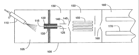
[0015] FIG. 1 is a symbolic depiction of an exemplary
mass analyzer system 100 utilizing the ion source
apparatus implemented in accordance with an embodiment of
the invention. Mass analyzer system 100 includes an
ionization chamber 105 into which a liquid sample is
introduced as a spray of electrically charged droplets
using an ion probe assembly 110. The liquid sample
consists of at least one analyte substance dissolved in
at least one solvent, and may take the form of the eluent
from a liquid chromatograph (LC) column. As will be
discussed in further detail hereinbelow, ion probe
assembly 110 may be advantageously provided with two gas
passageways through which first and second gas streams,
CA 02566862 2006-11-15
WO 2005/115888 PCT/US2005/017222
which respectively assist in the spray formation and
droplet desolvation processes, are directed into
ionization chamber 105.
[0016] A portion of the ions formed by desolvation of
the droplets and ionization of the analyte within
ionization chamber 105 flow under the influence of an
electric field into a first end 115 of sampling capillary
120. Sampling capillary 120 communicates via a second
end 125 thereof with a second chamber 130, which is
maintained at a lower pressure relative to ionization
chamber 105. The resultant pressure gradient causes ions
entering sampling capillary first end 115 to traverse
sampling capillary 120 and emerge into second chamber 130
via second end 125. According to the arrangement
depicted by FIG. 1, the central longitudinal axis of
sampling capillary 140 is angularly offset from the
central longitudinal axis of ion probe assembly 110 (and
of the droplet spray cone); however, the depicted
arrangement is presented only by way of a non-limiting
example, and mass analyzing systems employing an aligned
or orthogonal ion probe/sampling capillary geometry are
considered to be within the scope of the present
invention.
[0017] In accordance with the preferred embodiment,
sampling capillary 120 is controllably heated to ensure
complete evaporation of any remaining solvent associated
with partially desolvated droplets entering the sampling
capillary first end 115. Completion of the desolvation
process within sampling capillary 120 improves the ion
signal produced by mass analyzer and avoids operational
problems arising from the passage of partially desolvated
droplets into the low-pressure regions of mass analyzer
system 100. Heating of sampling capillary 120 may be
achieved by use of an annular resistance heater, disposed
within a capillary support block 135. An illustrative
example of a heated sample capillary assembly employing
6
CA 02566862 2006-11-15
WO 2005/115888 PCT/US2005/017222
an annular resistance heater is presented in U.S. Patent
No. 6,667,474 to Abramson et al., which is incorporated
by reference. The temperature of sampling capillary 120
is adjusted by appropriately varying the current supplied
to the heater. In some implementations of the invention,
the circuit supplying current to the heater may use a
feedback loop so that sampling capillary 120 can be
maintained at a target temperature. In typical
operation, sampling capillary 120 is heated to a
temperature in the range of 150 -400 C. Those skilled in
the art will recognize that the optimal temperature of
sampling capillary 120 will depend on various
considerations, including the liquid sample flow rate,
the temperature of ionization chamber 105, the droplet
size distribution of the spray cone, and properties of
the analyte solution.
[0018] Ions emerging from second end 125 of sampling
capillary 120 are centrally focussed by tube lens 140 and
subsequently pass via a skimmer 145 into a third chamber
150, which is maintained at a reduced pressure relative
to second chamber 130. A multipole lens assembly 155
disposed within third chamber 150 directs the ions from
the skimmer 160 into an analyzing chamber 165. A mass
analyzer, such as a quadrupole mass analyzer 170,
situated within analyzing chamber 165, filters the
entering ions according to their mass-to-charge ratio,
and an associated detector (not depicted) detects ions
passing through mass analyzer 170 and produces an output
representative of the incidence of ions having a
specified mass-to-charge ratio.
[0019] It will be appreciated that although a quadrupole
mass analyzer is depicted in FIG. 1 and described above,
the ion source apparatus may be used in connection with
any suitable type or combination of types of mass
analyzers, including without limitation time-of-flight
(TOF), Fourier transform (FTMS), ion trap, magnetic
7
CA 02566862 2006-11-15
WO 2005/115888 PCT/US2005/017222
sector or hybrid mass analyzers. It shota.ld also be
recognized that other ion sampling and ion guiding
configurations may be substituted for the sampling
capillary and ion transmission system described above
without departing from the scope of the invention. For
example, alternative configurations of the sampling
capillary include, but are not limited to, sample
apertures, orifices, non-conductive and semi-conductive
capillaries.
[0020] Aspects of the invention may be more easily
understood with reference to FIG. 2, which depicts a
fragmentary longitudinal cross-sectional view of ion
probe assembly 110. It is noted that FIG. 2 is intended
only as a symbolic representation and does not accurately
portray the relative or absolute dimensions of the ion
probe assembly components. Ion probe assembly 110 may
take the form of a two-part structure consisting of a
nozzle 205 releasably engaged (by cooperating threads or
other suitable measure) with a body 210. The two-part
configuration enables the easy and rapid
interchangeability of nozzles. Thus, the probe may be
supplied with multiple nozzles, wherein each nozzle has a
design optimized for a particular set of operating
conditions and analyte types, allowing the operator to
select and mount the appropriate nozzle for a particular
experiment. Additionally, the two-part configuration
facilitates cleaning and replacement of the nozzle
structure. Nozzle 205 is provided with a central axial
bore 215 through which a capillary tube 220 extends, and
first and second gas passageway end regions 225 and 230.
Capillary tube 220 extends rearwardly from nozzle 205
through a bore 245 defined in body 210 and terminates at
its rearward end in an inlet port coupled to the liquid
sample source, which may be the outlet of (for example)
an LC column. First and second gas passageways 235 and
240 within body 210 communicate, respectively, first and
second passageway end regions 225 and 230 in nozzle 205.
8
CA 02566862 2006-11-15
WO 2005/115888 PCT/US2005/017222
Gas flows are separately supplied to first and second gas
passageways 235 and 240 via inlet ports (not depicted)
located on ion probe assembly externally to ionization
chamber 105. A suitable configuration of sealing '
elements (not shown) may be disposed between nozzle 205
and body 210 to prevent leakage of the gas flows between
passageways 225/235 and 230/240.
[0021] In a preferred embodiment, nozzle 205 is
fabricated from a ceramic material such as silicon
nitride or aluminium oxide, which serves to electrically
isolate the high voltage (Oto 8kV) applied to the
electrospray capillary tube, which in this example is a
26 gauge stainless-steel tube encasing a fused silica
capillary tube, through which liquid is delivered to the
mass spectrometer, and the metal casing of the heat
exchanger assembly (grounded, OV or low voltage). Since
the heated auxiliary gas exits through the ceramic
nozzle, the material has to withstand high temperatures
without breakdown or out-gas chemical entities that can
contribute to chemical contamination. Furthermore, the
nozzle is easily replaceable for easy maintenance, and
experimentation with nozzles of different geometries.
[0022] Capillary tube 220 is preferably formed from a
metal or other conductive material so that it can be
maintained at a high positive or negative) voltage with
respect to nearby surfaces within ionization chamber 105
and thereby cause the droplets emitted from free end 255
to be electrically charged. The voltage may be applied by
a voltage source (not depicted) having a lead attached to
capillary tube 220 or to a conductive surface in
electrical communication therewith. The inner diameter of
capillary tube 220 will typically be in the range of 50-
500 pm, but may lie outside this range to accommodate
liquid sample flow and other operational requirements.
In the embodiment depicted in the figures, capillary tube
220 is surrounded by a sheath 265. The radially opposed
9
CA 02566862 2006-11-15
WO 2005/115888 PCT/US2005/017222
surfaces of capillary tube 220 and sheath 265 define
there between an annular region 270 through which a low-
surface tension sheath liquid (such as methanol,
acetonitrile, or 2-methoxyethanol) may be introduced.
The sheath liquid mixes with the liquid sample in a
mixing region located at the free end 255 of capillary
tube 220, thereby reducing its surface tension and
facilitating nebulization. This process is described in
greater detail in U.S. Patent No. 5,171,990 to Mylchreest
et al., the disclosure of which is incorporated by
reference. It should be recognized that the ion source
apparatus and method of the instant invention may be
practiced either with or without introduction of a sheath
liquid.
[0023] Nozzle 205 is adapted with a first gas passageway
end region 225 through which a first gas stream is
directed into ionization chamber 105. Referring to FIG.
3, which shows a front viewof nozzle 205, end region 225
will preferably have an annular cross section and be
located outwardly adjacent to sheath tube 265. As used
herein, the term "adjacent" means that the components
referred to are located proximally to one another, rather
than specifying immediate adjacence, i.e., two components
may be considered to be adjacent one another even if
other components are interposed therebetween. It should
be further noted that although FIG. 2 depicts capillary
tube 220 as being longitudinally coextensive with end
region 225, capillary free end 255 alternatively may be
longitudinally retracted or extended with respect to the
outlet of end region 225. The first gas stream emerging
from end region 225 will typically have a central
longitudinal axis (also referred to herein as the major
axis) that is substantially coincident with the central
longitudinal axis of capillary tube 220 and that of the
droplet spray cone emitted from free end 255.
CA 02566862 2006-11-15
WO 2005/115888 PCT/US2005/017222
[0024] In a preferred embodiment, the first gas stream
has a velocity at the capillary tube free end 255 that is
significantly below a characteristic nebulizing velocity.
The characteristic nebulizing velocity is the velocity at
which a gas stream exerts a strong shear force on the
incipient droplets emerging from capillary tube 220 (or
from sheath tube 265, if a sheath liquid is employed),
thereby removing the droplets from free end 255 and
altering the resultant droplet size distribution in the
spray cone. A typical nebulizing velocity will fall in
the range of 140-250 meters/second, although the velocity
will vary according to the capillary tube free end
dimensions and geometry as well as the properties of the
liquid sample. A more detailed discussion of the
nebulizing velocity is set forth in U.S. Patent No.
5,349,186 to Ikonomou et al., the disclosure of which is
incorporated by reference. The first gas stream will
preferably have a velocity well below the foregoing
range, for example on the order of 5 meters/second. At
this velocity, the first gas stream influences the
geometry of the spray cone (by obstructing the spreading
of the spray cone as droplets leave capillary tube 220)
and focuses the spray cone toward sampling capillary 120,
but does not participate in the droplet formation
process. In alternative embodiments, the first gas stream
has a velocity at or above the characteristic nebulizing
velocity. The first gas stream will typically consist of
nitrogen gas supplied from a pressurized source, although
other gases or combinations of gases having suitable
properties may be substituted.
[0025] Nozzle 205 is additionally adapted with second
gas passageway end region 230 through which a second gas
stream is directed into ionization chamber 105. The
second gas stream is heated to increase the rate at which
solvent is evaporated from the liquid sample droplets.
In a preferred configuration, the second gas stream is
introduced into ionization chamber 105 at a very low
11
CA 02566862 2006-11-15
WO 2005/115888 PCT/US2005/017222
velocity (typically around 0.1-2.5 meters/second). As
depicted in the figures, second passageway end region 230
is located at a greater radial distance from capillary
tube 220 relative to first passageway end region 225. In
the preferred embodiment, the second gas stream has a
longitudinal (major) that is substantially parallel to
the major axis of the first gas stream and spray cone.
Alternative embodiments may orient the major axis of the
second gas stream transversely with respect to the major
axis first gas stream or spray cone. However, in each
embodiment, the second gas stream is co-directional to
the first gas stream, i.e., the first and second gas
stream flow in the same lateral direction (left-to-right
in FIG. 1) toward sampling capillary 120. The co-
directional flow arrangement of the first and second gas
streams is in contradistinction to the counterflow or
"sweep flow" arrangement (disclosed, for example, in U.S.
Patent No. 5,157,260 to Mylchreest et al.) wherein a
drying gas flows through the ionization chamber in a
direction opposite to the direction of droplet travel.
The second gas stream will typically consist of nitrogen
gas supplied from a pressurized source, although other
gases or combinations of gases having suitable properties
may be substituted.
[0026] Referring again to FIG. 3, the outlet of second
passageway end region 230 may be arc-shaped or otherwise
radially asymmetric with respect to capillary tube 220,
i.e., it may be located in a preferred radial direction
relative to the capillary tube. In alternative
embodiments of the invention, end region 230 may have an
annular cross-section positioned radially outwardly of
first gas passageway end region 225. The outlet of the
second passageway end region 230 maybe configured in
several geometries, radially directed either
symmetrically or asymmetrically and is not limited to the
description in FIG. 3.
12
CA 02566862 2006-11-15
WO 2005/115888 PCT/US2005/017222
[0027] It should be further noted that although the
preferred embodiment locates second gas passageway 240
within ion probe assembly 110, other embodiments of the
invention may utilize a different arrangement wherein the
second gas passageway is formed in a structure that is
apart and separate from ion probe assembly 110. For
example, the second gas stream may be introduced into
ionization chamber 105 through a conduit that penetrates
the ionization chamber wall. In these embodiments, the
major axis of the second gas stream will still be co-
directional and preferably parallel to the major axis of
the first gas stream and droplet spray cone.
[0028] Ion probe assembly 110 is preferably provided
with a heat exchanger assembly 270 for heating the second
gas stream to the desired temperature. Under typical
operating conditions, the temperature of the second gas
stream is raised to between 75-150 C. Heat exchanger
assembly 270 includes an annular resistance heater 275
located in interior of the ion probe assembly body 210.
Annular resistance heater 275 has a cylindrical interior
bore through which capillary tube 220 and first gas
passageway 235 extend. The amount of heat produced by
resistance heater 275 (and consequently the amount of
heat transferred to the second gas stream temperature) is
controlled by adjusting the voltage applied to the heater
by a voltage source (not depicted) in electrical
communication with the heater. An annular heat exchanger
block 280, fabricated from a thermally conductive
material is machined in a manner so as to facilitate the
auxiliary gas stream to spiral as it is forced forward in
an attempt to maximize contact with as much surface area
as possible and arranged in thermal communication with
heater 275. Heat generated by heater 275 is transferred
(by radiative, convective and/or conductive modes) to
heat exchanger block 280, which in turn heats the second
gas stream Spiral pathway 285 provides sufficient
contact area between heat exchanger block 280 and the gas
13
CA 02566862 2006-11-15
WO 2005/115888 PCT/US2005/017222
flowing through second gas passageway 285 to heat the gas
to the target temperature range.
[0029] While heating of the second gas stream is
desirable to promote droplet desolvation, it is generally
undesirable to significantly raise the temperature of the
liquid sample flowing through capillary tube 220, since
doing so may cause thermal decomposition of the
analyte(s). To minimize heat transfer from heat
exchanger assembly 270 to the liquid sample, several
insulative features are placed between heater 275 and
capillary tube 220. As depicted in FIG. 4, which shows a
lateral cross-sectional view taken through ion probe
assembly body 210, the insulative features include a
ceramic insulator tube 290 radially interposed between
heater 275 and capillary tube 220. Conductive heat
transfer between heater 275 and the liquid within
capillary tube 220 is further inhibited by the gaps
between heater 275 and ceramic insulator tube 290, and
between ceramic insulator tube 290 and sheath 265, and
between sheath 265 and capillary tube 220. Other
features may be substituted or added to effect the
objective of minimizing heat transfer to the liquid.
[0030] Those skilled in the art will recognize that
other techniques for heating the second gas stream may be
substituted for the technique described above. For
example, the second gas stream may be passed through an
external heat exchanger prior to admitting the gas stream
into the second gas passageway.
[0031] It is to be understood that while the invention
has been described in conjunction with the detailed
description thereof, the foregoing description is
intended to illustrate and not limit the scope of the
invention, which is defined by the scope of the appended
14
CA 02566862 2006-11-15
WO 2005/115888 PCT/US2005/017222
claims. Other aspects, advantages, and modifications are
within the scope of the following claims.