Note: Descriptions are shown in the official language in which they were submitted.
CA 02567014 2006-11-01
POSITIVE-DISPLACEMENT SAMPLING APPARATUS
FIELD OF THE INVENTION
This invention is related generally to. apparatus for extracting samples of
liquid
from vessels, and in particular to positive-displacement sampling apparatus
with an
inline valve.
BACKGROUND OF THE INVENTION
There is a need with many manufacturing operations and processes and within
liquid transportation systems to monitor the composition or other properties
of the
liquid material which is either contained in or flowing within a vessel. Often
what is
required is to capture a sample of the liquid from within the vessel in order
to make
the necessary measurements. It is most desirable to be able to capture such
samples
without interference with or contamination to the processes being monitored.
Non-
interference with a process is often achieved by ensuring that vessel pressure
is
maintained throughout the sampling-capturing operation. Further, it is often a
requirement that samples be taken at regular and frequent intervals so that
reliability,
operator safety, and sampler maintenance and longevity are important
requirements
for such samplers.
A number of samplers which are used in such manufacturing or process
applications are devices which capture small, discrete samples of liquid. An
example
of such a sampler is disclosed in United States Patent No. 6,792,818 by Ben E.
Jaeger.
This positive-displacement sampler includes a plunger having a sample
receiving
recess and a connecting device which couples the sampler to a vessel at an
aperture in
the vessel. The sampler is attached to the connecting device, and the
connecting
device is moveable between a first position placing the sampler into, and a
second
position taking the sampler out of communication with the aperture. With the
connecting device in the first position, the plunger is reciprocated to extend
the
plunger and its recess through the connecting device and vessel aperture into
product
in the vessel to receive a product sample in the recess. The plunger is then
retracted
-1-
CA 02567014 2006-11-01
i = =
from the vessel and through the connecting device to deliver the product
sample to a
collection point. During reciprocation of the plunger, a liquid seal is
maintained
between the vessel interior and sample collection point, and when the
connecting
device is moved to the second position, the sampler can be detached from the
connecting device for service or repair, without escape of liquid from the
vessel
through the connecting device.
Particularly severe requirements exist for samplers used in applications where
the liquid being sampled contains a solid phase. An example of this is in the
handling
of oil sands in which the liquid may contain bituminous sand, oil, hot water,
and
possibly clay. The solid phase is the source of abrasive material which
creates a
particularly difficult operational environment for samplers. The abrasive
material can
become trapped in regions around seals, particularly when elements within the
sampler become misaligned due to, for example, frictional forces during
movement of
sampler elements, thereby allowing the abrasive material to flow by leakage
into areas
in which it is not intended to be, causing excessive wear. Also, when seals
move past
entry and exit interfaces within valves and other elements within a sampler,
abrasive
material can easily cause the seals to wear far too rapidly, necessitating
frequent and
costly maintenance on the sampler.
The sampler disclosed in United States Patent No. 6,792,818 described above,
when applied in applications such as oil sands, operates in a manner in which
excessive seal/interface traverses and misalignment are both causes of seal
wear. As
an example, in the sampling of such abrasive liquids, sampling frequencies may
be as
high as five samples per hour and may result in seals being replaced as often
as once
each week, creating an extremely high maintenance cost.
Another desirable and intended feature for samplers is the ability to be able
to
achieve what is termed "double block and bleed" capability, the ability to
isolate the
sampler from vessel pressure and to verify that such isolation has indeed
taken place
so that the sampler can be disconnected. If seals are woin and misalignment
causes
farther leakage, the sampler cannot be relied on to achieve the required
isolation. The
invention disclosed in the '818 patent can exhibit such unwanted behavior when
the
ball valve, which is "floating" within a set of seals, becomes misaligned and
causes
-2-
CA 02567014 2006-11-01
~ ' . .
leakage of unwanted vessel pressure, thereby causing a potentially unsafe
condition
for an operator performing maintenance on the sampler or simply taking a
sample in
the course of regular vessel monitoring.
United States Patent No. 5,905,213, also by Ben E. Jaeger, discloses a sampler
in which the forward end of the sampler housing is coupled to a movable valve
for
movement with the valve, and the housing and valve have axially-aligned bores.
Movement of the valve places the forward end of its bore into and out of
communication with an opening in a vessel containing the liquid to be sampled.
A
plunger in the housing bore has a sample-receiving recess intermediate its
ends, and
with the forward end of the valve bore placed into communication with the
interior of
the vessel, the plunger is reciprocated forward in the housing and valve bores
to
proj ect the recess into the vessel to receive a product sample therein. The
plunger is
then reciprocated rearward to retract the product sample containing recess
from the
vessel and through the valve and housing bores to a sample collection point in
the
housing. When repair or replacement of the sampler is required, the valve is
moved to
place the forward end of the valve bore out of communication with the vessel
interior,
whereupon the sampler housing can be disconnected from the valve without
outflow
of liquid product from the vessel through the valve bore. A disadvantage of
the
arrangement is that the entirety of the sampler moves conjointly with movement
of the
valve between its open and closed positions, so a relatively large
unobstructed area
must be provided around the sampler to accommodate such movement, which limits
freedom of location of the sampling apparatus. In addition, to accommodate
mounting
of the sampler housing on the valve, the valve must be relatively large to
accommodate connection of the sampler housing to it, resulting in increased
manufacturing costs.
Existing samplers currently used as described above fall short of
delivering effective, safe and cost-effective sampling. Thus, there is a need
for a
sampler which satisfies the objectives as set forth in the following section.
-3-
CA 02567014 2006-11-01
OBJECTS OF THE INVENTION
It is an object of this invention, in the field of process sampling
technology, to
provide an improved sampler which incorporates the isolation valve within the
sampler apparatus.
Another object is to provide a sampler which deposits the liquid sample from a
location within the valve of the sampler.
Another object of the present invention is to provide a sampler which can be
used with abrasive liquids.
Another object of this invention is to provide a sampler which minimizes wear
on seals within the sampler.
Another object of this invention is to provide a sampler which minimizes
leakage at the seals within the sampler.
Another object of this invention is to provide a sampler with a valve in which
valve core is completely encapsulated by its trunnion supports and, further,
in which
the valve core and stem are structurally integral.
Another object of this invention is to provide a sampler which reduces the
number of times seals traverse across interfaces within the sampler during the
sampling process.
A further object of this invention is to provide a sampler which protrudes a
reduced length from the vessel and thus also has reduced weight.
It is an object of this invention to provide a sampler with "double-block-and-
bleed" capability with a single valve.
It is also an object of this invention to provide a sampler with improved
operator safety.
Still another object of the invention is to provide a sample which m;nimizes
misalignment within the valve.
Yet another object of the invention is to provide a sampler with a valve which
is less sensitive to any nnisalignment that may occur within the valve.
These and other objects of the invention will be apparent from the following
descriptions and from the drawings.
-4-
CA 02567014 2006-11-01
SUMMARY OF THE Il\fVENTION
The invention is an improvement in apparatus for withdrawing a liquid sample
from a vessel. Such apparatus is affixed to the vessel and has (a) a plunger
forming a
sample-receiving space movable from the vessel interior to and beyond a sample-
delivery site and (b) a valve for closing the vessel when the plunger is
beyond the
sample-delivery site. The improvement of the instant invention comprises the
sample-
delivery site being incorporated in the valve.
In some preferred embodiments of the invention, the valve is a trannion valve
and the valve has a stem and a central portion, the central portion dividing
the stem
into a first stem portion and a second stem portion and having a through-hole
with an
axis substantially perpendicular to the stem axis. In highly preferred
embodiments,
the first stem portion includes a discharge/bleed port aligned substantially
along the
axis of the stem for discharge of the sample from the sample-receiving space
when
such space is at the sample-delivery site. Further, the plunger in some highly
preferred embodiments passes through the through-hole to receive a sample from
the
vessel interior and to deliver the sample to the discharge/port.
In some preferred embodiments, the through-hole in the central portion of the
valve is a clearance hole for the plunger, and in some preferred embodiments,
the
second stem portion includes a purge/flush inlet pork
In highly preferred embodiments of the inventive sampling apparatus, the
valve includes first and second valve seats that form stem-engagement surfaces
for the
first and second stem portions, respectively, and that together form a central
portion
engagement surface. In such embodiments, the first and second valve seats
together
surround, support and seal the central portion and the first and second stem
portions.
In some embodiments, the plunger moves within first and second axially-
aligned plunger cylinders, (a) the first on the vessel side of the valve and
the second
on the opposite side of the valve, (b) the sample-receiving space is an
annular space,
and (c) the plunger includes first and second plunger seals each mounted
beyond a
respective end of the sample-receiving space and spaced such that when the
sample-
receiving space is at the sample-delivery site, the first and second plunger
seals are
engaging the first and second plunger cylinders, respectively.
-5-
CA 02567014 2006-11-01
In highly preferred embodiments, the valve is a ball valve. In other
embodiments, the valve is a plug valve. Further, some embodiments include a
compound actuator for plunger movement.
Highly preferred embodiments of the inventive sampling apparatus include a
bleed valve to effect collection of the sample from the discharge/bleed port.
The term "liquid" as used herein, in addition to the common usage of the term,
also includes liquids which contain a solid phase, such as is the case with a
mixture of
oil, water and sand.
The term "vessel" as used herein refers to any sort of enclosure containing
the
liquid which is to be sampled. Thus, a vessel as so defined includes a pipe or
other
conduit through which the liquid flows as well as any container such as a
process
reactor which is holding the liquid to be sampled.
The term "clearance hole" as used herein refers to a hole which is sized such
that the object which is referenced thereto is able to pass through or be
contained in
the hole without touching the walls of the hole.
The term "sample withdrawal" or related terminology as used herein refers to
the process by which a sample of liquid is removed from a vessel and
subsequently
delivered to a desired sample location.
The term "compound actuator" as used herein refers to a pneumatic or
hydraulic actuator (containing a primary piston and a cylinder) which also
contains a
secondary piston such that the primary and secondary pistons cooperate to
effect the
movement of the object being moved by the actuator.
BRIEF DESCRIPTION OF THE DRAWINGS
The drawings illustrate preferred embodiments which include the above-noted
characteristics and features of the invention. The invention will be readily
understood
from the descriptions and drawings. In the drawings:
FIGURE 1 is a perspective drawing of one embodiment of the inventive
sampling apparatus.
FIGURE 2 is a cutaway perspective drawing of the sampling apparatus of
FIGURE 1 with the sample-receiving space between the vessel interior and the
-6-
CA 02567014 2006-11-01
sample-delivery site and within the front sleeve.
FIGURE 3 is a cutaway perspective drawing of the sampling apparatus of
FIGURE 1 with the sample-receiving space in the vessel interior.
FIGURE 4 is a cutaway perspective drawing of the sampling apparatus of
FIGURE 1 with the sample-receiving space at the sample-delivery site.
FIGURE 5 is a cutaway perspective drawing of the sampling apparatus of
FIGURE 1 with the sample-receiving space beyond the sample-receiving site and
with
the ball valve in a closed position.
FIGURE 6 is a cutaway perspective drawing of the plunger of the sampling
apparatus of FIGURE 1.
FIGURE 7 is a cutaway perspective drawing of the sampling apparatus of
FIGURE 1 with the valve portion and the actuator portion separated for
maintenance.
FIGURE 8 is a cutaway perspective drawing of the valve of the sampling
apparatus of FIGURE 1, the plane of the cutaway being perpendicular to the
cutaway
plane of FIGURES 2-5. The valve is in a closed position, and the bleed valve
is in a
closed position.
FIGURE 9 is a cutaway perspective drawing of the valve of the sampling
apparatus of FIGURE 8 with the valve in an open position, and the bleed valve
is in
an open position.
FIGURE 10A is a cross-sectional drawing of the stem, central portion and the
seat of a ball valve.
FIGURE lOB is a cutaway perspective drawing of a seat for the ball valve of
FIGURE 9a.
FIGURE 10C is a cross-sectional drawing of the stem and central portion and
the seat of a plug valve. The central portion is a truncated cone.
DETAILED DESCRIPTION OF PREFERRED EMBODIlVIENTS
FIGURE 1 is a perspective drawing of sampling apparatus 10. FIGURES 2-5
and 7-9 are all cutaway perspective drawings of sampling apparatus 10 with the
elements of apparatus 10 in different positions illustrating its operation.
(To reduce
the crowding of reference numbers, not all elements of sampling apparatus 10
are
-7-
CA 02567014 2006-11-01
labeled in every figure.) Referring to FIGURES 1-5, sampling apparatus 10 has
a
valve portion 12 and an actuator portion 14. Sampling apparatus 10 is affixed
by
adapter 16 to a vessel 1 (shown in FIGURES 2-5) which contains the liquid (not
shown) to be sampled through an adapter opening 18 (shown in FIGURES 2-5).
Sampling apparatus 10 also includes a bleed valve 20 attached to valve portion
12 for
the purpose of assisting in the collection of a sample taken by sampling
apparatus 10.
Referring now to FIGURES 2-5 and FIGURES 8-9, valve portion 12 of
sampling apparatus 10 includes valve 11 which has a valve body 22 containing a
valve stem 24 and a central valve portion 26. Stem 24 is divided into two
portions, a
first stem portion 24a and a second stem portion 24b, by central valve portion
26, thus
forming the stem and central valve portion of a trunnion valve. Central valve
portion
26 is a spherical structure and has a through-hole 26h (best seen in FIGURES
5, 8 and
9) with an axis substantially perpendicular to the axis of stem 24; thus valve
11 in this
embodiment is a ball valve. Through-hole 26h forms the sample-delivery site of
sampling apparatus 10.
FIGURES l0A and l OB more clearly illustrate some of the details of stem 24
and central portion 26. Stem 24 and central portion 26 are surrounded,
supported and
sealed by a first valve seat 28a and a second valve seat 28b. First and second
valve
seats 28a and 28b engage first and second stem portions 28a and 28b
respectively at
first and second stem-engagement surfaces 30a and 30b and together engage
central
portion 26 at a central-portion-engagement surface 30c. First and second valve
seats
28a and 28b thus ensure that stem 24 and central valve portion 26 remain in
proper
alignment within valve 11.
Referring now to FIGURES 8 and 9 for farther detail with respect to valve
portion 12, first stem portion is partially supported by valve body 22 at a
support
surface 32 and by a set of gland seals 34s. Primary support for stem 24 and
central
portion is provided by seats 28a and 28b. First and second stem-engagement
surfaces
30a and 30b thus form trunnion supports for first and second stem portions 24a
and
24b within valve 11. Gland 34 is held in place by a bevel washer spring 36,
and a
paclcing bolt 38 is tightened into a threaded portion 40 of valve body 22 to
complete
the internal assembly of valve 11. Valve handle 42 is attached to stem 24 to
effect
-8-
CA 02567014 2006-11-01
turning of valve 11.
First stem portion 24a includes an axially-aligned sample discharge/bleed port
44. Port 44 is open to through-hole 26h, the sample-delivery site, thus
enabling
sample liquid to flow through first stem portion 24a into bleed valve 20 and,
as
desired, into a collection container (not shown) which may be connected to
bleed
valve sample port 54.
Second stem portion 24b includes a purge/flush inlet port 46. Port 46 includes
axial passage 46a and intersecting passage 46b. Passage 46a is aligned axially
with
stem 24, and passage 46b intersects passage 46a in order to enable flow in
port 46 to
reach a pair of annular gland passages 48a and 48b which are connected
together by a
connecting passage 50. Annular gland passage 48b is aligned with an external
flush
port 52 (shown on FIGURES 1, 8 and 9). Thus, a flow passage exists in valve 11
between port 52 and through-hole 26h to effect purging and flushing of valve
11
regardless of the position of stem 24 of valve 11.
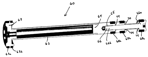
FIGURE 6 is a cutaway perspective drawing of a plunger 60 of sampling
apparatus 10. The various elements of plunger 60 can be seen in FIGURES 2-5
but
are most easily seen in FIGURE 6. Plunger 60 is assembled from a number of
plunger
elements. Plunger 60 includes a plunger tube 62 welded to plunger adapter 64
at one
end of tube 62 and a rear piston 63 welded at the other end of tube 62.
Adapter 64
includes a threaded hole 65 into which a mandrel 66 is inserted. Rear piston
63
includes rear piston seals 63a and 63b.
Mandrel 66 includes a mandrel head 66a and a mandrel shaft 66b. Onto
. mandre166 are assembled, in sequence, a front sea168a, an 0-ring 74 (all 0-
rings in
this assembly are labeled with reference number 74 as similar elements), an
annular
spacer 70, an 0-ring 74, a middle seal 68b, an 0-ring 74, and a rear spacer
72.
Annular spacer 70 forms the sample-receiving space of sampling apparatus 10. A
rear
seal 68c is placed onto plunger adapter 64, and mandrel 66 is inserted into
threaded
hole 65 in adapter 64, completing the assembly of plunger 60. Mandre166 is
thus
configured to enable easy disassembly and assembly to facilitate replacement
of the
seals on plunger 60.
-9-
CA 02567014 2006-11-01
Referring again to FIGURES 2-5, plunger 60 is slidably assembled into a rear
sleeve 76 which is connected to valve body 22. Plunger 60 slides within sleeve
76,
through through-hole 26h when stem 24 is in position to allow plunger 60 to
enter
hole through-hole 26h, and into and partially through a front sleeve 78
mounted in
adapter 16 and body 22. 0-rings 80 provide seals for plunger 60 within front
sleeve
78 as shown. Rear sleeve 76 and front sleeve 78 form a pair of first and
second
axially-aligned plunger cylinders in which plunger 60 moves. The first plunger
cylinder, front sleeve 78 is on the vessel side of valve 11, and the second
plunger
cylinder, rear sleeve 76, is on the opposite side of valve 11.
A front piston 82 is slidably assembled onto the outside of rear sleeve 76,
into
a front cylinder 84, and into a rear cylinder 86 such that front piston 82
slides within
both front cylinder 84 and rear cylinder 86. Rear piston 63 of plunger 60 is
also
slidably assembled into rear cylinder 86. Front piston 82 includes -a forward
piston
portion 82a and an aft piston portion 82b. Aft portion 82b includes a front
piston
sleeve bearing 88 in which plunger 60 slides, and rear sleeve 76 includes two
rear
sleeve seals 76a and 76b between which is an annular slot 92 connected to an
intermediate drain/vent port 94 open to the outside of valve 11. The purpose
of slot
92 and port 94 is that if seal 76a were to leak, liquid from sampling
apparatus 10
would not find its way into rear cylinder 86 but rather simply flow through
port 94 to
the outside. Forward piston portion 82a includes two seals 85a and 85b for
slidable
support of front piston 82 within front cylinder 84.
Front cylinder 84 includes a center head 90 which forms the connection
between front cylinder 84 and rear cylinder 86. Affl piston portion 82b
includes an air
passage 83 to allow air flow through aft piston portion 82b when front piston
82 is
sliding with respect to rear sleeve 76.
Rear cylinder 86 includes a rear head 95 which closes off rear cylinder 86.
Rear head 95 includes seals 96 which seal between rear head 95 and a stop tube
98
assembled into a threaded hole 100 in rear head 95 with a wing nut 102. Stop
tube 98
functions to provide an air passage for displaced air when plunger 60 moves
within
rear cylinder 86. Stop tube 98 with a stop washer 99 mounted thereon also
functions
as a stop for plunger 60 as described below.
-10-
CA 02567014 2006-11-01
Front piston 82, front cylinder 84, rear piston 63 and rear cylinder 86, with
their attendant seals, constitute a compound pneumatic actuator for effecting
the
movement of plunger 60 into the various positions required by sampling
apparatus 10.
Plunger 60 could be actuated by numerous other types of actuators including
but not
limited to simple pneumatic actuators, hydraulic actuators, and various
electromechanical actuators.
FIGURES 2-5 illustrate four different positions of the plunger within sampling
apparatus 60. These four positions constitute the specific positions which
best
describe the process of liquid sample withdrawal from vessel 1. Actuator
portion 14
of sampling apparatus 10 moves plunger 60 to and from the various positions in
order
to effect sample withdrawal. FIGURE 6 illustrates sampling apparatus 10
separated
into valve portion 12 and actuator portion 14. In FIGURE 6, wing nut 102 has
been
unscrewed to release stop tube 98, placing plunger 60 in a maintenance
position. In
this position, stop tube 98 can be used to push mandrel 66 out of rear sleeve
76,
making it available for removal and replacement of seals 68a-68c as required
or any
other maintenance which may be required.
FIGURE 2 illustrates plunger 60 of sa,mpling apparatus is the "parked"
position, a position placing mandrel head 66a in a position to protect front
sleeve 78
and mandrel head 66a from damage caused by abrasive liquid flowing in vessel
1. In
this position, front piston 82 has been moved away from valve 11 to a position
stopped by center head 90. To reach this position, actuator air is applied to
a piston-
park port 108 causing front piston 82 to move away from valve 11. Center head
90
provides a stopping position for front piston 82 which serves as a stop for
rear piston
63.
FIGURE 3 illustrates plunger 60 of sampling apparatus 10 in position to
receive a liquid sample from within vessel 1. Valve stem 24 is in position to
align
through-hole 26h such that plunger 60 may pass through central valve portion
26. In
this sample-receiving position, the sample-receiving site formed within
annular spacer
70 is open to capture liquid flowing through or being processed within vessel
1. In
this position, both front piston 82 and rear piston 63 are positioned as close
to valve
11 as possible within their respective cylinders. To reach this position,
actuator air is
-11-
CA 02567014 2006-11-01
applied to a piston-apply port 104 causing pistons 63 and 82 to move toward
valve 11.
From the sample-receiving position, the fixed volume of liquid in the sample-
receiving space is then moved through adapter opening 18 and through front
sleeve 78
into through-hole 26h which forms the sample-delivery site. This sample-
delivery
position of sampling apparatus 10 is illustrated in FIGURE 4. In the sample-
delivery
position, rear piston 63 is moved within rear cylinder 86 until it reaches
stop washer
99 on stop tube 98. Stop washer 99 is positioned to place annular spacer 70 in
the
sample-delivery site within through-hole 26h in central valve portion 26. To
reach
this sample-delivery position, actuator air is applied to piston-retract port
106 to move
rear piston 63 to its stop position created by stop washer 99.
In the sample-delivery position, bleed valve 20 can be used to effect transfer
of
the liquid sample contained in the sample-receiving space to a sample
container (not
shown) which may be connected to bleed valve 20 at bleed valve sample port 54.
FIGURE 8 illustrates bleed valve 20, a ball valve in this embodiment, in the
closed
position while sampling apparatus also in a closed position, indicating that
sampling
apparatus 10 is in a position ready for or undergoing maintenance as
illustrated in
FIGURES 5 and 6, respectively. FIGURE 9 illustrates bleed valve 20 in an open
position with valve 11 also in an open position, thereby allowing a liquid
sample to
pass from the sample-delivery site in through-hole 26h, through bleed valve 20
and
into a sample container (not shown). Bleed valve 20 is attached to first stem
portion
24a such that when valve 11 is turned using valve handle 42, the entire bleed
valve 20
turns with stem 24.
FIGURE 5 illustrates sampling apparatus in a maintenance position, ready for
separation of actuator portion 14 from valve portion 12 as illustrated in
FIGURE 6.
To reach this position, wing nut 102 is removed from rear head 95 thereby
allowing
stop tube to move stop washer 99 away from valve 11 and thus allowing plunger
60 to
be removed from valve 11 completely. With the stop washer 99 back against rear
head 95, actuator air applied to piston-retract port 106 causes rear piston to
move
farther back into rear cylinder 86.
A position called a"double-block-and-bleed"position is illustrated in
FIGURE 5. With sampling apparatus in a position ready for maintenance, an
operator
-12-
CA 02567014 2006-11-01
is able to use external flush port 52 in combination with bleed valve 20 to
ensure that
valve 11 has been properly closed, thus isolating vessel l from sampling
apparatus 10,
before sampling apparatus 10 is removed. In this position, it is also possible
to ensure
that the sample has been properly removed from the sample-delivery site in
through-
hole 26h This position of sampling apparatus 10 thus provides safety for the
operator
during operation of sampling apparatus 10.
The selection of materials to be used for the embodiment described herein
follows sound engineering practice as known by those skilled in the state-of-
the-art of
process monitoring, chemical instrument design or mechanical design. In
general,
parts within the embodiment described herein may be made of stainless steel
such as
316SS but are not limited to being made of stainless steel. Seal materials for
0-rings
can be but are not limited to commercially-available 0-ring materials such as
Viton
or nitrile, both known to those skilled in the art of mechanical design.
Seals such as rear sleeve seals 76a and 76b maybe made of PTFE
(polytetrafluoroethylene) well known to those slrilled in the art of
mechanical design.
Valve seats 28a and 28b may be made of TFMTM, a modified PTFE material also
well
known to those skilled in the art of mechanical design. In some applications,
front
sleeve 78 may be required to withstand an highly-abrasive environment. In such
cases, it may be useful to make front sleeve 78 from a material such as
tungsten
carbide. This and other materials are well-known to those skilled in the art
of
mechanical design. Front piston sleeve bearing 88 may be made of an
appropriate
sleeve bearing material such as silicon bronze or an oil- or PTFE-impregnated
bearing
material such as is well-known by those skilled in the art of mechanical
design.
Front piston 82, front cylinder 84, rear piston 63, rear cylinder 86, center
head
90, and rear head 95 all may be made out of aluminum.
None of material suggested herein are meant to be limiting to the scope of the
present invention.
FIGURE lOC illustrates an alternative embodiment for stem 24 and central
valve portion 26. In FIGURE l OC, central valve portion 26 is a truncated
cone; a
large end 26a of conical central valve portion 26 is adjacent to second stem
portion
24b and a small end 26b of conical central valve portion 26 is adjacent to
first stem
-13-
CA 02567014 2006-11-01
portion 24a.
Referring to FIGURE 3, when, for example, front sea168a on mandrel head 66
of plunger 60 enters front sleeve 78 from vessel 1, sea168a moves across a
boundary
between being unconstrained and being constrained (fitting tightly) within
front sleeve
78. Such a transition is called a seal/interface encounter. Each such
encounter is an
opportunity for any abrasive solid phase in the liquid from vessel 1 that is
carried by
the seal to cause wear of the seals. One significant advantage of placing the
sample-
delivery site within valve 11 is that there are fewer such encounters during a
sample
withdrawal cycle than with sampling apparatus of the prior art such as that
described
in United States Patent No. 6,792,818 mentioned above. If the sample-receiving
space was moved to a sample-delivery site on the side of valve opposite to
vessel 1 as
in Jaeger '818, several additional wear-causing encounters would occur,
thereby
reducing the life of the seals as compared to those in the present invention.
Furthermore, through-hole 26h is a clearance hole, i.e., larger in inside
diameter
compared to the outside diameters of front seal 68a, middle seal 68b, and rear
seal 68c
on mandrel 66 such that these seals do not touch the walls of through-hole 26h
and
such that any solid phase particles in the liquid being sample will not be
pressed into
these seals while sampling apparatus 10 is the sample-delivery position. In
spite of
the fact that first and second valve seats 28a and 28b ensure that stem 24 and
central
valve portion 26 remain in proper alignment within valve 11, through-hole 26h,
being
a clearance hole, also reduces the effect of any misalignment which may occur
within
valve 11 during the operation of sampling apparatus 10.
While the principles of this invention have been described in connection with
specific embodiments, it should be understood clearly that these descriptions
are made
only by way of example and are not intended to limit the scope of the
invention.
-14-