Note: Descriptions are shown in the official language in which they were submitted.
CA 02567019 2006-11-01
ANGULAR SPRAY NOZZLE FOR
GAS DYNAMIC SPRAY MACHINE
The present invention relates to particulate spray guns. More
specifically, the invention pertains to a nozzle extension for a supersonic
particulate spray machine for conveying the high speed particles to a
workpiece surface which is not disposed in the line of sight of the spray
machine's normal output.
Supersonic gas dynamic spray (GDS) technology has proven highly
efficient for applying dense coatings to various flat workpiece surfaces.
There is a great demand in industry for cost effective application of such
dense coatings on inside cylindrical surfaces of elements such as engine
blocks, tubes, pipes and artillery gun barrels to enhance the wear
resistance of components resident inside such cylindrical openings and to
provide corrosion resistance to protect such surfaces from attack by
materials flowing through the cylindrical passages of such elements.
Applying the GDS technology to such cylindrical interior surfaces has
presented problems in the past, because GDS is basically a line-of-sight
process. Known angled extensions for GDS nozzles suffer from clogging
problems which tend to manifest themselves in extremely short time
periods, thereby substantially increasing the cost of arising from frequent
required replacement.
1
CA 02567019 2006-11-01
Therefore there is seen to be a need in the art for a nozzle
extension having an output angled away from the longitudinal center line
of the output of the spray machine nozzle and capable of resisting
clogging and maintaining the velocity of the accelerated particulates above
a critical speed allowing for formation of dense coatings.
A nozzle extension for use with a nozzle of a particulate spray
machine includes a substantially linear hollow input section having an
input end and an output end, the input end adapted to be coupled to the
nozzle, the input section having a longitudinal axis and an input section
inner diameter. A hollow curvilinearly angled output section of the
extension has an input end coupled to the output end of the input section
and an output end adapted for discharging particulate spray toward a
workpiece surface. A longitudinal axis of the input end of the output
section is substantially aligned with the longitudinal axis of the input
section. The longitudinal axis of the output end of the output section
extends at a non-zero angle to the longitudinal axis of the input section,
and the output section has an output section interior diameter greater than
the input section interior diameter.
Further areas of applicability of the present invention will become
apparent from the detailed description provided hereinafter. It should be
understood that the detailed description and specific examples, while
indicating the preferred embodiment of the invention, are intended for
2
CA 02567019 2006-11-01
purposes of illustration only and are not intended to limit the scope of the
invention.
The present invention will become more fully understood from the
detailed description and the accompanying drawings, wherein:
Figure 1 presents a partially cross sectioned side view of a nozzle
extension arranged in accordance with the principles of the invention;
Figure 2 sets forth perspective views of two different extension
elements for a supersonic nozzle having different angled outputs, each
arranged in accordance with the principles of the invention; and
Figure 3 is a block diagram of a gas dynamic spray machine
system suitable for use with the nozzle extension of the invention.
Gas dynamic spraying uses a supersonic converging/diverging (de
Laval-type) nozzle. A heated, high pressure carrier gas is supplied
upstream of the converging portion of the nozzle and the powdered
particulate material is introduced into the carrier gas stream in the nozzle.
Coatings are produced by entraining metal powders in an accelerated air
stream through a supersonic nozzle and projecting them against a target
substrate, normally as close to a 900 angle as possible. It is believed that
for the particulate matter to adhere to a substrate, they must break the
oxide shell on the substrate material permitting subsequent metallurgical
bond formation between plastically deformed particles and the substrate.
3
CA 02567019 2006-11-01
It is imperative for the accelerated particles to exceed a critical velocity
prior to their being able to bond successfully with the substrate.
One suitable form of a gas dynamic spray system 300 is set forth in
block diagram form in Fig. 3. Gas supply 310 creates a moving stream of
carrier gas 316 which passes through a heater element 314 and enters a
nozzle 302. Powder hoppers 304a and 304b are coupled to nozzle 302
via powder supply line 320. A pressure sensor 312 monitors pressure in
supply line 320 and provides an indication thereof to a controller 308.
Controller 308, in turn, has feedback control connections 324 to powder
hoppers 304a and 304b. For applying the particulate matter to a
workpiece surface or substrate which is not extending at substantially a
right angle to the axis of the output of nozzle 302, an extension 100
arranged in accordance with the invention is utilized. The details of
extension 100 will be set forth in a later section of this description.
Multiple powder hoppers 304a, b provide different desired powder
compositions for different applications to powder inlet 318 of nozzle 302.
Heater element 314 heats the gas to a temperature less than the melting
point of the powder. Powder compositions from powder hoppers 304a
and 304b are directed into nozzle 302 due to negative pressure created at
the point of injection 318. The nozzle 302 propels the powder particles
which are deposited atop a substrate as a bulk build-up of material.
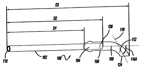
With reference to Fig. 1, details of an exemplary nozzle extension
100 are set forth. It is to be understood that such a nozzle can be used in
4
CA 02567019 2006-11-01
any type of gas dynamic spray system--not just to the exemplary system
300 described above. Nozzle extension 100 has an input section 102
which extends substantially linearly along a longitudinal axis 108. Section
102 is hollow and has an inner diameter for passage of the particulate
matter to be dispersed. Section 102 has an input end 118 adapted to be
coupled to the output of a supersonic nozzle.
An output end 120 of input section 102 is in fluid communication
with the interior of a curvilinear output section 106 of extension 100. The
extension of Fig. 1 shows input section 102 being coupled to output
section 106 via a threaded connection extending inside of section 106.
However, it will be apparent to those skilled in the art that a variety of
means could be utilized for coupling section 102 to 106, including forming
the entire extension as a unitary piece.
Output section 106 has an input end with a longitudinal axis
substantialiy aligned with axis 108 of the input section 102. Output section
106 has a longitudinal axis 110 at its output 124 which extends at a
non-zero angle to axis 108. This angle A, or 114, is shown in Fig. 1
between axis 108 of input section 102 and axis 110 of the output end of
output extension section 106.
The internal diameter of the hollowed portion of curvilinear section
106 is larger than that of input section 102. The resultant shape of the
interior of section 106 induces peripheral turbulence in the particulate flow
entering section 106 from output end 120 of section 102, thereby inhibiting
CA 02567019 2006-11-01
adhesion of the particles to the interior surface of curvilinear section 106
as well as erosion of curvilinear section 106. Hence, clogging and erosion
are minimized, or at least substantially delayed, with this design.
Angle A of Fig. I could range from just above 00 to about 90 where
the output of the extension is substantially perpendicular to longitudinal
axis 108. A more preferred range of angle A is between about 10 and
about 80 .
As stated previously, the internal diameter of the hollow portion of
section 106 is larger than the internal diameter of section 102. A preferred
range of ratios of the internal diameter of section 106 to that of section 102
is between about 1.5 and about 3.5, more preferably between about 1.5
and about 3Ø
One specific extension as shown in Fig. 1 found to have very
satisfactory performance utilizes an angle A of approximately 65 , an
inside diameter of section 106 of 6.6 mm. and an inside diameter of
section 102 of 3.55 mm. This yields a ratio of inner diameters on the order
of 1.9. Additionally, section 102 of Fig. 1 has been found to operate
satisfactorily where the length Dl of section 102 is 95 mm., the length D2
to the end of the screw coupled section at 120 is of 120 mm. and the
overall longitudinal extent D3 of the nozzle extension 100 is 147 mm.
With reference to Fig. 2, two different angles A are shown in
prototypes 100a and 100b.
6
CA 02567019 2006-11-01
Nozzle extension 100 can be fashioned from either metal or
ceramics and, as mentioned above, may be comprised of a plurality of
sections having means for joining the sections together or can be made as
a single unitary piece. Each extension section can have a cylindrical,
elliptical or polygonal internal opening carrying an inner liner of an
abrasion resistant material for protecting the inner surface against
abrasion by the particulate flow therethrough. The abrasion resistant inner
liner should have an outer surface with a shape that corresponds and
conforms to the inner surface of the extension section.
With the nozzle extension arranged as shown, it can be rotated
about the axis of the supersonic nozzle outlet allowing formation of an
even coating on surfaces being sprayed. Such an extension placed at the
output of the spray gun nozzle enables spraying of internal surfaces of
tubular-shaped parts with small diameter.
Due to the internal geometry of extension 100, the velocity of the
accelerated particles above a critical speed is maintained, thereby
allowing for a dense coating to be formed on a workpiece surface.
7