Note: Descriptions are shown in the official language in which they were submitted.
CA 02567120 2006-11-17
WO 2005/121760 PCT/US2005/018768
ANODE ASSEMBLY FOR CATHODIC PROTECTION
Technical Field
This invention generally relates to the field of galvanic cathodic protection
of steel embedded in concrete structures, and is particularly concerned with
the
performance of embedded sacrificial anodes, such as zinc, aluminum, and alloys
thereof.
Background Art
The problems associated with corrosion-induced deterioration of
reinforced concrete structures are now well understood. Steel reinforcement
has
generally performed well over the years in concrete structures, such as
bridges,
buildings, parking structures, piers, and wharves, since the alkaline
environment
of concrete causes the surface of the steel to "passivate" such that it does
not
corrode. Unfortunately, since concrete is inherently somewhat porous, exposure
to salt over a number of years results in the concrete becoming contaminated
with
chloride ions. Salt is commonly introduced in the form of seawater, set
accelerators, or deicing salt.
When the chloride reaches the level of the reinforcing steel, and exceeds a
certain threshold level for contamination, it destroys the ability of the
concrete to
keep the steel in a passive, non-corrosive state. It has been determined that
a
chloride concentration of 0.6 Kg per cubic meter of concrete is a critical
value
above which corrosion of the steel can occur. The products of corrosion of the
steel occupy two and one-half to four times the volume of the original steel,
and
this expansion exerts a tremendous tensile force on the surrounding concrete.
When this tensile force exceeds the tensile strength of the concrete, cracking
and
delaminations develop. With continued corrosion, freezing and thawing, and
traffic pounding, the utility or integrity of the structure is finally
compromised and
repair or replacement becomes necessary. Reinforced concrete structures
continue to deteriorate at an alarming rate. In a recent report to the United
States
Congress, the Federal Highway Administration reported that of the nation's
577,000 bridges, 266,000 (39% of the total) were classified as deficient, and
that
134,000 (23% of the total) were classified as structurally deficient.
Structurally
CA 02567120 2006-11-17
WO 2005/121760 PCT/US2005/018768
2
deficient bridges are those that are closed, restricted to light vehicles
only, or that
require immediate rehabilitation to remain open. The damage on most of these
bridges is caused by corrosion. The United States Department of Transportation
has estimated that $90.9 billion will be needed to replace or repair the
damage on
these existing bridges.
Many solutions to this problem have been proposed, including higher
quality concrete, improved construction practices, increased concrete cover
over
the reinforcing steel, specialty concretes, corrosion inhibiting admixtures,
surface
sealers, and electrochemical techniques, such as cathodic protection and
chloride
removal. Of these techniques, only cathodic protection is capable of
controlling
corrosion of reinforcing steel over an extended period of time without
complete
removal of the salt-contaminated concrete.
Cathodic protection reduces or eliminates corrosion of the steel by making
it the cathode of an electrochemical cell. This results in cathodic
polarization of
the steel, which tends to suppress oxidation reactions (such as corrosion) in
favor
of reduction reactions (such as oxygen reduction). Cathodic protection was
first
applied to a reinforced concrete bridge deck in 1973. Since then,
understanding
and techniques have improved, and today cathodic protection has been applied
to
over one million square meters of concrete structure worldwide. Anodes, in
particular, have been the subject of much attention, and several different
types of
anodes have evolved for specific circumstances and different types of
structures.
The most commonly used type of cathodic protection system is impressed
current cathodic protection (ICCP), which is characterized by the use of inert
anodes, such as carbon, titanium suboxide and, most commonly, catalyzed
titanium. This protection system also requires the use of an auxiliary power
supply to cause protective current to flow through the circuit, along with
attendant
wiring and electrical conduit. This type of cathodic protection has been
generally
successful, but problems have been reported with reliability and maintenance
of
the power supply. Problems have also been reported relating to the durability
of
the anode itself, as well as the concrete immediately adjacent to the anode,
since
one of the products of reaction at an inert anode is acid (H+). Acid attacks
the
CA 02567120 2006-11-17
WO 2005/121760 PCT/US2005/018768
3
integrity of the cement paste phase within concrete. Finally, the complexity
of
ICCP systems requires additional monitoring and maintenance, which results in
additional operating costs.
A second type of cathodic protection, known as galvanic cathodic
protection (GCP), offers certain important advantages over ICCP. This galvanic
cathode protection uses sacrificial anodes, such as zinc and aluminum, and
alloys
thereof, which have inherently negative electrochemical potentials. When such
anodes are used, protective current flows in the circuit without need for an
external power supply since the reactions that occur are thermodynamically
favored. The system, therefore, requires no rectifier, external wiring or
conduit.
This simplicity increases reliability and reduces initial cost, as well as
costs
associated with long term monitoring and maintenance. Also, the use of GCP to
protect high-strength prestressed steel from corrosion is considered
inherently safe
from the standpoint of hydrogen embrittlement. Recognizing these advantages,
the Federal Highway Administration issued a Broad Agency Announcement
(BAA) in 1992 for the study and development of sacrificial anode technology
applied to reinforced and prestressed bridge components. As a result of this
announcement and the technology that was developed because of this BAA,
interest in GCP has greatly increased over the past few years.
In PCT Published Application W094/29496 and in US Patent 6,022,469
by Page, a method of galvanic cathodic protection is disclosed wherein a zinc
or
zinc alloy anode is surrounded by a mortar containing an agent to maintain a
high
pH in the mortar surrounding the anode. This agent, specifically lithium
hydroxide (LiOH), serves to prevent passivation of the zinc anode and maintain
the anode in an electrochemically active state. In this method, the zinc anode
is
electrically attached to the reinforcing steel causing protective current to
flow and
mitigating subsequent corrosion of the steel.
In US Patent 5,292,411, Bartholomew et al disclose a method of patching
an eroded area of concrete comprising the use of a metal anode having an
ionically conductive hydrogel attached to at least a portion of the anode. In
this
CA 02567120 2006-11-17
WO 2005/121760 PCT/US2005/018768
4
patent, it is taught that the anode and the hydrogel are flexible and are
conformed
within the eroded area, the anode being in elongated foil form.
In US Patent Application No. 08/839,292 filed on April 17, 1997 by
Bennett, the use of deliquescent or hygroscopic chemicals, collectively called
"humectants" is disclosed to maintain a galvanic sprayed zinc anode in an
active
state and delivering protective current. In US Patent 6,033,553, two of the
most
effective such chemicals, namely lithium nitrate and lithium bromide (LiNO3
and
LiBr), are disclosed to enhance the performance of sprayed zinc anodes. And in
US Patent 6,217,742 B1, issued April 17, 2001, Bennett discloses the use of
LiNO3 and LiBr to enhance the performance of embedded discrete anodes. And
fmally, in US Patent 6,165,346, issued December 26, 2000, Whitmore broadly
claims the use of deliquescent chemicals to enhance the performance of the
apparatus disclosed by Page in US Patent 6,022,469.
In PCT application Serial No. PCT/US02/30030, filed September 20,
2002, a method of cathodic protection of reinforcing steel is disclosed
comprising
a sacrificial anode embedded in an ionically conductive compressible matrix
designed to absorb the expansive products of corrosion of the sacrificial
anode
metal.
In US Patent No. 6,572,760 B2, issued June 3, 2003, Whitmore discloses
the use of a deliquescent material bound into a porous anode body, which acts
to
maintain the anode electrochemically active, while providing room for the
expansive products of corrosion. The same patent discloses several mechanical
means of making electrical connection to the reinforcing steel within a hole
drilled
into the concrete covering material. Many of these means involve driven pins,
impact tools, and other specialized techniques. These techniques are all
relatively
complex and difficult to perform.
Finally, in US Patent 6,193,857, issued February 27, 2001, Davison et al
describe an anode assembly comprising a block of anode material cast around an
elongated electrical connector (wire). Contact is made between the elongated
connector and the reinforcing steel by winding the connector around the
reinforcing steel and twisting the ends of the connector together using a
twisting
CA 02567120 2006-11-17
WO 2005/121760 PCT/US2005/018768
tool. This form of connection is simpler, and easier to execute than those of
Whitmore, but is still laborious and time-consuming on site.
The anodes described above and the means of connection disclosed have
become the basis for commercial products designed to extend the life of patch
5 repair and to cathodically protect reinforced concrete structures from
corrosion.
But the configuration of the devices currently sold is not convenient for
installation in actual patch repair. The commercial devices measure 2.5 inches
(64 mm) in diameter by 1.25 inches (32 mm) thick, and are intended to mount
against exposed reinforcing steel in patch repair. Installation of a device
with this
configuration does not conform well to established specifications for concrete
repair. For example, Ohio Department of Transportation (ODOT) TS-519
specifications require a minimum of 1.25 inches (32 mm) of concrete cover over
reinforcing bars, and excavation of concrete to 0.75 inch (19 mm) behind
reinforcing bars. If the device currently sold is mounted against a
reinforcing bar
in vertical configuration, then the top of the device will be exposed if the
concrete
cover is minimum. On the other hand, if the device is mounted against and
beneath the reinforcing bar in horizontal configuration, this will require the
installer to chip out at least an additional 0.375 inch (10 mm) behind the bar
to
make room for the device, and even then patch concrete will not completely
encapsulate the device unless even more concrete is removed. This results in
considerable additional installation expense.
Mounting the device currently sold directly against the reinforcing bar
creates another serious problem. Protective current will tend to flow to the
reinforcing bars where the resistance path is lowest, and so a large portion
of the
current will "dump" directly to the bar against which the device is mounted.
This
diminishes protective current flow to the reinforcing steel outside the patch,
where
current and protection are more needed. It also has the effect of shortening
anode
life, since it causes total current to increase needlessly. This problem is
sometimes averted in the field by coating the steel where the device is
mounted
with non-conductive epoxy, but this process is time consuming and messy, and
is
seldom used.
CA 02567120 2006-11-17
WO 2005/121760 PCT/US2005/018768
6
Disclosure of Invention
The present invention relates to a method of cathodic protection of
reinforced concrete and, more particularly, to a method of improving the
performance and service life of embedded anodes prepared from sacrificial
metals, such as zinc, aluminum, and alloys thereof. The present invention more
specifically relates to a method of cathodic protection wherein the
performance of
the sacrificial anode is enhanced by the use of deliquescent or hygroscopic
chemicals, known collectively as humectants, or by the use of alkaline
hydroxides
in quantity sufficient to raise the alkalinity of the covering material above
about
pH 13.3.
The present invention also relates to a configuration that allows intimate
and secure mounting of a device against an exposed reinforcing bar, the device
having dimensions that permit convenient installation in the field while
conforming to typical concrete repair specifications.
The present invention also includes a non-conductive barrier as an integral
part of the device, the barrier being the part of the device that is mounted
against
the reinforcing bar. The barrier serves the purpose of preventing the needless
flow of current to the reinforcing bar adjacent to the device. The barrier
also
serves the purpose of preventing the active chemicals present in the device
from
coming in direct contact with the reinforcing steel.
Additional details and features of the present invention will become
evident in the description of preferred embodiments that follow.
Brief Description of the Drawings
The present invention can be more completely understood with reference
to the two drawings in which:
Figure 1 is an isometric view, partially in cross section, showing details of
the present invention; and
Figure 2 is an elevational view of the present invention as installed.
Further features of the present invention will become apparent to those
skilled in the art to which the present invention relates from reading the
following
specification with references to the accompanying drawings.
CA 02567120 2006-11-17
WO 2005/121760 PCT/US2005/018768
7
Modes for Carrying Out the Invention
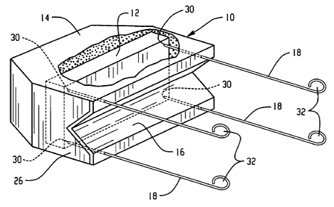
Figure 1 is a drawing showing an example of an anode assembly 10 of the
present invention containing a sacrificial anode or anodes 12 surrounded by an
activated mortar 14 designed to keep the sacrificial anode(s)
electrochemically
active. A non-conductive barrier 16 is positioned on one side of the device,
the
barrier being configured at 26 to fit securely against a reinforcing bar
(shown in
Figure 2). Although the barrier 16 shown is V-shaped to conveniently fit
several
sizes of rebar, other cross sections, such as semi-circular for example, will
be
apparent to those skilled in the art. Tie wires 18 are shown that protrude
through
or adjacent to the barrier 16, the wires 18 being attached to the sacrificial
anodes
at 30 by suitable means, such as soldering. The opposite ends of the wires are
provided with loops 32 for the purpose of wrapping securely around a
reinforcing
bar to make an electrical connection.
Figure 2 is a drawing showing a side view of the anode assembly 10 of the
present invention embedded in a reinforced concrete structure 28. The anode
assembly 10 contains a sacrificial anode or anodes (12 shown in outline)
surrounded by an activated mortar 14. The non-conductive barrier 16 is
positioned on one side of the device, the barrier being configured at 26 to
fit
securely against a reinforcing bar 20. Tie wires 18 are shown that protrude
through or adjacent to the barrier 16, the wires 18 being attached at one end
to the
sacrificial anodes 12 at 30 inside the device. The other end of the wires 18
are
provided, for example, with loops 32 for the purpose of wrapping securely
around
a reinforcing bar 20 to make an electrical connection. The tie wires 18 are
shown
not yet wrapped. The device is shown positioned in an excavation 24 in
original
concrete 22. Figure 2 shows how the configuration of the device allows
mounting
onto the reinforcing bar in a way that allows adequate concrete cover over the
device, and also adequate room below the device for minimum excavation of
concrete. Although not shown in the drawing, it is understood that before the
assembly 10 is embedded in fresh concrete, the tie wires 18 are wrapped
tightly
around the reinforcing bar 20. Tools for this purpose are well known in the
art
and are readily available.
CA 02567120 2006-11-17
WO 2005/121760 PCT/US2005/018768
8
The present invention relates broadly to all reinforced concrete structures
with which cathodic protection systems are useful. Generally, the reinforcing
metal in a reinforced concrete structure is carbon steel. However, other
ferrous-
based metals can also be used.
The anode assembly and method of connection of the present invention
relates to galvanic cathodic protection (GCP), that is, cathodic protection
utilizing
anodes consisting of sacrificial metals, such as zinc, aluminum, magnesium, or
alloys thereof. Of these materials, zinc or zinc alloys are preferred for
reasons of
efficiency, longevity, driving potential and cost. Sacrificial metals are
capable of
providing protective current without the use of ancillary power supplies,
since the
reactions that take place during their use are thermodynamically favored.
The sacrificial metal anodes may be of various geometric configurations,
such as flat plate, expanded or perforated sheet, or cast shapes of various
designs.
It is generally beneficial for the anodes to have a high anode surface area,
that is, a
high area of anode-concrete interface. Preferably, the anode surface area
should
be from three to six times the superficial surface area, whereas the anode
surface
area for plain flat sheet is two times the superficial surface area (counting
both
sides of the sheet).
Since sacrificial metal anodes tend to passivate in the alkaline environment
of concrete, it is necessary to provide an activating agent to maintain the
anode in
an electrochemically active and conductive state. The activating agent
proposed
by Page in US Patent 6,022,469 is an alkali, such as lithium hydroxide, to
maintain the pH of the mortar surrounding the anode above about pH 14. In US
Patent Application No. 08/839,292 filed on April 17, 1997 by Bennett, the use
of
deliquescent or hygroscopic chemicals, collectively called "humectants", is
disclosed to maintain a galvanic sprayed zinc anode in an active state and
delivering protective current. Examples of such chemicals are lithium acetate,
zinc bromide, zinc chloride, calcium chloride, potassium chloride, potassium
nitrite, potassium carbonate, potassium phosphate, ammonium nitrate, ammonium
thiocyanate, lithium thiocyanate, lithium nitrate, lithium bromide, and the
like.
Other effective chemicals for this purpose will become obvious to those
skilled in
CA 02567120 2006-11-17
WO 2005/121760 PCT/US2005/018768
9
the art. In US Patent 6,033,553, two of the most effective such chemicals,
namely
lithiurn nitrate and lithium bromide (LiNO3 and LiBr), are disclosed to
enhance
the performance of sprayed zinc anodes. And in US Patent 6,217,742 B 1, issued
April 17, 2001, Bennett discloses the use of LiNO3 and LiBr to enhance the
performance of embedded discrete anodes. It has been found that a mixture of
lithium nitrate and lithium bromide is particularly effective to enhance the
performance of zinc anodes.
The devices presently used in this application are configured as small
blocks, about 2.5 inches (64 mm) in diameter and about 1.25 inch (32 mm)
thick.
Wires protrude on opposite sides of the block for the purpose of making
electrical
attachment to a steel reinforcing bar. Installation of a device with this size
and
shape does not conform well to established specifications for concrete repair.
For
example, Ohio Department of Transportation (ODOT) TS-519 specifications
require a minimum of 1.25 inches (32 mm) of concrete cover over reinforcing
bars, and excavation of concrete to 0.75 inch (19 mm) behind reinforcing bars.
If
the device currently sold is mounted against a reinforcing bar in vertical
configuration, then the top of the device will be exposed if the concrete
cover is
minimum. On the other hand, if the device is mounted against and beneath the
reinforcing bar in horizontal configuration, this will require the installer
to chip
out at least an additional 0.375 inch (10 mm) behind the bar to make room for
the
device, and even then patch concrete will not completely encapsulate the
device
unless even more concrete is removed. This results in considerable additional
installation expense.
Industrial Applicability
The devices of the present invention conform well to typical specifications
for concrete repair, as can be readily understood by reference to Figure 2. If
the
device of the present invention is 1.25 inches (32 mm) deep, the reinforcing
bar is
0.50 inch (13 mm) in diameter, for example, and the concrete cover over the
reinforcing bar is the minimum 1.25 inches (32 mm), then the cover over the
device will be an acceptable 0.875 inch (22 mm). Even if the space beneath the
reinforcing bar is excavated to the minimum 0.75 inch (19 mm), the clearance
CA 02567120 2006-11-17
WO 2005/121760 PCT/US2005/018768
between the device of the present invention and the concrete behind the bar
will
still be 0.375 inch (10 mm). Thus, the devices of the present invention can be
easily installed without additional chipping of concrete, and without risk of
exposure of the device at the surface of the patch material.
5 This invention also discloses a configuration of a device that mounts easily
and securely to reinforcing bars of various sizes. As shown by example in
Figures
1 and 2, one side of the device has a long indentation that is "V" shaped in
cross
section along one side of the device. This shape conforms well to various
diameters of reinforcing bars, and results in a secure and repeatable mount of
the
10 device to the bar. Other cross sections, such as a semicircle or rectangle,
may also
be envisioned.
The present invention also discloses a non-conductive barrier incorporated
into the side of the device adjacent to the reinforcing bar. Such non-
conductive
barrier may be conveniently constructed of plastic, such as polyvinyl chloride
(PVC), polyvinyl dichloride (PVDC), polypropylene, polyethylene, acrylonitrile-
butadiene-styrene (ABS), epoxy, or the like. The non-conductive barrier is in
intimate contact with the reinforcing bar and preferably extends along at
least
about 4 centimeters of the reinforcing bar. The non-conductive barrier
prevents a
large amount of current from "dumping" directly into the reinforcing steel
directly
adjacent to the device. Such dumping is undesirable since it reduces the
amount
of current that flows to reinforcing steel outside the patch, where it is more
critically needed to prevent ongoing corrosion. Dumping of current to adjacent
steel also results in higher total current flow and, thus, needlessly reduces
the
effective lifetime of the anode. Although the thickness of the non-conductive
barrier is not critical, a thickness of about 1/16 inch (1.6 mm) has been
found to
work satisfactorily.
From the above description of the invention, those skilled in the art will
perceive improvements, changes and modifications. Such improvements, changes
and modifications within the skill of the art are intended to be covered by
the
appended claims below.