Language selection

Search

Patent 2567133 Summary

Third-party information liability

Some of the information on this Web page has been provided by external sources. The Government of Canada is not responsible for the accuracy, reliability or currency of the information supplied by external sources. Users wishing to rely upon this information should consult directly with the source of the information. Content provided by external sources is not subject to official languages, privacy and accessibility requirements.

Claims and Abstract availability

Any discrepancies in the text and image of the Claims and Abstract are due to differing posting times. Text of the Claims and Abstract are posted:

  • At the time the application is open to public inspection;
  • At the time of issue of the patent (grant).
(12) Patent: (11) CA 2567133
(54) English Title: VARISTOR WITH THREE PARALLEL CERAMIC LAYER
(54) French Title: VARISTANCE AVEC TROIS COUCHES DE CERAMIQUE PARALLELES
Status: Granted and Issued
Bibliographic Data
(51) International Patent Classification (IPC):
  • H01C 07/10 (2006.01)
  • B32B 18/00 (2006.01)
  • H01C 07/12 (2006.01)
(72) Inventors :
  • LUO, RIH-LANG (Taiwan, Province of China)
(73) Owners :
  • POWERTECH INDUSTRIAL CO., LTD.
(71) Applicants :
  • POWERTECH INDUSTRIAL CO., LTD. (Taiwan, Province of China)
(74) Agent: BULL, HOUSSER & TUPPER LLP
(74) Associate agent:
(45) Issued: 2009-06-30
(22) Filed Date: 2006-11-02
(41) Open to Public Inspection: 2007-05-08
Examination requested: 2006-11-02
Availability of licence: N/A
Dedicated to the Public: N/A
(25) Language of filing: English

Patent Cooperation Treaty (PCT): No

(30) Application Priority Data:
Application No. Country/Territory Date
94139051 (Taiwan, Province of China) 2005-11-08

Abstracts

English Abstract

The present invention discloses a varistor which comprises three parallel ceramic layers. Each of the ceramic layers has two electrodes on both sides thereof. Four leads are properly arranged between and outside surfaces of the ceramic layers to contact with these electrodes. By further providing one or two wires to connect these leads, the three- or single-phase power sources can be protected in a safer manner.


French Abstract

L'invention concerne une varistance comportant trois couches de céramique parallèles. Chacune des couches de céramique comprend deux électrodes de chaque côté. Quatre broches sont disposées correctement entre les surfaces des couches de céramique et à l'extérieur de celles-ci pour faire le contact avec ces électrodes. En prévoyant ensuite un ou deux fils pour brancher ces broches, les réseaux électriques triphasés ou monophasés peuvent être protégés de façon sécuritaire.

Claims

Note: Claims are shown in the official language in which they were submitted.

WHAT IS CLAIMED IS:
1. A varistor, comprising three ceramic layers, six electrodes and a
plurality of leads, wherein:
the three ceramic layers are arranged in parallel and defined as a 1st
varistor, a 2nd varistor and a 3rd varistor in order;
the six electrodes are defined as a 1st electrode and a 2nd electrode
respectively disposed on both sides of the 1st varistor; a 3rd electrode and
a 4th electrode respectively disposed on both sides of the 2nd varistor; and
a 5th electrode and a 6th electrode respectively disposed on both sides of
the 3rd varistor; and
the plurality of leads are defined as a 1st lead with one end connected to
the 1st electrode, a 2nd lead with one end connected to the 2nd electrode
and the 3rd electrode, a 3rd lead with one end connected to the 4th
electrode and the 5th electrode, and a 4th lead with one end connected to
the 6th electrode.
2. The varistor as claimed in claim 1, wherein the ceramic layers are
made of metal oxide powder.
3. The varistor as claimed in claim 1, further comprising a wire for
conducting the 1st lead and the 4th lead.
4. The varistor as claimed in claim 1, further comprising a wire for
conducting the 1st lead and the 3rd lead, and a wire for conducting the 2nd
lead and the 4th lead.
5. A varistor, comprising three ceramic layers, six electrodes and a
plurality of leads, wherein:
the three ceramic layers are arranged in parallel and defined as a 1st
7

varistor, a 2nd varistor and a 3rd varistor in order;
the six electrodes are defined as a 1st electrode and a 2nd electrode
respectively disposed on both sides of the 1st varistor; a 3rd electrode and
a 4th electrode respectively disposed on both sides of the 2nd varistor; and
a 5th electrode and a 6th electrode respectively disposed on both sides of
the 3rd varistor; and
the plurality of leads are defined as a 1st lead with two ends respectively
connected to the 1st and the 6th electrodes, a 2nd lead with one end
connected to the 2nd electrode and the 3rd electrode, and a 3rd lead with
one end connected to the 4th electrode and the 5th electrode.
8

Description

Note: Descriptions are shown in the official language in which they were submitted.


CA 02567133 2006-11-02
VARISTOR WITH THREE PARALLEL CERAMIC LAYER
BACKGROUND OF THE INVENTION
1. Field of the Invention
The present invention relates to a varistor or surge absorber, and more
particularly to a varistor has three parallel ceramic layers for protecting a
single- or three-phase circuit.
2. Related Prior Art
Fig. 1 shows a conventional varistor. The varistor includes a zinc oxide
ceramic 11 with two electrodes 12 on both sides thereof. The electrodes
are normally made from silver and two leads 13 are welded thereon. The
leads 13 are normally tin-coated copper wires. The varistor is further
coated and packaged with epoxy powder for insulation. The zinc oxide
ceramic 11 with grain boundary can protect a circuit from surge by
transforming the electrical energy into heat dissipation. The relationship of
heat generation (H), Cp specified heat coefficient of material, total mass
(m) and temperature gradient (AT) is based on the principle: H = Cp x m x
AT. That is, temperature gradient (AT) will be smaller for a surge-absorber
with larger mass (m) when the same heat is supplied.
On the other hand, resistance of the varistor will decrease with
increasing of the temperature, and thus current leakage increases. If heat
generation is larger than heat dissipation overtime, the zinc oxide ceramic
will worsen or even flame up due to local high heat. Such situation is very
dangerous for users and circumambience and should be avoided.
1

CA 02567133 2008-07-22
FIG. 2 shows three traditional surge absorbers 21, 22, 23 to protect
the L-N-G (Line-Neutral-Ground) power source, in which the varistor 21
operates on the L-N line, the varistor 22 operates on the N-G line and the
varistor 23 operates on the L-G line. Since the three varistors operate
independently, therefore the heat generated during surge has to be diffused
from the respective varistor.
FIG 3 shows the surge absorber disclosed in R.O.C. (Taiwan) Patent
No. 591837, published June 11, 2004 in which the ceramic (e) comprises
four terminals (a)-(d) as shown in (A), or three terminals when the
terminals (b) and (c) are shorted. Though such design may protect the
L-N-G power source, capacitances between the terminals are significantly
increased by 50% after connecting the terminals (b) and (c), as shown in
(B). In other words, the series or parallel association of the ceramic (e)
results in that capacitive reactance decreases by 66% as the capacitance
increases by 50%. If an alternating current is supplied, current leakage will
increase and the device will be damaged. The tests regarding this device
also indicate that the electrodes thereof do not operate independently.
To solve the above problem, the present invention thus provides an
improved varistor.
SUMMARY OF THE INVENTION
One object of the present invention is to provide a varistor (or surge
absorber), which can independently protect individual circuit lines of a
three-phase power source.
Another object of the present invention is to provide a varistor, which
can integrally protect the lines of a single-phase power source.
2

CA 02567133 2006-11-02
A further object of the present invention is to provide a varistor, which
has a normally functional breakdown voltage and operates at a lower
temperature.
The varistor of the present invention comprises three parallel ceramic
layers each having two electrodes disposed on both sides, and a plurality
of leads properly connecting these electrodes to form a three- or
single-phase varistor.
BRIEF DESCRIPTION OF THE DRAWINGS
Fig. 1 shows a conventional varistor.
FIG 2 shows three traditional surge absorbers to protect the L-N-G
power source.
FIG 3 shows the surge absorber disclosed in an R.O.C. Patent.
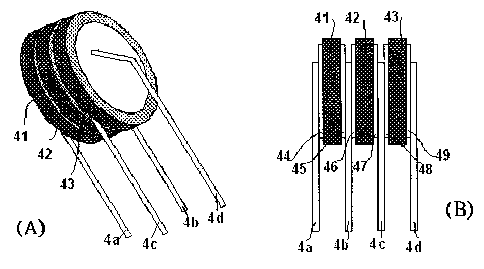
FIG 4 illustrates the perspective and cross-section views of the
varistor in accordance with the present invention.
FIG. 5 illustrates the connection of the leads and an equivalent circuit
for protecting a three-phase power source.
FIG 6 illustrates the connection of the leads and an equivalent circuit
for protecting a single-phase power source.
DETAILED DESCRIPTION OF THE PREFERRED
EMBODIMENTS
To describe the present invention in detail, the preferred embodiments
are illustrated with the drawings.
In FIG. 4, (A) and (B) are respectively a perspective view and a
3

CA 02567133 2006-11-02
cross-section view of a varistor in accordance with the present invention.
The varistor is composed of three ceramic layers, six electrodes and four
leads.
The three ceramic layers are integrated in parallel and sequentially
defined as the 1 st varistor 41, the 2nd varistor 42, and the 3rd varistor 43.
Each of the ceramic layers 41 -43 can provide an independent path for
surge as the conventional varistor. The ceramic layers are preferably made
of metal oxide powder, for example, zinc oxide. The ceramic layers can be
shaped as desired, for example, disk-shaped, square, spherical, etc. The
ceramic layers can be combined in any proper ways, for example,
contacting each other with an adhesion, or formed integrally.
Among the six electrodes, the 1 st electrode 44 and the 2nd electrode 45
are respectively disposed on two opposite surfaces of the lst varistor 41;
the 3rd electrode 46 and the 4th electrode 47 are respectively disposed on
two opposite surfaces of the 2nd varistor 42; and the 5th electrode 48 and
the 6th electrode 49 are respectively disposed on two opposite surfaces of
the 3rd varistor 43. Relatively, the 3rd electrode 46 is adjacent to the 2nd
electrode 45; and the 5th electrode 48 is adjacent to the 4th electrode 47.
The four leads are defined as the 1 st lead 4a welded to the 1 st electrode
44, the 2nd lead 4b welded to the 2nd electrode 45 and the 3rd electrode
46, the 3rd lead 4c welded to the 4th electrode 47 and the 5th electrode 48,
and the 4th lead 4d welded to the 6th electrode 49.
In FIG 5, (A) and (B) respectively illustrate connection of the leads and
an equivalent circuit for protecting a three-phase power source, in which
the leads 4a and 4d are connected with a wire 51. Therefore, the varistor
4

CA 02567133 2006-11-02
41 may protect the L-N circuit, the varistor 42 may protect the N-G circuit,
and the varistor 43 may protect the L-G circuit. Though each varistor
operates independently, heat generated by one varistor can be transferred
to the others. In other words, the varistor can remain a lower temperature
during surge since a larger mass and a wider surface area are provided for
heat generation and transfer.
In FIG 6, (A) and (B) respectively illustrate connection of the leads and
an equivalent circuit for protecting a single-phase power source, in which
the leads 4a and 4c are connected with a wire 61, and the leads 4b and 4d
are connected with a wire 62. As a result, the ceramic layers 41, 42, 43
may together protect the circuit between L 1 and L2. Since the three
ceramic layers operate as a whole, protection effect for surge is promoted,
and the temperature is also remained lower.
In accordance with the structure of the present invention, methods for
producing the varistor are not restricted, but able to properly arrange and
combine the ceramic layers, electrodes and leads. Furthermore, the
ceramic layers, electrodes and leads can be arranged in different orders or
positions optionally.
As described in the above, the varistor of the present invention performs
advantages as follows:
l. The varistor of the present invention provides a larger mass and
surface area for heat absorption and dissipation and is obviously safer and
more durable than the conventional.
2. The three parallel ceramic layers of the varistor can independently
operate on respective circuit lines of a three-phase power source.
5

CA 02567133 2006-11-02
3. The three parallel ceramic layers of the varistor can integrally
operate on the circuit lines of a single-phase power source.
4. Rated working voltage for the individual circuit lines can be
adjusted optionally, for example, a higher breakdown voltage for
grounding.
5. The varistor needs less leads than the conventional composed of
three independent ceramic layers and six leads, and therefore the cost is
reduced.
6. The varistor of the present invention provides a larger mass and
surface area for heat generation and dissipation, and thus less extra
elements, for example, thermal cut-off (TCO) fuses, are necessary than the
conventional.
In the above preferred embodiment, the leads 4a, 4b, 4c and 4d can be
separated and properly connected to the electrodes by associating with
additional wires. Alternatively, these leads 4a, 4b, 4c and 4d can be
considered as portions of one or more leads; that is, the associated leads
and wire are made a whole depending on customer's requirements or
manufacturing processes.
6

Representative Drawing
A single figure which represents the drawing illustrating the invention.
Administrative Status

2024-08-01:As part of the Next Generation Patents (NGP) transition, the Canadian Patents Database (CPD) now contains a more detailed Event History, which replicates the Event Log of our new back-office solution.

Please note that "Inactive:" events refers to events no longer in use in our new back-office solution.

For a clearer understanding of the status of the application/patent presented on this page, the site Disclaimer , as well as the definitions for Patent , Event History , Maintenance Fee  and Payment History  should be consulted.

Event History

Description Date
Inactive: Recording certificate (Transfer) 2022-02-23
Change of Address or Method of Correspondence Request Received 2022-02-03
Inactive: Single transfer 2022-02-03
Common Representative Appointed 2019-10-30
Grant by Issuance 2009-06-30
Inactive: Cover page published 2009-06-29
Inactive: Final fee received 2009-04-15
Pre-grant 2009-04-15
Letter Sent 2009-03-19
Notice of Allowance is Issued 2009-03-19
Inactive: Approved for allowance (AFA) 2009-03-11
Amendment Received - Voluntary Amendment 2008-07-22
Inactive: S.30(2) Rules - Examiner requisition 2008-01-30
Inactive: S.29 Rules - Examiner requisition 2008-01-30
Application Published (Open to Public Inspection) 2007-05-08
Inactive: Cover page published 2007-05-07
Letter Sent 2007-03-21
Inactive: Single transfer 2007-02-16
Inactive: IPC assigned 2007-01-12
Inactive: First IPC assigned 2007-01-12
Inactive: IPC assigned 2007-01-12
Inactive: IPC assigned 2006-12-31
Inactive: Courtesy letter - Evidence 2006-12-12
Inactive: Filing certificate - RFE (English) 2006-12-08
Letter Sent 2006-12-08
Application Received - Regular National 2006-12-08
Request for Examination Requirements Determined Compliant 2006-11-02
All Requirements for Examination Determined Compliant 2006-11-02

Abandonment History

There is no abandonment history.

Maintenance Fee

The last payment was received on 2008-10-22

Note : If the full payment has not been received on or before the date indicated, a further fee may be required which may be one of the following

  • the reinstatement fee;
  • the late payment fee; or
  • additional fee to reverse deemed expiry.

Patent fees are adjusted on the 1st of January every year. The amounts above are the current amounts if received by December 31 of the current year.
Please refer to the CIPO Patent Fees web page to see all current fee amounts.

Owners on Record

Note: Records showing the ownership history in alphabetical order.

Current Owners on Record
POWERTECH INDUSTRIAL CO., LTD.
Past Owners on Record
RIH-LANG LUO
Past Owners that do not appear in the "Owners on Record" listing will appear in other documentation within the application.
Documents

To view selected files, please enter reCAPTCHA code :


To view images, click a link in the Document Description column (Temporarily unavailable). To download the documents, select one or more checkboxes in the first column and then click the "Download Selected in PDF format (Zip Archive)" or the "Download Selected as Single PDF" button.

List of published and non-published patent-specific documents on the CPD .

If you have any difficulty accessing content, you can call the Client Service Centre at 1-866-997-1936 or send them an e-mail at CIPO Client Service Centre.

({010=All Documents, 020=As Filed, 030=As Open to Public Inspection, 040=At Issuance, 050=Examination, 060=Incoming Correspondence, 070=Miscellaneous, 080=Outgoing Correspondence, 090=Payment})


Document
Description 
Date
(yyyy-mm-dd) 
Number of pages   Size of Image (KB) 
Description 2006-11-01 6 230
Abstract 2006-11-01 1 12
Claims 2006-11-01 2 77
Drawings 2006-11-01 2 98
Representative drawing 2007-04-23 1 34
Description 2008-07-21 6 229
Drawings 2008-07-21 2 91
Claims 2008-07-21 2 52
Representative drawing 2009-03-15 1 33
Acknowledgement of Request for Examination 2006-12-07 1 178
Filing Certificate (English) 2006-12-07 1 158
Courtesy - Certificate of registration (related document(s)) 2007-03-20 1 105
Reminder of maintenance fee due 2008-07-02 1 113
Commissioner's Notice - Application Found Allowable 2009-03-18 1 163
Notice: Maintenance Fee Reminder 2014-08-04 1 120
Notice: Maintenance Fee Reminder 2015-08-03 1 119
Notice: Maintenance Fee Reminder 2016-08-02 1 120
Notice: Maintenance Fee Reminder 2017-08-02 1 119
Notice: Maintenance Fee Reminder 2018-08-05 1 120
Notice: Maintenance Fee Reminder 2019-08-05 1 120
Courtesy - Certificate of Recordal (Transfer) 2022-02-22 1 402
Fees 2011-10-11 1 155
Maintenance fee payment 2018-10-28 1 24
Correspondence 2006-12-07 1 27
Fees 2008-10-21 1 36
Correspondence 2009-04-14 1 38
Fees 2009-10-29 1 201
Fees 2010-10-07 1 201
Fees 2016-10-12 1 24
Maintenance fee payment 2017-10-01 1 24
Maintenance fee payment 2020-10-26 1 25
Change to the Method of Correspondence 2022-02-02 3 68