Sélection de la langue

Search

Sommaire du brevet 2567133 

Énoncé de désistement de responsabilité concernant l'information provenant de tiers

Une partie des informations de ce site Web a été fournie par des sources externes. Le gouvernement du Canada n'assume aucune responsabilité concernant la précision, l'actualité ou la fiabilité des informations fournies par les sources externes. Les utilisateurs qui désirent employer cette information devraient consulter directement la source des informations. Le contenu fourni par les sources externes n'est pas assujetti aux exigences sur les langues officielles, la protection des renseignements personnels et l'accessibilité.

Disponibilité de l'Abrégé et des Revendications

L'apparition de différences dans le texte et l'image des Revendications et de l'Abrégé dépend du moment auquel le document est publié. Les textes des Revendications et de l'Abrégé sont affichés :

  • lorsque la demande peut être examinée par le public;
  • lorsque le brevet est émis (délivrance).
(12) Brevet: (11) CA 2567133
(54) Titre français: VARISTANCE AVEC TROIS COUCHES DE CERAMIQUE PARALLELES
(54) Titre anglais: VARISTOR WITH THREE PARALLEL CERAMIC LAYER
Statut: Accordé et délivré
Données bibliographiques
(51) Classification internationale des brevets (CIB):
  • H01C 07/10 (2006.01)
  • B32B 18/00 (2006.01)
  • H01C 07/12 (2006.01)
(72) Inventeurs :
  • LUO, RIH-LANG (Taïwan, Province de Chine)
(73) Titulaires :
  • POWERTECH INDUSTRIAL CO., LTD.
(71) Demandeurs :
  • POWERTECH INDUSTRIAL CO., LTD. (Taïwan, Province de Chine)
(74) Agent: BULL, HOUSSER & TUPPER LLP
(74) Co-agent:
(45) Délivré: 2009-06-30
(22) Date de dépôt: 2006-11-02
(41) Mise à la disponibilité du public: 2007-05-08
Requête d'examen: 2006-11-02
Licence disponible: S.O.
Cédé au domaine public: S.O.
(25) Langue des documents déposés: Anglais

Traité de coopération en matière de brevets (PCT): Non

(30) Données de priorité de la demande:
Numéro de la demande Pays / territoire Date
94139051 (Taïwan, Province de Chine) 2005-11-08

Abrégés

Abrégé français

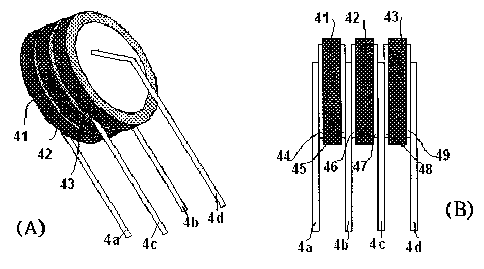
L'invention concerne une varistance comportant trois couches de céramique parallèles. Chacune des couches de céramique comprend deux électrodes de chaque côté. Quatre broches sont disposées correctement entre les surfaces des couches de céramique et à l'extérieur de celles-ci pour faire le contact avec ces électrodes. En prévoyant ensuite un ou deux fils pour brancher ces broches, les réseaux électriques triphasés ou monophasés peuvent être protégés de façon sécuritaire.


Abrégé anglais

The present invention discloses a varistor which comprises three parallel ceramic layers. Each of the ceramic layers has two electrodes on both sides thereof. Four leads are properly arranged between and outside surfaces of the ceramic layers to contact with these electrodes. By further providing one or two wires to connect these leads, the three- or single-phase power sources can be protected in a safer manner.

Revendications

Note : Les revendications sont présentées dans la langue officielle dans laquelle elles ont été soumises.


WHAT IS CLAIMED IS:
1. A varistor, comprising three ceramic layers, six electrodes and a
plurality of leads, wherein:
the three ceramic layers are arranged in parallel and defined as a 1st
varistor, a 2nd varistor and a 3rd varistor in order;
the six electrodes are defined as a 1st electrode and a 2nd electrode
respectively disposed on both sides of the 1st varistor; a 3rd electrode and
a 4th electrode respectively disposed on both sides of the 2nd varistor; and
a 5th electrode and a 6th electrode respectively disposed on both sides of
the 3rd varistor; and
the plurality of leads are defined as a 1st lead with one end connected to
the 1st electrode, a 2nd lead with one end connected to the 2nd electrode
and the 3rd electrode, a 3rd lead with one end connected to the 4th
electrode and the 5th electrode, and a 4th lead with one end connected to
the 6th electrode.
2. The varistor as claimed in claim 1, wherein the ceramic layers are
made of metal oxide powder.
3. The varistor as claimed in claim 1, further comprising a wire for
conducting the 1st lead and the 4th lead.
4. The varistor as claimed in claim 1, further comprising a wire for
conducting the 1st lead and the 3rd lead, and a wire for conducting the 2nd
lead and the 4th lead.
5. A varistor, comprising three ceramic layers, six electrodes and a
plurality of leads, wherein:
the three ceramic layers are arranged in parallel and defined as a 1st
7

varistor, a 2nd varistor and a 3rd varistor in order;
the six electrodes are defined as a 1st electrode and a 2nd electrode
respectively disposed on both sides of the 1st varistor; a 3rd electrode and
a 4th electrode respectively disposed on both sides of the 2nd varistor; and
a 5th electrode and a 6th electrode respectively disposed on both sides of
the 3rd varistor; and
the plurality of leads are defined as a 1st lead with two ends respectively
connected to the 1st and the 6th electrodes, a 2nd lead with one end
connected to the 2nd electrode and the 3rd electrode, and a 3rd lead with
one end connected to the 4th electrode and the 5th electrode.
8

Description

Note : Les descriptions sont présentées dans la langue officielle dans laquelle elles ont été soumises.


CA 02567133 2006-11-02
VARISTOR WITH THREE PARALLEL CERAMIC LAYER
BACKGROUND OF THE INVENTION
1. Field of the Invention
The present invention relates to a varistor or surge absorber, and more
particularly to a varistor has three parallel ceramic layers for protecting a
single- or three-phase circuit.
2. Related Prior Art
Fig. 1 shows a conventional varistor. The varistor includes a zinc oxide
ceramic 11 with two electrodes 12 on both sides thereof. The electrodes
are normally made from silver and two leads 13 are welded thereon. The
leads 13 are normally tin-coated copper wires. The varistor is further
coated and packaged with epoxy powder for insulation. The zinc oxide
ceramic 11 with grain boundary can protect a circuit from surge by
transforming the electrical energy into heat dissipation. The relationship of
heat generation (H), Cp specified heat coefficient of material, total mass
(m) and temperature gradient (AT) is based on the principle: H = Cp x m x
AT. That is, temperature gradient (AT) will be smaller for a surge-absorber
with larger mass (m) when the same heat is supplied.
On the other hand, resistance of the varistor will decrease with
increasing of the temperature, and thus current leakage increases. If heat
generation is larger than heat dissipation overtime, the zinc oxide ceramic
will worsen or even flame up due to local high heat. Such situation is very
dangerous for users and circumambience and should be avoided.
1

CA 02567133 2008-07-22
FIG. 2 shows three traditional surge absorbers 21, 22, 23 to protect
the L-N-G (Line-Neutral-Ground) power source, in which the varistor 21
operates on the L-N line, the varistor 22 operates on the N-G line and the
varistor 23 operates on the L-G line. Since the three varistors operate
independently, therefore the heat generated during surge has to be diffused
from the respective varistor.
FIG 3 shows the surge absorber disclosed in R.O.C. (Taiwan) Patent
No. 591837, published June 11, 2004 in which the ceramic (e) comprises
four terminals (a)-(d) as shown in (A), or three terminals when the
terminals (b) and (c) are shorted. Though such design may protect the
L-N-G power source, capacitances between the terminals are significantly
increased by 50% after connecting the terminals (b) and (c), as shown in
(B). In other words, the series or parallel association of the ceramic (e)
results in that capacitive reactance decreases by 66% as the capacitance
increases by 50%. If an alternating current is supplied, current leakage will
increase and the device will be damaged. The tests regarding this device
also indicate that the electrodes thereof do not operate independently.
To solve the above problem, the present invention thus provides an
improved varistor.
SUMMARY OF THE INVENTION
One object of the present invention is to provide a varistor (or surge
absorber), which can independently protect individual circuit lines of a
three-phase power source.
Another object of the present invention is to provide a varistor, which
can integrally protect the lines of a single-phase power source.
2

CA 02567133 2006-11-02
A further object of the present invention is to provide a varistor, which
has a normally functional breakdown voltage and operates at a lower
temperature.
The varistor of the present invention comprises three parallel ceramic
layers each having two electrodes disposed on both sides, and a plurality
of leads properly connecting these electrodes to form a three- or
single-phase varistor.
BRIEF DESCRIPTION OF THE DRAWINGS
Fig. 1 shows a conventional varistor.
FIG 2 shows three traditional surge absorbers to protect the L-N-G
power source.
FIG 3 shows the surge absorber disclosed in an R.O.C. Patent.
FIG 4 illustrates the perspective and cross-section views of the
varistor in accordance with the present invention.
FIG. 5 illustrates the connection of the leads and an equivalent circuit
for protecting a three-phase power source.
FIG 6 illustrates the connection of the leads and an equivalent circuit
for protecting a single-phase power source.
DETAILED DESCRIPTION OF THE PREFERRED
EMBODIMENTS
To describe the present invention in detail, the preferred embodiments
are illustrated with the drawings.
In FIG. 4, (A) and (B) are respectively a perspective view and a
3

CA 02567133 2006-11-02
cross-section view of a varistor in accordance with the present invention.
The varistor is composed of three ceramic layers, six electrodes and four
leads.
The three ceramic layers are integrated in parallel and sequentially
defined as the 1 st varistor 41, the 2nd varistor 42, and the 3rd varistor 43.
Each of the ceramic layers 41 -43 can provide an independent path for
surge as the conventional varistor. The ceramic layers are preferably made
of metal oxide powder, for example, zinc oxide. The ceramic layers can be
shaped as desired, for example, disk-shaped, square, spherical, etc. The
ceramic layers can be combined in any proper ways, for example,
contacting each other with an adhesion, or formed integrally.
Among the six electrodes, the 1 st electrode 44 and the 2nd electrode 45
are respectively disposed on two opposite surfaces of the lst varistor 41;
the 3rd electrode 46 and the 4th electrode 47 are respectively disposed on
two opposite surfaces of the 2nd varistor 42; and the 5th electrode 48 and
the 6th electrode 49 are respectively disposed on two opposite surfaces of
the 3rd varistor 43. Relatively, the 3rd electrode 46 is adjacent to the 2nd
electrode 45; and the 5th electrode 48 is adjacent to the 4th electrode 47.
The four leads are defined as the 1 st lead 4a welded to the 1 st electrode
44, the 2nd lead 4b welded to the 2nd electrode 45 and the 3rd electrode
46, the 3rd lead 4c welded to the 4th electrode 47 and the 5th electrode 48,
and the 4th lead 4d welded to the 6th electrode 49.
In FIG 5, (A) and (B) respectively illustrate connection of the leads and
an equivalent circuit for protecting a three-phase power source, in which
the leads 4a and 4d are connected with a wire 51. Therefore, the varistor
4

CA 02567133 2006-11-02
41 may protect the L-N circuit, the varistor 42 may protect the N-G circuit,
and the varistor 43 may protect the L-G circuit. Though each varistor
operates independently, heat generated by one varistor can be transferred
to the others. In other words, the varistor can remain a lower temperature
during surge since a larger mass and a wider surface area are provided for
heat generation and transfer.
In FIG 6, (A) and (B) respectively illustrate connection of the leads and
an equivalent circuit for protecting a single-phase power source, in which
the leads 4a and 4c are connected with a wire 61, and the leads 4b and 4d
are connected with a wire 62. As a result, the ceramic layers 41, 42, 43
may together protect the circuit between L 1 and L2. Since the three
ceramic layers operate as a whole, protection effect for surge is promoted,
and the temperature is also remained lower.
In accordance with the structure of the present invention, methods for
producing the varistor are not restricted, but able to properly arrange and
combine the ceramic layers, electrodes and leads. Furthermore, the
ceramic layers, electrodes and leads can be arranged in different orders or
positions optionally.
As described in the above, the varistor of the present invention performs
advantages as follows:
l. The varistor of the present invention provides a larger mass and
surface area for heat absorption and dissipation and is obviously safer and
more durable than the conventional.
2. The three parallel ceramic layers of the varistor can independently
operate on respective circuit lines of a three-phase power source.
5

CA 02567133 2006-11-02
3. The three parallel ceramic layers of the varistor can integrally
operate on the circuit lines of a single-phase power source.
4. Rated working voltage for the individual circuit lines can be
adjusted optionally, for example, a higher breakdown voltage for
grounding.
5. The varistor needs less leads than the conventional composed of
three independent ceramic layers and six leads, and therefore the cost is
reduced.
6. The varistor of the present invention provides a larger mass and
surface area for heat generation and dissipation, and thus less extra
elements, for example, thermal cut-off (TCO) fuses, are necessary than the
conventional.
In the above preferred embodiment, the leads 4a, 4b, 4c and 4d can be
separated and properly connected to the electrodes by associating with
additional wires. Alternatively, these leads 4a, 4b, 4c and 4d can be
considered as portions of one or more leads; that is, the associated leads
and wire are made a whole depending on customer's requirements or
manufacturing processes.
6

Dessin représentatif
Une figure unique qui représente un dessin illustrant l'invention.
États administratifs

2024-08-01 : Dans le cadre de la transition vers les Brevets de nouvelle génération (BNG), la base de données sur les brevets canadiens (BDBC) contient désormais un Historique d'événement plus détaillé, qui reproduit le Journal des événements de notre nouvelle solution interne.

Veuillez noter que les événements débutant par « Inactive : » se réfèrent à des événements qui ne sont plus utilisés dans notre nouvelle solution interne.

Pour une meilleure compréhension de l'état de la demande ou brevet qui figure sur cette page, la rubrique Mise en garde , et les descriptions de Brevet , Historique d'événement , Taxes périodiques et Historique des paiements devraient être consultées.

Historique d'événement

Description Date
Inactive : Certificat d'inscription (Transfert) 2022-02-23
Requête pour le changement d'adresse ou de mode de correspondance reçue 2022-02-03
Inactive : Transfert individuel 2022-02-03
Représentant commun nommé 2019-10-30
Accordé par délivrance 2009-06-30
Inactive : Page couverture publiée 2009-06-29
Inactive : Taxe finale reçue 2009-04-15
Préoctroi 2009-04-15
Lettre envoyée 2009-03-19
Un avis d'acceptation est envoyé 2009-03-19
Inactive : Approuvée aux fins d'acceptation (AFA) 2009-03-11
Modification reçue - modification volontaire 2008-07-22
Inactive : Dem. de l'examinateur par.30(2) Règles 2008-01-30
Inactive : Dem. de l'examinateur art.29 Règles 2008-01-30
Demande publiée (accessible au public) 2007-05-08
Inactive : Page couverture publiée 2007-05-07
Lettre envoyée 2007-03-21
Inactive : Transfert individuel 2007-02-16
Inactive : CIB attribuée 2007-01-12
Inactive : CIB en 1re position 2007-01-12
Inactive : CIB attribuée 2007-01-12
Inactive : CIB attribuée 2006-12-31
Inactive : Lettre de courtoisie - Preuve 2006-12-12
Inactive : Certificat de dépôt - RE (Anglais) 2006-12-08
Lettre envoyée 2006-12-08
Demande reçue - nationale ordinaire 2006-12-08
Exigences pour une requête d'examen - jugée conforme 2006-11-02
Toutes les exigences pour l'examen - jugée conforme 2006-11-02

Historique d'abandonnement

Il n'y a pas d'historique d'abandonnement

Taxes périodiques

Le dernier paiement a été reçu le 2008-10-22

Avis : Si le paiement en totalité n'a pas été reçu au plus tard à la date indiquée, une taxe supplémentaire peut être imposée, soit une des taxes suivantes :

  • taxe de rétablissement ;
  • taxe pour paiement en souffrance ; ou
  • taxe additionnelle pour le renversement d'une péremption réputée.

Les taxes sur les brevets sont ajustées au 1er janvier de chaque année. Les montants ci-dessus sont les montants actuels s'ils sont reçus au plus tard le 31 décembre de l'année en cours.
Veuillez vous référer à la page web des taxes sur les brevets de l'OPIC pour voir tous les montants actuels des taxes.

Titulaires au dossier

Les titulaires actuels et antérieures au dossier sont affichés en ordre alphabétique.

Titulaires actuels au dossier
POWERTECH INDUSTRIAL CO., LTD.
Titulaires antérieures au dossier
RIH-LANG LUO
Les propriétaires antérieurs qui ne figurent pas dans la liste des « Propriétaires au dossier » apparaîtront dans d'autres documents au dossier.
Documents

Pour visionner les fichiers sélectionnés, entrer le code reCAPTCHA :


Pour visualiser une image, cliquer sur un lien dans la colonne description du document (Temporairement non-disponible). Pour télécharger l'image (les images), cliquer l'une ou plusieurs cases à cocher dans la première colonne et ensuite cliquer sur le bouton "Télécharger sélection en format PDF (archive Zip)" ou le bouton "Télécharger sélection (en un fichier PDF fusionné)".

Liste des documents de brevet publiés et non publiés sur la BDBC .

Si vous avez des difficultés à accéder au contenu, veuillez communiquer avec le Centre de services à la clientèle au 1-866-997-1936, ou envoyer un courriel au Centre de service à la clientèle de l'OPIC.

({010=Tous les documents, 020=Au moment du dépôt, 030=Au moment de la mise à la disponibilité du public, 040=À la délivrance, 050=Examen, 060=Correspondance reçue, 070=Divers, 080=Correspondance envoyée, 090=Paiement})


Description du
Document 
Date
(aaaa-mm-jj) 
Nombre de pages   Taille de l'image (Ko) 
Description 2006-11-01 6 230
Abrégé 2006-11-01 1 12
Revendications 2006-11-01 2 77
Dessins 2006-11-01 2 98
Dessin représentatif 2007-04-23 1 34
Description 2008-07-21 6 229
Dessins 2008-07-21 2 91
Revendications 2008-07-21 2 52
Dessin représentatif 2009-03-15 1 33
Accusé de réception de la requête d'examen 2006-12-07 1 178
Certificat de dépôt (anglais) 2006-12-07 1 158
Courtoisie - Certificat d'enregistrement (document(s) connexe(s)) 2007-03-20 1 105
Rappel de taxe de maintien due 2008-07-02 1 113
Avis du commissaire - Demande jugée acceptable 2009-03-18 1 163
Avis de rappel: Taxes de maintien 2014-08-04 1 120
Avis de rappel: Taxes de maintien 2015-08-03 1 119
Avis de rappel: Taxes de maintien 2016-08-02 1 120
Avis de rappel: Taxes de maintien 2017-08-02 1 119
Avis de rappel: Taxes de maintien 2018-08-05 1 120
Avis de rappel: Taxes de maintien 2019-08-05 1 120
Courtoisie - Certificat d'inscription (transfert) 2022-02-22 1 402
Taxes 2011-10-11 1 155
Paiement de taxe périodique 2018-10-28 1 24
Correspondance 2006-12-07 1 27
Taxes 2008-10-21 1 36
Correspondance 2009-04-14 1 38
Taxes 2009-10-29 1 201
Taxes 2010-10-07 1 201
Taxes 2016-10-12 1 24
Paiement de taxe périodique 2017-10-01 1 24
Paiement de taxe périodique 2020-10-26 1 25
Changement à la méthode de correspondance 2022-02-02 3 68