Note: Descriptions are shown in the official language in which they were submitted.
CA 02567168 2006-11-17
WO 2005/113721 PCT/US2005/017695
-1-
PROCESS AND APPARATUS FOR REMOVING
COKE FORMED DURING STEAM CRACKING OF
HYDROCARBON FEEDSTOCKS CONTAINING RESIDS
FIELD OF THE INVENTION
[0001] The present invention relates to the cracking of hydrocarbons that
contain relatively non-volatile hydrocarbons and other contaminants. More
particularly, the present invention relates to reducing coking in apparatus
used for
cracking hydrocarbons.
BACKGROUND OF THE INVENTION
[0002] Steam cracking, also referred to as pyrolysis, has long been used to
crack various hydrocarbon feedstocks into olefins, preferably light olefins
such as
ethylene, propylene, and butenes. Conventional steam cracking utilizes a
pyrolysis furnace which has two main sections: a convection section and a
radiant
section. The hydrocarbon feedstock typically enters the convection section of
the
furnace as a liquid (except for light feedstocks which enter as a vapor)
wherein it
is typically heated and vaporized by indirect contact with hot flue gas from
the
radiant section and by direct contact with steam. The vaporized feedstock and
steam mixture is then introduced into the radiant section where the cracking
takes
place. The resulting products including olefins leave the pyrolysis furnace
for
further downstream processing, including quenching.
[0003] Pyrolysis involves heating the feedstock sufficiently to cause
thermal decomposition of the larger molecules. The pyrolysis process, however,
produces molecules which tend to combine to form high molecular weight
materials known as tar. Tar is a high-boiling point, viscous, reactive
material that
can foul equipment under certain conditions. In general, feedstocks containing
higher boiling materials tend to produce greater quantities of tar.
[0004] The formation of tar after the pyrolysis effluent leaves the steam
cracking furnace can be minimized by rapidly reducing the temperature of the
CA 02567168 2006-11-17
WO 2005/113721 PCT/US2005/017695
-2-
effluent exiting the pyrolysis unit to a level at which the tar-forming
reactions are
greatly slowed. This cooling which may be achieved in one or more steps and
using one or more methods is referred to as quenching.
[0005] Conventional steam cracking systems have been effective for
cracking high-quality feedstock which contain a large fraction of light
volatile
hydrocarbons, such as gas oil and naphtha. However, steam cracking economics
sometimes favor cracking lower cost heavy feedstocks such as, by way of non-
limiting examples, crude oil and atmospheric residue. Crude oil and
atmospheric
residue often contain high molecular weight, non-volatile components with
boiling points in excess of 1100 F (590 C) otherwise known as resids. The non-
volatile components of these feedstocks lay down as coke in the convection
section of conventional pyrolysis furnaces. Only very low levels of non-
volatile
components can be tolerated in the convection section downstream of the point
where the lighter components have fully vaporized.
[0006] In most commercial naphtha and gas oil crackers, cooling of the
effluent from the cracking furnace is normally achieved using a system of
transfer
line heat exchangers, a primary fractionator, and a water quench tower or
indirect
condenser. The steam generated in transfer line exchangers can be used to
drive
large steam turbines which power the major compressors used elsewhere in the
ethylene production unit. To obtain high energy-efficiency and power
production
in the steam turbines, it is necessary to superheat the steam produced in the
transfer line exchangers.
[0007] Cracking heavier feeds, such as kerosenes and gas oils, produces
large amounts of tar, which lead to rapid coking in the radiant section of the
furnace as well as fouling in the transfer line exchangers preferred in
lighter liquid
cracking service.
[0008] Additionally, during transport some naphthas are contaminated
with heavy crude oil containing non-volatile components. Conventional
pyrolysis
furnaces do not have the flexibility to process residues, crudes, or many
residue-
CA 02567168 2009-12-16
-3-
or crude-contaminated gas oils or naphthas which are contaminated with non-
volatile
components.
[0009] To address coking problems, U.S. Patent 3,617,493 discloses the use of
an external vaporization drum for the crude oil feed and discloses the use of
a first
flash to remove naphtha as vapor and a second flash to remove vapors with a
boiling
point between 450 and 1100 F (230 and 590 C). The vapors are cracked in the
pyrolysis furnace into olefins and the separated liquids from the two flash
tanks are
removed, stripped with steam, and used as fuel.
[0010] U.S. Patent 3,718,709 discloses a process to minimize coke deposition.
It describes preheating of heavy feedstock inside or outside a pyrolysis
furnace to
vaporize about 50% of the heavy feedstock with superheated steam and the
removal
of the residual, separated liquid. The vaporized hydrocarbons, which contain
mostly
light volatile hydrocarbons, are subjected to cracking. Periodic regeneration
above
pyrolysis temperature is effected with air and steam.
[0011] U.S. Patent 5,190,634 discloses a process for inhibiting coke formation
in a furnace by preheating the feedstock in the presence of a small, critical
amount of
hydrogen in the convection section. The presence of hydrogen in the convection
section inhibits the polymerization reaction of the hydrocarbons thereby
inhibiting
coke formation.
[0012] U.S. Patent 5,580,443 discloses a process wherein the feedstock is
first
preheated and then withdrawn from a preheater in the convection section of the
pyrolysis furnace. This preheated feedstock is then mixed with a predetermined
amount of steam (the dilution steam) and is then introduced into a gas-liquid
separator
to separate and remove a required proportion of the non-volatiles as liquid
from the
separator. The separated vapor from the gas-liquid separator is returned to
the
pyrolysis furnace for heating and cracking.
CA 02567168 2009-12-16
t'. r
-4-
[0013] U.S. Patent Publication US 2004/0004022 Al, published January 8,
2004, which is incorporated herein by reference, describes an advantageously
controlled process to optimize the cracking of volatile hydrocarbons contained
in
the heavy hydrocarbon feedstocks and to reduce and avoid coking problems. It
provides a method to maintain a relatively constant ratio of vapor to liquid
leaving
the flash by maintaining a relatively constant temperature of the stream
entering
the flash. More specifically, the constant temperature of the flash stream is
maintained by automatically adjusting the amount of a fluid stream mixed with
the
heavy hydrocarbon feedstock prior to the flash. The fluid can be water.
[0014] WO 2005/095548 describes a process for cracking
heavy hydrocarbon feedstock which mixes heavy hydrocarbon feedstock with a
fluid, e.g., hydrocarbon or water, to form a mixture stream which is flashed
to
form a vapor phase and a liquid phase, the vapor phase being subsequently
cracked to provide olefins, and the product effluent cooled in a transfer line
exchanger, wherein the amount of fluid mixed with the feedstock is varied in
accordance with a selected operating parameter of the process, e.g.,
temperature of
the mixture stream before the mixture stream is flashed.
100151 In using a flash to separate heavy liquid hydrocarbon fractions from
the lighter fractions which can be processed in the pyrolysis furnace, it is
important to effect the separation so that most of the non-volatile components
will
be in the liquid phase. Otherwise, heavy, coke-forming non-volatile components
in the vapor are carried into the furnace causing coking problems. However,
the
flashing in a flash/separation vessel is typically accompanied by coking of
internal *
surfaces in and proximally downstream of the vessel. The extent of such coking
is
dependent upon various factors including feed type, preheating protocol, and
design of the vessel. Liquids contacting the internal surfaces of the vessel
and
downstream equipment provide coatings of films that are precursors to coke.
CA 02567168 2006-11-17
WO 2005/113721 PCT/US2005/017695
-5-
Excessive temperatures, such as above about 427 C (800 F), typically from
about
450 to about 460 C (840 to 860 F) or from about 510 to above about 621 C (950
to 1150 F), depending on the feedstock, are theorized to lead to excessive
coke
formation by thermal cracking and heat soaking of the heavy end of the heavy
hydrocarbon feedstock stream. Because this coke buildup can effect restriction
and increase pressure drop within the overall process, it would be
advantageous to
control the buildup within the flash zone and immediately downstream of the
flash
zone.
SUMMARY OF THE INVENTION
[0016] In one aspect, the present invention relates to a process for
removing coke formed during cracking of hydrocarbon feedstock containing resid
and coke precursors, wherein steam is added to the feedstock to form a mixture
which is thereafter separated into a vapor phase and a liquid phase by
flashing in a
flash/separation vessel. The vapor phase is then separated and cracked and the
resulting cracked product recovered. Coking of internal surfaces in and
proximally downstream of the vessel is controlled by interrupting the feed
flow,
purging the vessel with steam, introducing an air/steam mixture to at least
partially
combust the coke, and resuming the feed flow when sufficient coke has been
removed.
[0017] In another aspect, the present invention relates to a process for
removing coke formed during cracking of a hydrocarbon feedstock containing
resid and coke precursors. The process comprises (a) heating the hydrocarbon
feedstock; (b) mixing the heated hydrocarbon feedstock with a primary dilution
steam stream to form a mixture stream containing coke precursors; (c) flashing
the
mixture stream in a flash/separation vessel to form a coke precursor depleted
vapor phase and a coke precursor rich liquid phase; (d) removing the liquid
phase
through a bottom outlet and vapor phase with a trace of condensed vapor phase
through an overhead outlet in the flash/separation vessel, which vessel
comprises
CA 02567168 2006-11-17
WO 2005/113721 PCT/US2005/017695
-6-
internal surfaces and associated outlet piping, which surfaces and piping
become
coated during operation with said liquid phase and/or condensed vapor phase
and
thereafter at least partially coked; (e) cracking the vapor phase in a radiant
section
of a pyrolysis furnace to produce an effluent comprising olefins, the
pyrolysis
furnace comprising a radiant section and a convection section; (f) quenching
the.
effluent and recovering cracked product therefrom; and (g) determining the
level
of coking in the flash/separation vessel or in piping immediately downstream
of
said flash/separation vessel, and when a predetermined upper coke level is
reached
(i) interrupting flow of the hydrocarbon feedstock containing resid and coke
precursors to the flash/separation vessel, (ii) purging the flash/separation
vessel
with steam under conditions sufficient to substantially remove the vapor phase
from the vessel and the liquid phase from the internal surfaces and/or outlet
piping, (iii) introducing an air/steam mixture through the flash/separation
vessel
under conditions sufficient to at least partially combust coke on the internal
surfaces and outlet piping, and (iv) restarting the flow of the hydrocarbon
feedstock to the flash/separation vessel when a predetermined lower coke level
on
the internal surfaces and/or outlet piping is reached.
[0018] In an embodiment of this aspect of the present invention, the
flash/separation vessel comprises a 'baffle positioned above the liquid outlet
which
carries liquid outward and from the center of the vessel and downward.
Typically,
the baffle can be of any suitable shape, e.g., a substantially conical baffle
whose
apex points up, effecting the desired flow of liquid outward and downward. The
baffle can be perforated, typically comprising perforations substituting for
at least
about 1% of the total surface area of a corresponding unperforated baffle. In
another embodiment of this aspect of the present invention, the
flash/separation
vessel is substantially cylindrical. The mixture stream is introduced to the
flash/separation vessel in a suitable manner, typically, by introducing the
mixture
stream (i) tangentially through at least one side inlet located in the side of
the
vessel, (ii) radially through at least one side inlet located in the side of
the vessel,
CA 02567168 2006-11-17
WO 2005/113721 PCT/US2005/017695
-7-
(iii) through the top of the vessel, and/or (iv) through the bottom of the
vessel, and
the vapor phase is removed through an overhead outlet of the vessel. In one
embodiment, the mixture stream is introduced tangentially to the
flash/separation
vessel through at least one side inlet located in the side of said vessel,
while the
vapor phase is removed through an overhead outlet of the vessel.
[0019] In still another embodiment of the present invention, purging steam
is introduced through at least one side inlet of the flash/separation vessel.
The
purging steam is typically introduced to the flash/separation vessel at a
temperature ranging from about 400 to about 550 C (750 to 1025 F), a total
pressure ranging from about 0 to about 830 kPag (0 to 120 psig), and a total
flow
of steam equal 5 to 250 times the volume of the flash/separator vessel.
[0020] In another embodiment, purging steam is introduced to the
flash/separation vessel at a temperature ranging from about 450 to about 510 C
(840 to 950 F), a total pressure ranging from about 350 to about 700 kPag
(from
about 50 to about 100 psig), and a total purge steam volume equal to 100 to
200
times the volume of the flash/separator vessel.
[0021] In yet another embodiment of this aspect of the present invention,
the air/steam mixture stream is introduced through at least one side inlet of
the
flash/separation vessel. The air/steam mixture stream is characterized by an
air/steam weight ratio ranging from about 0.01 to about 0.5, preferably from
about
0.05 to about 0.2.
[0022] In another embodiment of this aspect, a major portion of the
air/steam mixture is removed from the flash/separation vessel as an overhead
stream and a minor portion of the air/steam mixture is removed from said
flash/separation vessel as a bottoms slipstream. The minor portion is
typically at
least about 2% of the total air/steam mixture, typically ranging from about 5%
to
about 10% of the total air/steam mixture. In yet another embodiment, the
amount
of the air/steam mixture removed as a bottoms slipstream is controlled by at
least
one of a flow valve associated with the bottom outlet and one or more
restriction
CA 02567168 2006-11-17
WO 2005/113721 PCT/US2005/017695
-8-
orifices in the piping associated with the bottom outlet. The air/steam
mixture is
typically introduced to the flash/separation vessel under conditions
sufficient to
combust coke while limiting the adiabatic flame temperatures to no greater
than
the design temperature of the flash/separation vessel said bottoms slipstream
piping. Typical design temperature ranges from about 570 to about 615 C (1060
to 1140 F).
[0023] The air/steam weight ratio of the air/steam mixture is typically
maintained at no greater than about 0.2 during decoking of easily combusted
coke,
and at no greater than about 0.5 after decoking.
[0024] In one embodiment of this aspect of the present invention, the
process further comprises monitoring internal temperature of the
flash/separation
vessel and controlling the air/steam weight ratio as a function of the
internal
temperature. This monitoring can be carried out by any suitable method known
in
the art. Typically, the monitoring is carried out by means of a thermocouple
associated with the inside of the flash/separation vessel. The process can
further
comprise monitoring the bottoms slipstream temperature of the flash/separation
vessel and controlling the air/steam weight ratio as a function of the
internal
temperature.
[0025] In another embodiment, the monitoring is carried out by means of a
surface thermocouple attached to the outside of the bottom of the
flash/separation
vessel or the piping immediately downstream of the flash/separation vessel.
[0026] In yet another embodiment, monitoring is carried out by analyzing
the flue gas produced during air/steam decoking for CO/CO,.
[0027] In another aspect, the present invention relates to an apparatus for
cracking a hydrocarbon feedstock containing resid and coke precursors,
comprising (a) a heating zone for heating the hydrocarbon feedstock to provide
heated hydrocarbon feedstock; (b) a mixing zone for mixing a primary dilution
steam stream with the heated hydrocarbon feedstock to provide a mixture stream
containing coke precursors; (c) a flash/separation vessel for flashing the
mixture
CA 02567168 2006-11-17
WO 2005/113721 PCT/US2005/017695
-9-
stream to form a coke precursor depleted vapor phase and a coke precursor rich
liquid phase, the vessel comprising (i) a bottom outlet which comprises
internal
surfaces and associated outlet piping, which surfaces and piping during
operation
become coated with the liquid phase and thereafter at least partially coked;
(ii) an
overhead outlet for removing the vapor phase and a trace of condensed vapor
phase, which overhead outlet comprises internal surfaces and associated outlet
piping, which surfaces and piping during operation become coated with
condensed
vapor phase and thereafter at least partially coked; (iii) an inlet for
introducing
sufficient purging steam to the flash/separation vessel to remove the vapor
phase
from the vessel and the liquid phase from the internal surfaces and/or outlet
piping; and (iv) an inlet for introducing an air/steam mixture through the
flash/separation vessel under conditions sufficient to at least partially
combust
coke on the internal surfaces and/or outlet piping; (d) a pyrolysis furnace
comprising a convection section, and a radiant section for cracking the vapor
phase to produce an effluent comprising olefins; (e) a means for quenching the
effluent; (f) a recovery train for recovering cracked product from the
quenched
effluent; (g) a means for determining the level of coking in the
flash/separation
vessel and/or in the associated outlet piping; and (h) a control valve for
controlling
the flow of the hydrocarbon feedstock with resid and coke precursors to the
flash/separation vessel.
[0028] In one embodiment of this aspect of the invention, the
flash/separation vessel comprises a baffle positioned above the liquid outlet.
Typically, the baffle is a substantially conical baffle whose apex points
upward,
e.g., a perforated, substantially conical baffle. The perforations can make up
at
least about I% of its total surface area.
[0029] In another embodiment of this aspect, the flash/separation vessel is
substantially cylindrical.
[0030] In yet another embodiment, the flash/separation vessel contains a
means to monitor its internal temperature. Typically, any suitable means for
CA 02567168 2006-11-17
WO 2005/113721 PCT/US2005/017695
-10-
monitoring the internal temperature can be used, e.g., one that comprises a
thermocouple mounted within the flash/separation vessel.
[0031] In still another embodiment of this aspect of the invention, the
flash/separation vessel further comprises at least one side inlet for
tangentially
introducing the mixture stream. The purging steam and/or the air/steam mixture
stream can be introduced through the at least one side inlet.
[0032] In still yet another embodiment of this aspect of the invention, the
apparatus further comprises a means to monitor the bottom outlet temperature.
Typically, any suitable means for monitoring the internal temperature can be
used,
e.g., the monitoring means can comprise a surface thermocouple attached to the
outside of the bottom of the flash/separation vessel or the outlet piping
immediately downstream of the flash/separation vessel.
[0033] In another embodiment of this aspect of the present invention, the
apparatus further comprises a means to control air/steam weight ratio of the
air/steam mixture stream as a function of the internal temperature and the
bottom
outlet temperature.
BRIEF DESCRIPTION OF THE DRAWING
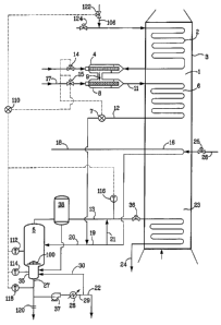
[0034] Figure 1 illustrates a schematic flow diagram of the overall process
and apparatus in accordance with the present invention employed with a
pyrolysis
furnace.
DETAILED DESCRIPTION OF THE INVENTION
[0035] Unless otherwise stated, all percentages, parts, ratios, etc., are by
weight. Unless otherwise stated, a reference to a compound or component
includes the compound or component by itself, as well as in combination with
other compounds or components, such as mixtures of compounds.
[0036] Further, when an amount, concentration, or other value or parameter
is given as a list of upper preferable values and lower preferable values,
this is to
CA 02567168 2006-11-17
WO 2005/113721 PCT/US2005/017695
-11-
be understood as specifically disclosing all ranges formed from any pair of an
upper preferred value and a lower preferred value, regardless of whether
ranges
are separately disclosed.
[0037] As used herein, resids are non-volatile components, e.g., the
fraction of the hydrocarbon feed with a nominal boiling point above 590 C
(1100 F) as measured by ASTM D-6352-98 or D-2887. This invention works
very well with non-volatiles having a nominal boiling point above 760 C
(1400 F). The boiling point distribution of the hydrocarbon feed is measured
by
Gas Chromatograph Distillation (GCD) by ASTM D-6352-98 or D-2887 extended
by extrapolation for materials boiling above 700 C (1292 F). Non-volatiles
include coke precursors, which are large, condensable molecules which condense
in the vapor, and then form coke under the operating conditions encountered in
the
present process of the invention.
[0038] The hydrocarbon feedstock with resid and coke precursors for use
with the present invention typically comprises one or more of steam cracked
gas
oil and residues, gas oils, heating oil, jet fuel, diesel, kerosene, gasoline,
coker
naphtha, steam cracked naphtha, catalytically cracked naphtha, hydrocrackate,
reformate, raffinate reformate, Fischer-Tropsch liquids, Fischer-Tropsch
gases,
natural gasoline, distillate, virgin naphtha, crude oil, atmospheric pipestill
bottoms, vacuum pipestill streams including bottoms, wide boiling range
naphtha
to gas oil condensates, heavy non-virgin hydrocarbon streams from refineries,
vacuum gas oils, heavy gas oil, naphtha contaminated with crude, atmospheric
residue, heavy residue, hydrocarbon gas/residue admixtures, hydrogen/residue
admixtures, C4's/residue admixtures, naphtha/residue admixtures, and gas
oil/residue admixtures.
[0039] In one embodiment of this aspect of the invention, the hydrocarbon
feedstock with resid and coke precursors has a nominal final boiling point of
at
least about 315 C (600 F).
CA 02567168 2006-11-17
WO 2005/113721 PCT/US2005/017695
-12-
[0040] The present invention relates to a process for heating and steam
cracking hydrocarbon feedstock containing resid. The process comprises heating
the hydrocarbon feedstock, mixing the hydrocarbon feedstock with a fluid to
form
a mixture, flashing the mixture to form a vapor phase and a liquid phase,
feeding
the vapor phase to the radiant section of a pyrolysis furnace, and
subsequently
quenching the reaction, e.g., by using a transfer line exchanger, quench oil,
or
quench water.
[0041] In one aspect, the present invention relates to a process for
removing coke formed during cracking of hydrocarbon feedstock containing resid
and coke precursors, wherein steam is added to the feedstock to form a mixture
which is thereafter separated into a vapor phase and a liquid phase by
flashing in a
flash/separation vessel. The vapor phase is then separated and cracked and the
resulting cracked product recovered. Coking of internal surfaces in and
proximally downstream of the vessel is controlled by interrupting the feed
flow,
purging the vessel with steam, introducing an air/steam mixture to at least
partially
combust the coke, and resuming the feed flow when sufficient coke has been
removed.
[0042] In another aspect, the present invention relates to a process for
removing coke formed during cracking of a hydrocarbon feedstock containing
resid and coke precursors. The process comprises (a) heating the hydrocarbon
feedstock; (b) mixing the heated hydrocarbon feedstock with a primary dilution
steam stream to form a mixture stream containing coke precursors; (c) flashing
the
mixture stream in a flash/separation vessel to form a coke precursor depleted
vapor phase and a coke precursor rich liquid phase; (d) removing the liquid
phase
through a bottom outlet and vapor phase with a trace of condensed vapor phase
through an overhead outlet in the flash/separation vessel, which vessel
comprises
internal surfaces and associated outlet piping, which surfaces and piping
become
coated during operation with said liquid phase and/or condensed vapor phase
and
thereafter at least partially coked; (e) cracking the vapor phase in a radiant
section
CA 02567168 2006-11-17
WO 2005/113721 PCT/US2005/017695
- 13-
of a pyrolysis furnace to produce an effluent comprising olefins, the
pyrolysis
furnace comprising a radiant section and a convection section; (f) quenching
the
effluent and recovering cracked product therefrom; and (g) determining the
level
of coking in the flash/separation vessel or in piping immediately downstream
of
said flash/separation vessel, and when a predetermined upper coke level is
reached
(i) interrupting flow of the hydrocarbon feedstock containing resid and coke
precursors to the flash/separation vessel, (ii) purging the flash/separation
vessel
with steam under conditions sufficient to substantially remove the vapor phase
from the vessel and the liquid phase from the internal surfaces and/or outlet
piping, (iii) introducing an air/steam mixture through the flash/separation
vessel
under conditions sufficient to at least partially combust coke on the internal
surfaces and outlet piping, and (iv) restarting the flow of the hydrocarbon
feedstock to the flash/separation vessel when a predetermined lower coke level
on
the internal surfaces and/or outlet piping is reached.
[0043] In an embodiment of this aspect of the present invention, the
flash/separation vessel comprises a baffle positioned above the liquid outlet
which
carries liquid outward and from the center of the vessel and downward.
Typically,
the baffle can be of any suitable shape, e.g., a substantially conical baffle
whose
apex points up, effecting the desired flow of liquid outward and downward. The
baffle can be perforated, typically comprising perforations substituting for
at least
about 1 % of the total surface area of a corresponding unperforated baffle. In
another embodiment of this aspect of the present invention, the
flash/separation
vessel is substantially cylindrical. The mixture stream is introduced to the
flash/separation vessel in a suitable manner, typically, by introducing the
mixture
stream (i) tangentially through at least one side inlet located in the side of
the
vessel, (ii) radially through at least one side inlet located in the side of
the vessel,
(iii) through the top of the vessel, and/or (iv) through the bottom of the
vessel, and
the vapor phase is removed through an overhead outlet of the vessel. In one
embodiment, the mixture stream is introduced tangentially to the
flash/separation
CA 02567168 2006-11-17
WO 2005/113721 PCT/US2005/017695
-14-
vessel through at least one side inlet located in the side of said vessel,
while the
vapor phase is removed through an overhead outlet of the vessel.
[0044] The heating of the hydrocarbon feedstock can take any form known
by those of ordinary skill in the art. However, as shown in the Figure, it is
preferred that the heating comprises indirect contact of the hydrocarbon
feedstock
in the upper (farthest from the radiant section) convection section tube bank
2 of
the furnace 1 with hot flue gases from the radiant section of the furnace.
This can
be accomplished, by way of non-limiting example, by passing the hydrocarbon
feedstock through a bank of heat exchange tubes 2 located within the
convection
section 3 of the furnace 1. The temperature of the hydrocarbon feedstock with
resid and coke precursors is typically from about 150 to about 340 C (300 to
650 F) before mixing with the primary dilution steam stream, preferably
between
about 150 and about 260 C (300 and 500 F), such as about 160 to about 230 C
(325 to 450 F), for example about 170 to about 220 C (340 to about 425 F).
[0045] The heated hydrocarbon feedstock is mixed with primary dilution
steam and optionally, a fluid which can be a hydrocarbon, preferably liquid
but
optionally vapor; water, steam, or a mixture thereof. The preferred fluid is
water.
A source of the fluid can be low pressure boiler feed water. The temperature
of
the fluid can be below, equal to, or above the temperature of the heated
feedstock.
[0046] The mixing of the heated hydrocarbon feedstock and the fluid can
occur inside or outside the pyrolysis furnace 1, but preferably it occurs
outside the
furnace. The mixing can be accomplished using any mixing device known within
the art. For example, it is possible to use a first sparger 4 of a double
sparger
assembly 9 for the mixing. The first sparger 4 can avoid or to reduce
hammering,
caused by sudden vaporization of the fluid, upon introduction of the fluid
into the
heated hydrocarbon feedstock.
[0047] The present invention uses steam streams in various parts of the
process. The primary dilution steam stream 17 can be mixed with the heated
hydrocarbon feedstock as detailed below. In another embodiment, a secondary
CA 02567168 2006-11-17
WO 2005/113721 PCT/US2005/017695
- 15-
dilution steam stream 18 can be heated in the convection section and mixed
with
the heated mixture steam before the flash. The source of the secondary
dilution
steam may be primary dilution steam that has been superheated, optionally in a
convection section of the pyrolysis furnace. Either or both of the primary and
secondary dilution steam streams may comprise sour or process steam.
Superheating the sour or process dilution steam minimizes the risk of
corrosion
that could result from condensation of sour or process steam.
[0048] In one embodiment of the present invention, in addition to the fluid
mixed with the heated feedstock, the primary dilution steam 17 is also mixed
with
the feedstock. The primary dilution steam stream can be preferably injected
into a
second sparger 8. It is preferred that the primary dilution steam stream is
injected
into the hydrocarbon fluid mixture before the resulting stream mixture
optionally
enters the convection section at 11 for additional heating by flue gas,
generally
within the same tube bank as would have been used for heating the hydrocarbon
feedstock.
[0049] The primary dilution steam can have a temperature greater, lower
or about the same as hydrocarbon feedstock fluid mixture but preferably the
temperature is greater than that of the mixture and serves to partially
vaporize the
feedstock/fluid mixture. The primary dilution steam may be superheated,
preferably in the convection section of the furnace, before being injected
into the
second sparger 8.
[0050] The mixture stream comprising the heated hydrocarbon feedstock,
the fluid, and the optional primary dilution steam stream leaving the second
sparger 8 is optionally heated again in the convection section of the
pyrolysis
furnace 3 before the flash. The heating can be accomplished, by way of non-
limiting example, by passing the mixture stream through a bank of heat
exchange
tubes 6 located within the convection section, usually as part of the first
convection section tube bank, of the furnace and thus heated by the hot flue
gas
from the radiant section of the furnace. The temperature of the flue gas
entering
CA 02567168 2006-11-17
WO 2005/113721 PCT/US2005/017695
-16-
the first convection section tube bank is typically less than about 815 C
(1500 F),
such as less than about 705 C (1300 F), less than about 620 C (1150 F), or
even
less than about 540 C (1000 F). The thus-heated mixture stream leaves the
convection section as a mixture stream 12 to optionally be further mixed with
an
additional steam stream.
[0051] Optionally, the secondary dilution steam stream 18 can be further
split into a flash steam stream 19 which is mixed with the hydrocarbon mixture
12
before the flash and a bypass steam stream 21 which bypasses the flash of the
hydrocarbon mixture and, instead is mixed with the vapor phase from the flash
before the vapor phase is cracked in the radiant section of the furnace. The
present
invention can operate with all secondary dilution steam 18 used as flash steam
19
with no bypass steam 21. Alternatively, the present invention can be operated
with secondary dilution steam 18 directed to bypass steam 21 with no flash
steam
19. In a preferred embodiment in accordance with the present invention, the
ratio
of the flash steam stream 19 to bypass steam stream 21 should be preferably
1:20
to 20:1, and most preferably 1:2 to 2:1. In this embodiment, the flash steam
19 is
mixed with the hydrocarbon mixture stream 12 to form a flash stream 20 which
can be introduced tangentially before the flash in flash/separator vessel 5.
Preferably, the secondary dilution steam stream is superheated in a
superheater
section 16 in the furnace convection before splitting and mixing with the
hydrocarbon mixture. The addition of the flash steam stream 19 to the
hydrocarbon mixture stream 12 aids the vaporization of most volatile
components
of the mixture before the flash stream 20 enters the flash/separator vessel 5.
[0052] Very high volatility feedstocks (e.g., ultra light crudes and
contaminated condensates) can be heated in tube bank 2 of convection section 1
forming a vapor and a liquid phase and conveyed as stream 12 directly to the
separation vessel 5 without mixing with dilution steam 17 or fluid.
[0053] The.mixture stream 12 or the flash stream 20 is then flashed, for
example in a flash/separator vessel 5, for separation into two phases: a vapor
CA 02567168 2006-11-17
WO 2005/113721 PCT/US2005/017695
-17-
phase comprising predominantly volatile hydrocarbons and steam and a liquid
phase comprising predominantly non-volatile hydrocarbons. The vapor phase is
preferably removed from the flash/separator vessel as an overhead vapor stream
13. The vapor phase, preferably, is fed via control valve 36 to a convection
section tube bank 23 of the furnace, preferably located nearest the radiant
section
of the furnace, for optional heating and through crossover pipes 24 to the
radiant
section of the pyrolysis furnace for cracking. The liquid phase of the flashed
mixture stream is removed from the flash/separator vessel 5 as a bottoms
stream
27.
[0054] It is preferred to maintain a predetermined constant ratio of vapor
to liquid in the flash/separator vessel 5, but such ratio is difficult to
measure and
control. As an alternative, temperature of the mixture stream 12 before the
flash/separator vessel 5 can be used as an indirect parameter to measure,
control,
and maintain an approximately constant vapor-to-liquid ratio in the
flash/separator
vessel 5. Ideally, when the mixture stream temperature is higher, more
volatile
hydrocarbons will be vaporized and become available, as a vapor phase, for
cracking. However, when the mixture stream temperature is too high, more heavy
hydrocarbons will be present in the vapor phase and carried over to the
convection
furnace tubes, eventually coking the tubes. If the mixture stream 12
temperature
is too low, resulting in a low ratio of vapor to liquid in the flash/separator
vessel 5,
more volatile hydrocarbons will remain in liquid phase and thus will not be
available for cracking.
[0055] The mixture stream temperature is controlled so as to maximize
recovery/vaporization of volatiles in the feedstock while avoiding excessive
coking in the furnace tubes or coking in piping and vessels conveying the
mixture
from the flash/separator vessel to the furnace 1 via line 13. The pressure
drop
across the piping and vessels 13 conveying the mixture to the lower convection
section 23, and the crossover piping 24, and the temperature rise across the
lower
convection section 23 may be monitored to detect the onset of coking problems.
CA 02567168 2006-11-17
WO 2005/113721 PCT/US2005/017695
- 18-
For instance, when the crossover pressure and process inlet pressure to the
lower
convection section 23 begins to increase rapidly due to coking as indicated by
a
rapid opening of control valve 36, the temperature in the flash/separator
vessel 5
and the mixture stream 12 should be reduced or the feed rate reduced. If
coking
occurs in the lower convection section, the temperature of the flue gas to the
superheater 16 increases, requiring more desuperheater water 26.
[0056] The selection of the mixture stream 12 temperature is also
determined by the composition of the feedstock materials. When the feedstock
contains higher amounts of lighter hydrocarbons, the temperature of the
mixture
stream 12 can be set lower. As a result, the amount of fluid used in the first
sparger 4 would be increased and/or the amount of primary dilution steam used
in
the second sparger 8 would be decreased since these amounts directly impact
the
temperature of the mixture stream 12. When the feedstock contains a higher
amount of non-volatile hydrocarbons, the temperature of the mixture stream 12
should be set higher. As a result, the amount of fluid used in the first
sparger 4
would be decreased while the amount of primary dilution steam used in the
second
sparger 8 would be increased. By carefully selecting a mixture stream
temperature, the present invention can find applications in a wide variety of
feedstock materials.
[0057] Typically, the temperature of the mixture stream 12 can be set and
controlled at between about 315 and about 560 C (600 and 1040 F), such as
between about 370 and about 510 C (700 and 950 F), for example between about
400 and about 480 C (750 and 900 F), and often between about 430 and about
475 C (810 and 890 F). These values will change with the concentration of
volatiles in the feedstock as discussed above.
[0058] Considerations in determining the temperature include the desire to
maintain a liquid phase to reduce the likelihood of coke formation on
exchanger
tube walls and in the flash/separator.
CA 02567168 2006-11-17
WO 2005/113721 PCT/US2005/017695
-19-
[0059] The temperature of mixture stream 12 can be controlled by a
control system 7 which comprises at least a temperature sensor and any known
control device, such as a computer application. Preferably, the temperature
sensors are thermocouples. The control system 7 communicates with the fluid
valve 14 and the primary dilution steam valve 15 so that the amount of the
fluid
and the primary dilution steam entering the two spargers can be controlled.
[0060] In order to maintain a constant temperature for the mixture stream
12 mixing with flash steam 19 and entering the flash/separator vessel to
achieve a
constant ratio of vapor to liquid in the flash/separator vessel 5, and to
avoid
substantial temperature and flash vapor-to-liquid ratio variations, the
present
invention operates as follows: When a temperature for the mixture stream 12
before the flash/separator vessel 5 is set, the control system 7 automatically
controls the fluid valve 14 and primary dilution steam valve 15 on the two
spargers. When the control system 7 detects a drop of temperature of the
mixture
stream, it will cause the fluid valve 14 to reduce the injection of the fluid
into the
first sparger 4. If the temperature of the mixture stream starts to rise, the
fluid
valve will be opened wider to increase the injection of the fluid into the
first
sparger 4. In one possible embodiment, the fluid latent heat of vaporization
controls mixture stream temperature.
[0061] When the primary dilution steam stream 17 is injected to the
second sparger 8, the temperature control system 7 can also be used to control
the
primary dilution steam valve 15 to adjust the amount of primary dilution steam
stream injected to the second sparger 8. This further reduces the sharp
variation of
temperature changes in the flash 5. When the control system 7 detects a drop
of
temperature of the mixture stream 12, it will instruct the primary dilution
steam
valve 15 to increase the injection of the primary dilution steam stream into
the
second sparger 8 while valve 14 is closed more. If the temperature starts to
rise,
the primary dilution steam valve will automatically close more to reduce the
CA 02567168 2006-11-17
WO 2005/113721 PCT/US2005/017695
-20-
primary dilution steam stream injected into the second sparger 8 while valve
14 is
opened wider.
[0062] In one embodiment in accordance with the present invention, the
control system 7 can be used to control both the amount of the fluid and the
amount of the primary dilution steam stream to be injected into both spargers.
[0063] In an example embodiment where the fluid is water, the controller
varies the amount of water and primary dilution steam to maintain a constant
mixture stream temperature 12, while maintaining a constant ratio of H2O
(water+steam)-to-feedstock in the mixture 11. To further avoid sharp variation
of
the flash temperature, the present invention also preferably utilizes an
intermediate
desuperheater 25 in the superheating section of the secondary dilution steam
in the
furnace. This allows the superheater 16 outlet temperature to be controlled at
a
constant value, independent of furnace load changes, coking extent changes,
excess oxygen level changes, and other variables. Normally, this desuperheater
25
maintains the temperature of the secondary dilution steam between about 425
and
about 590 C (800 and 1100 F), for example between about 455 and about 540 C
(850 and 1000 F), such as between about 455 and about 510 C (850 and 950 F),
and typically between about 470 and about 495 C (875 and 925 F). The
desuperheater can be a control valve and optional water atomizer nozzle. After
partial preheating, the secondary dilution steam exits the convection section
and a
fine mist of water 26 can be added which rapidly vaporizes and reduces the
temperature. The steam is preferably then further heated in the convection
section. The amount of water added to the superheater can control the
temperature
of the steam which is mixed with mixture stream 12.
[0064] Although the description above is based on adjusting the amounts
of the fluid and the primary dilution steam streams injected into the
hydrocarbon
feedstock in the two spargers 4 and 8, according to the predetermined
temperature
of the mixture stream 12 before the flash/separator vessel 5, the same control
mechanisms can be applied to other parameters at other locations. For
instance,
CA 02567168 2006-11-17
WO 2005/113721 PCT/US2005/017695
-21-
the flash pressure and the temperature and the flow rate of the flash steam 19
can
be changed to effect a change in the vapor-to-liquid ratio in the flash. Also,
excess
oxygen in the flue gas can also be a control variable, albeit, possibly a slow
one.
[0065] In addition to maintaining a constant temperature of the mixture
stream 12 entering the flash/separator vessel, it is generally also desirable
to
maintain a constant hydrocarbon partial pressure of the flash stream 20 in
order to
maintain a constant ratio of vapor to liquid in the flash/separator vessel. By
way
of examples, the constant hydrocarbon partial pressure can be maintained by
maintaining constant flash/separator vessel pressure through the use of
control
valves 36 on the vapor phase line 13, and by controlling the ratio of steam to
hydrocarbon feedstock in stream 20. The vapor phase line 13 contains a trace
of
condensed vapor phase in addition to the vapor phase. These trace amounts of
condensed vapor phase are typically less than about 3 wt%, such as less than
about
1 wt% of the total overhead stream. However, their presence is highly
undesirable
inasmuch as these condensates act as coke precursors.
[0066] Typically, the hydrocarbon partial pressure of the flash stream in
the present invention is set and controlled at between about 25 and about 830
kPa
(4 and 120 psia), such as between about 35 and about 100 kPa (5 and 15 psia),
for
example between about 40 and about 75 kPa (6 and 11 psia).
[0067] In one embodiment, the flash is conducted in at least one
flash/separator vessel. Typically the flash is a one-stage process with or
without
reflux. The flash/separator vessel 5 is normally operated at about 275 to
about
1400 kPag (40 to 200 psig) pressure and its temperature is usually the same or
slightly lower than the temperature of the flash stream 20 before entering the
flash/separator vessel 5. Typically, the temperature at which the
flash/separator
vessel operates is about 310 to about 540 C (600 to about 1000 F). For
example,
the pressure of the flash can be about 600 to about 1100 kPa (85 to 155 psia)
and
the temperature can be about 370 to about 490 C (700 to 920 F). As a further
example, the pressure of the flash can be about 700 to about 1000 kPa (105 to
145
CA 02567168 2006-11-17
WO 2005/113721 PCT/US2005/017695
-22 -
psia) with a temperature of about 400 to about 480 C (750 to 900 F). In yet
another example, the pressure of the flash/separator vessel can be about 700
to
about 760 kPa (105 to 125 psia) and the temperature can be about 430 to about
475 C (810 to 890 F). Depending on the temperature of the mixture stream 12,
generally about 50 to about 98% of the mixture stream being flashed is in the
vapor phase, such as about 60 to about 95%, for example about 65 to about 90%.
[0068] The flash/separator vessel 5 is generally operated, in one aspect, to
minimize the temperature of the liquid phase at the bottom of the vessel
because
too much heat may cause coking of the non-volatiles in the liquid phase. Use
of
the secondary dilution steam stream 18 in the flash stream entering the
flash/separator vessel lowers the vaporization temperature because it reduces
the
partial pressure of the hydrocarbons (i.e., a larger mole fraction of the
vapor is
steam) and thus lowers the required liquid phase temperature. It may also be
helpful to recycle a portion of the externally cooled flash/separator vessel
bottoms
liquid 30 back to the flash/separator vessel to help cool the newly separated
liquid
phase at the bottom of the flash/separator vessel 5. Stream 27 can be conveyed
from the bottom of the flash/separator vessel 5 to the cooler 28 via pump 37.
The
cooled stream 29 can then be split into a recycle stream 30 and export stream
22.
The temperature of the recycled stream would typically be about 500 to about
600 F (260 to 315 C), for example 520 to 550 F (270 to 290 C). The amount of
recycled stream can be about 80 to about 250% of the amount of the newly
separated bottom liquid inside the flash/separator vessel, such as 90 to 225%,
for
example, 100 to 200%.
[0069] The flash is generally also operated, in another aspect, to minimize
the liquid retention/holding time in the flash vessel. In one example
embodiment,
the liquid phase is discharged from the vessel through a small diameter "boot"
or
cylinder 35 on the bottom of the flash/separator vessel. Typically, the liquid
phase
retention time in the drum is less than 75 seconds, for example, less than 60
seconds, such as less than 30 seconds, and often less than 15 seconds. The
shorter
CA 02567168 2006-11-17
WO 2005/113721 PCT/US2005/017695
-23-
the liquid phase retention/holding time in the flash/separator vessel, the
less
coking occurs in the bottom of the flash/separator vessel.
[0070] Although it is the preferred embodiment for stream 27 to flow out
of the bottom of the boot 35, stream 27 can be can be located as a side
drawoff the
boot 35 or the low section of flash/separator vessel 5.
[0071] Inasmuch as the present invention relates to controlling coking
within the flash/separator vessel 5, it is noted that optimizing the cut made
by the
flash/separator vessel typically employs conditions of high temperatures and
convection pressures. These conditions are conducive to the formation of coke
by
thermal cracking on the vessel internals, e.g., baffles and walls. In one
embodiment of the invention, a substantially conical baffle 100, which is
advantageously perforated, employed for the purpose of reducing or avoiding
entrainment of liquid in the overhead, is subjected to coking of its surfaces.
Moreover, coke laydown in the outlet piping (overhead outlet associated with
that
portion of vapor phase line 13 downstream of line 21 and bottom outlet
associated
with liquid phase line 27) immediately downstream of the vessel 5 is enhanced
by
steam stripping of the lighter components in the vessel overhead stream by
bypass
steam 21 injected in the overhead stream. Coke forming in the flash/separator
vessel 5 and its adjacent downstream piping can be removed by techniques such
as
hydroblasting which requires shutdown of the furnace 1 for hydroblasting of
the
vessel internals and associated piping by introducing water (not shown) to the
vessel. Such techniques typically require long shutdown times followed by
steam
purging before restarting the process.
[0072] In one embodiment of the present invention, the sensors comprise
sensor 112 and sensor 114 within the vessel 5 or its boot 35. Sensors may also
be
positioned downstream of the vessel, e.g., downstream of where bypass stream
is
introduced to overhead at 116 or at 118 downstream of the boot 35 which allows
monitoring the bottoms slipstream temperature of the flash/separation vessel.
The
sensors are typically surface thermocouples associated with the inside of the
CA 02567168 2009-12-16
-24-
flash/separation vessel 5 or associated piping. In order to effectively remove
coke,
the temperature of the air/steam mixture is typically controlled to be hot
enough to
combust the coke, such as about 480 C (896 F). The air/steam ratio is
typically
controlled to less than about 0.2 to limit flame temperatures to about 570 to
about
615 C (1060 to 1 140 F) and the temperature of the bottoms slip stream to
about
550 C (1025 F) so as not to exceed the allowable design temperature of the
flash/separation vessel and its associated piping. Once the vessel is decoked,
the
air to steam rate can be increased to about 0.5. In order to effectively
decoke the
baffle 100 it is advantageous to provide a slipstream, such as about 10% of
the
air/steam mixture through the baffle perforations and around the baffle
perimeter
and out through the bottom outlet as stream 27 whose flow can be controlled by
restriction orifices 120. The remaining 90% of the air/steam mixture can pass
as
overhead via 13 whose flow optionally can be controlled by 36. Both the
overhead and bottom flow of the air/steam mixture can be controlled by
controller
110, such as a function of temperatures registered by one or more of the
sensors.
Finally, controller 110 can interrupt the flow of hydrocarbon feedstock
through a
valve and lines 122 and 106, effect steam purge, and then resume the flow of
hydrocarbon feedstock by valve 124 during the process as a function of coke
levels
within the vessel and associated piping, in accordance with the present
invention.
(0073) Turning from the subject of controlling coking within the
flash/separator vessel 5 and its associated piping, and considering the
further
processing of the vapor phase taken as overhead from the vessel, it is noted
that
the vapor phase may contain, for example, 55 to 70% hydrocarbons and 30 to 45%
steam. The boiling end point of the vapor phase is normally below about 760 C
(1400 F), such as below about 590 C (1100 F), and often below about 565 C
(1050 F). The vapor phase is continuously removed from the flash/separator
vessel 5 through an overhead pipe, which optionally conveys the vapor to a
centrifugal separator 38 to remove trace amounts of entrained and/or condensed
CA 02567168 2006-11-17
WO 2005/113721 PCT/US2005/017695
-25-
liquid. The vapor then typically flows into a manifold that distributes the
flow to
the convection section of the furnace.
[0074] The vapor phase stream 13 continuously removed from the
flash/separator vessel is preferably superheated in the pyrolysis furnace
lower
convection section 23 to a temperature of, for example, about 425 to about 705
C
(800 to 1300 F) by the flue gas from the radiant section of the furnace. The
vapor
phase is then introduced to the radiant section of the pyrolysis furnace to be
cracked.
[0075] The vapor phase stream 13 removed from the flash/separator vessel
can optionally be mixed with a bypass steam stream 21 before being introduced
into the furnace lower convection section 23.
[0076] The bypass steam stream 21 is a split steam stream from the
secondary dilution steam 18. Preferably, the secondary dilution steam is first
heated in the convection section of the pyrolysis furnace 3 before splitting
and
mixing with the vapor phase stream removed from the flash 5. The superheating
after the mixing of the bypass steam 21 with the vapor phase stream 13 ensures
that all but the heaviest components of the mixture in this section of the
furnace
are vaporized before entering the radiant section. Raising the temperature of
vapor phase to between about 425 and about 705 C (800 to 1300 F) in the lower
convection section 23 also helps the operation in the radiant section since
radiant
tube metal temperature can be reduced. This results in less coking potential
in the
radiant section. The superheated vapor is then cracked in the radiant section
of the
pyrolysis furnace.
[0077] The overhead vapor from the flash/separation vessel is optionally
heated to a sufficient temperature for passing to the radiant (cracking) zone
of the
pyrolysis furnace. In the radiant zone the feed is thermally cracked to
produce an
effluent comprising olefins, including ethylene and other desired light
olefins, and
byproducts which is passed to a recovery train for recovery of products as
known
in the art.
CA 02567168 2006-11-17
WO 2005/113721 PCT/US2005/017695
-26-
[0078] While the present invention has been described and illustrated by
reference to particular embodiments, those of ordinary skill in the art will
appreciate that the invention lends itself to variations not necessarily
illustrated
herein. For this reason, then, reference should be made solely to the appended
claims for purposes of determining the true scope of the present invention.