Note: Descriptions are shown in the official language in which they were submitted.
CA 02567296 2006-11-16
WO 2005/112821 PCT/US2005/017878
-1-
ENHANCED BIOLOGICAL FIXATION OF GRAFTS
Description
Technical Field
This invention relates to a graft material and more particularly to a graft
material with enhanced or improved potential for biological fixation on or in
the
human or animal body.
Background of the Invention
This invention will be generally discussed in relation to its application to
endoluminally deployed grafts and stent grafts but the invention is not so
limited
and can also be applied to the grafts to be applied to or in the human or
animal
body and where biological fixation is a desired or necessary function.
Stent grafts for endoluminal deployment into body lumens of a human
or animal are generally formed from a tube of a biocompatible material and a
stent
or stents to maintain a lumen therethrough. Such grafts are used to span a
damaged portion of the lumen such as an abdominal aortic aneurysm. Generally
the stent graft engages against the wall of the lumen either side of the
aneurysm
in a region referred to as a landing zone. It is desirable to have some
fixation to the
wall of the lumen in the landing zone to ensure that the stent graft will not
migrate.
In particular, proximal fixation in the neck region of the aorta ofan
abdominal aortic
aneurysm stent-graft is a critical function with respect to long term
durability of
endovascular repair. This is important because pulsating blood in the aorta
can
provide considerable forces on a stent graft. Ineffective fixation can result
in stent-
graft migration which can lead to subsequent type I endoleaks and the real
possibility of subsequent intervention required by the physician to repair the
leaks.
The present solutions to the problem of fixation mostly depend on mechanical
anchoring mechanisms. Frictional forces between the stent-graft and aorticwall
are
created by the interference fit between the diameters of the stent-graft and
aorta
wall supported by the underlying stent or stents. The practice of over-sizing
a
device forthe lumen into which it is to be placed is directly related to the
intentional
creation of these frictional holding forces. The second significant fixation
force is
CA 02567296 2006-11-16
WO 2005/112821 PCT/US2005/017878
-2-
related to small hooks or barbs which completely penetrate the arterial wall.
In both
cases, the fixation force provided is immediate and does not require long term
biological interaction. A third fixation force, tissue encapsulation, occurs
in some
devices over a much longer time frame (up to many months or even years).
Exposed stainless steel stent struts, such as the renal stent in some forms of
abdominal aortic aneurysm (AAA) stent-graft device, eventually become
completely
encapsulated (each strut is surrounded) bytissue growth resulting in
additional and
significant fixation. The interference fit and to some extent encapsulation
mechanism provide sealing required to exclude the aneurysm which isthe purpose
of the device. There is a further problem that through the complex
physiological
process of arterial disease and aneurysm growth, frictional forces can be
negated
by the loss of the interference fit discussed above. That is, the neck of the
aorta can
further dilate due to disease, normal aging or the outward force of the stent.
Thus
over time it is possible to lose some or all of these mechanical normal
forces. In
addition, the fixation provided by barbs can be under risk due to the
corrosion of
the solder material and local tearing of the aortic wall.
Cell ingrowth into graft materials is sought for many different medical
device applications. The biocompatible material forms a barrier that cells
might be
able to attach to, but cannot grow into. In the case of a vascular graft, cell
ingrowth
is important to avoid the formation of thrombus, create a seal, and to secure
the
graft intra or interluminally. The most thrombo-resistant material known is a
monolayer of endothelial cells. Without cell ingrowth into a graft, it is has
been
virtually impossible to achieve a monolayer of endothelial cells using
traditional
graft materials.
Also, without cellular ingrowth, fixation and sealing of the device is left
to mechanical means, which could fail over time.
Currently, for large diameter grafts such as AAA grafts, the trend is to use
expanded poly tetrafluoethylene (ePTFE) or Dacron fabric with minimal
porosity.
Tissue ingrowth has been sacrificed to ensure that type IV endoleaks (leakage
due
to high porosity graft material) are eliminated. Fixation and sealing are
achieved
CA 02567296 2006-11-16
WO 2005/112821 PCT/US2005/017878
-3-
through mechanical means as discussed above and thrombus is not seen as an
eminent concern due to the high flow rate in large diameter grafts.
It is an object of this invention provides a biological fixation mechanism
which does
not rely on these secondary mechanical anchoring forces or to at least provide
a
physician with an alternative fixation mechanism.
Throughout this specification the term distal with respect to a portion of
the aorta, a deployment device or a prosthesis is the end of the aorta,
deployment
device or prosthesis further away in the direction of blood flow away from the
heart
and the term proximal means the portion of the aorta, deployment device or end
of the prosthesis nearer to the heart. When applied to other vessels similar
terms
such as caudal and cranial should be understood.
Summary of the Invention
In one form therefore the invention resides in a stent graft comprising a
substantially tubular body having a proximal end and a distal end, at least
the
proximal end comprising a region intended in use to engage a landing zone in a
vessel in the body in use, the region comprising a mechanical treatmentto
enhance
biological fixation to the landing zone.
The mechanical treatment can be selected from the group comprising
provision of apertures, provision of relatively rigid, as hereinafter
described,
engagement portions, impregnation with a SIS gel or digest and mounting of a
SIS
cuff or collar.
In an alternate form the invention comprises a stent graft comprising a
substantially tubular body having a proximal end and a distal end, at least
the
proximal end comprising a plurality of relatively rigid engagement portions
extending radially outward therefrom to engage a landing zone in a vessel in
the
body in use.
Preferably the plurality of relatively rigid engagement portions are placed
on that portion of the stent graft which in use is expected to engage against
the
landing zone of the vessel as discussed above.
CA 02567296 2006-11-16
WO 2005/112821 PCT/US2005/017878
-4-
In this specification the term relatively rigid is intended to mean that the
engagement portions are made from a material which when engaged against the
wall of a lumen into which the stent graft is deployed deforms the wall at the
region
of engagement of the engagement portion. Hence the material of the engagement
portions should be more rigid than the vessel walls.
The engagement portions may be comprised of a metal, synthetic fiber
or thread or a polymeric material.
The engagement portions may be in the form of loops, coils, angled
portions, buttons, spikes or other protrusions or the like.
The engagement portions may be formed onto the tubular body by
stitching, adhesion or threading a further material or extra portions of the
same
material of the graft into the material of the tubular body.
Preferably the engagement portions are resilient so that they can be
compressed into a introducer device for endoluminal deployment.
Although the process by which enhanced biological fixation is not fully
understood it is suggested that the process may be as follows. The engagement
portions provide a matrix of radially outward protruding portions when the
stent
graft is deployed and a stent associated with the graft is providing radially
outward
pressure. These protruding portions create a localized pressure (greater than
30
mmHg-to overcome capillary pressure) against the aorta wall initiating cell
necrosis. After cell death the protruding portions will continue to impinge on
the
arterial wall leading to endothelial wall remodeling to accommodatethe
protruding
portions. Each protruding portion may in time become completely encapsulated
by
tissue growth. In effect, the protruding portions introduced on the outside of
the
graft serve as scaffold for tissue (adventitia) to grow around each protruding
portions creating a significant fixation and sealing mechanism.
In some embodimentsthe process of mounting the engagement portions
onto the tubular body may create "micro-dimensional" through-thickness holes
or
pores which will encourage cells to grow into and through the graft and
achieve
further biological fixation and sealing.
CA 02567296 2006-11-16
WO 2005/112821 PCT/US2005/017878
-5-
In a further form the invention is said to reside in a stent graft comprising
a substantially tubular body of a biocompatible graft material, the tubular
body
having a proximal end and a distal end, the proximal end including an array of
resilient wire loops extending radially outward from the tubular body.
Preferably each wire loop is formed from a stainless steel or Nitinol wire.
The each wire loop may be in the form of a semicircle, a coil, an angled
portion or the like.
At least some of the loops may be cut or otherwise severed to provide
spike portions. The use of spikes to intentionally irritate the vessel wall is
so that
faster cell response may be expected. This may be critical for old patients,
considering the fact that thrombosis/calcification may occur on the vessel
wall and
the cells in their vessels are not so aggressive as might be expected. The
number
and location of the spikes can be varied.
The wire may have a diameter of from 3 to 10 microns and the loops
formed on the tubular body may extend from the tubular body from 50 to 200
microns.
The wire loops may be formed onto the tubular body by stitching,
adhesion or threading into the weave of biocompatible material.
The biocompatible graft material may be Dacron, expanded
polytetrafluoroethylene (ePTFE), other synthetic biocompatible materials or a
naturally occurring biomaterial, such as collagen. A specially derived
collagen
material known as an extracellular matrix (ECM), such as small intestinal
submucosa (SIS) is particularly preferred. Besides SIS, examples of ECM's
include
pericardium, stomach submucosa, liver basement membrane, urinary bladder
submucosa, tissue mucosa, and dura mater.
Hence it will be seen that by this invention there is provided a fixation
mechanism that does not rely upon purely mechanical forces to prevent movement
but is based on arterial tissue growth through the scaffolding created by the
stitched loops or other types of engagement portion as well as direct tissue
in-
growth through the pores created by the stitching process.
CA 02567296 2006-11-16
WO 2005/112821 PCT/US2005/017878
-6-
In a further form the invention is said to reside in a graft comprising a
synthetic biocompatible graft material, at least a portion ofthe graft
material having
a biologically active material associated therewith.
This biologically active material will promote tissue re-growth and
remodeling at an accelerated pace. Hence this invention supplements the
current
fixation techniques by providing an enhanced biological fixation and sealing
mechanism. In effect tissue growth into the synthetic graft material is
promoted by
the presence of the biologically active material. In the case of a stent graft
this
biological fixation enhancement can be localized to the proximal and distal
neck
regions where attachment is critical for fixation and sealing. The fixation
and
sealing of a graft incorporating the biological fixation enhancement of the
present
invention is biological and permanent and does not require a long term and
less
reliable mechanical fixation mechanism which are problematic at best.
Various methods and designs can be used to associate the biologically
active material with the synthetic graft material. Methods can include
attaching,
infusing, encapsulation, etc. the biologically active material to the graft
material in
ways that will survive the manufacturing process and be delivered to the neck
region, for instance of a stent graft, intact until the tissue in-growth and
biological
fixation is complete.
The graft may be in a form of a stent graft and the biologically active
material can be associated with the graft material at at least a proximal
region of
the stent graft in a region which may be referred to as a landing zone for
engagement with a vessel wall. The biologically active material can also be
associated with the graft material at a distal region landing zone.
The synthetic biocompatible material may be Dacron or expanded
polytetrafluoroethylene.
The biologically active material may be formed from a naturally occurring
biomaterial, such as collagen, particularly a specially derived collagen
material
known as an extracellular matrix (ECM), such as small intestinal submucosa
(SIS).
CA 02567296 2006-11-16
WO 2005/112821 PCT/US2005/017878
-7-
Besides SIS, examples of ECM's include pericardium, stomach submucosa, liver
basement membrane, urinary bladder submucosa, tissue mucosa, and dura mater.
SIS is particularly useful, and can be made in the fashion described in
Badylaketal., US Patent 4,902,508; Intestinal Collagen Layer described in US
Patent
5,733,337 to Carr and in 17 Nature Biotechnology 1083 (Nov. 1999); Cook et
al.,
WIPO Publication WO 98/22158, dated 28 May 1998, which is the published
application of PCT/US97/14855. In addition to xenogenic biomaterials, such as
SIS,
autologous tissue can be harvested as well. Additionally Elastin or Elastin-
Like
Polypetides (ELPs) and the like offer potential as a biologically active
material.
Another alternative would be to use allographs such as harvested native valve
tissue. Such tissue is commercially available in a cryopreserved state.
A first method by which a biologically active material can be associated
with the synthetic biocompatible graft material may be by infusing a SIS gel
into
the relatively porous graft. The natural porosity of a woven fabric (which can
be
altered by various weaving strategies) can allow the infusing into the graft
of a SIS
gel by applying a vacuum on one side of the graft and "pulling" the SIS gel
into the
interstices which form the natural porosity of the graft.
A second method by which a biologically active material can be
associated with the synthetic biocompatible graft material may be byvacuum
press
a SIS sheet onto the synthetic graft material with the use of a SIS gel as an
adhesive. SIS sheet is a proven product capable of providing a collagen
scaffolding
enhanced with natural porcine growth factors and other proteins. The use of
SIS gel
as a "glue" both connects the SIS sheet to the graft as well as promoting
further
tissue-graft in-growth. One possible manufacturing process is to apply the SIS
gel
and SIS sheet on to the outside of the graft and then "vacuum-pull" the graft
so
that SIS gel can penetrate the graft, subsequently polymerize the composite
graft
in the oven at 37 C for 20 minutes and then freeze dry and /or vacuum press
the
composite graft.
A third method by which a biologically active material can be associated
with the synthetic biocompatible graft material may be by attaching SIS sheet
by
use of metal or synthetic biocompatible fiber or thread.
CA 02567296 2006-11-16
WO 2005/112821 PCT/US2005/017878
-8-
SIS sheet can be stitched on to a synthetic graft so as to form a secure
and permanent mechanical attachment. SIS gel can then be used as a "binder" by
following the steps described in the second method to fill the pores created
by the
stitching process and further, any protruding fibers can form a mechanical
scaffolding to hold the SIS gel in place. The stitching can be done using a
biocompatible thread such as a suture thread or by the use of a wire thread.
At least some of the stitching with the biocompatible thread such as a suture
thread
or by the use of a wire thread can extend beyond the outer surface of the
stent
graft and provide a plurality of relatively rigid engagement portions
extending
radially outward therefrom to enhance fixation.
In a further form the invention is said to reside in a graft comprising a
biocompatible graft material, at least a portion of the graft material having
a
selected porosity to allow cell in-growth and still provide an adequate short
term
seal and fixation.
In a further form the invention is said to reside in a stent graft comprising
a tubular body of a biocompatible graft material defining a lumen therethrough
and
having a proximal end and a distal end, at least a portion along the length of
the
proximal end of thetubular body having a selected porosityto allowcell in-
growth.
The porosity may be provided by an array of apertures in the biocompatible
graft
material. The aperture may have a diameter in the range of from 20 microns to
120
microns and a spacing of from 20 to 250 microns.
The apertures may be formed in the biocompatible graft material by the
use of laser drilling. Lasers provide a small beam spot, accurate drilling
depth
control, and minimum heat affected area. Excimer lasers are specifically noted
for
theirdegree of precision and minimal damageto surrounding material. Lasers
have
the capability to drill holes smaller than 50 microns at varying interpore
distances.
In an alternative form the selected porosity may be provided by modification
of the
weave pattern of the biocompatible fibres which make up the graft material.
For
instance in the case of a stent graft a region at the proximal end of the
stent graft
may be woven in such a way as to provide apertures between the warp or weft
CA 02567296 2006-11-16
WO 2005/112821 PCT/US2005/017878
-9-
fibres. Such aperture may have opening dimensions in the region of from 20
microns to 100 microns.
In a further form the invention is said to reside in a method of producing
a graft material adapted for biological fixation in the human or animal body
comprising the step of ablating a plurality of apertures into the graft
material, the
apertures having a diameter in the range of from 20 microns to 120 microns and
a
spacing of from 20 to 250 microns.
Preferably the ablation is done with a laser.
Hence it will be seen that there is provided by this invention a method of
forming a graft and a graftformed from a material that has controlled and
localized
porosity of a sufficient size that will allow cell in-growth while not being
sufficiently
porous to allow blood leaks.
In a further form the invention comprises a stent graft comprising a
substantially tubular body of a biocompatible graft material, the tubular body
having a proximal end and a distal end, at least the proximal end including a
cuff
or collar of SIS or some other biocompatible material to create a localized
pressure
on a landing zone in use thereby initiating cell necrosis and subsequent
endothelial
wall remodeling against the aorta wall to accommodate the protruding portions
to
enhance biological fixation of the stent graft to the landing zone.
Hence it will be seen that there is provided by this invention a stent graft
that has enhanced biological fixation.
Brief Description of the Drawing
This then generally describes the invention but to assist with
understanding reference will now be made to the accompanying drawings which
show preferred embodiments of the invention.
In the drawings:
Figure 1 shows a perspective view of a portion of a stent graft incorporating
a biological fixation arrangement according to one embodiment of the present
invention;
Figure 2 shows a cross sectional view of the stent graft along the line 2 - 2'
in Figure 1;
CA 02567296 2006-11-16
WO 2005/112821 PCT/US2005/017878
-10-
Figure 3 shows a perspective view of a portion of a stent graft incorporating
the biological fixation arrangements according to an alternative embodiment of
the
present invention;
Figure 4 shows a cross sectional view of the stent graft along the line 4 - 4'
in Figure 3;
Figures 5a to 5d show details of various shapes of engagement portions
according to an embodiment the present invention;
Figure 6 shows a perspective view of a portion of a stent graft incorporating
an alternative embodiment of a biological fixation arrangement according to
the
present invention;
Figure 7 shows an enlarged view of a portion of the graft material of Figure
6 showing a method by which SIS can be associated with the graft material;
Figure 8 shows an enlarged view of a portion of a graft materialshowing an
arrangement by which SIS can be associated with and into the graft material;
Figure 9 shows a second stage of the process started in Figure 8;
Figure 10 shows an enlarged view of a portion of the resulting graft material;
Figure 11 shows a perspective view of a portion of a stent graft incorporating
another embodiment of the biological fixation arrangement according to the
present invention;
Figure 12 shows an enlarged view of a portion of the graft material of Figure
11 showing how SIS can be impregnated into the graft material;
Figure 13 shows an enlarged view of a portion of the resulting graft material
of Figure 12;
Figure 14 shows a perspective view of a portion of a stent graft incorporating
an alternative embodiment of a biological fixation arrangement according to
the
present invention; and
Figure 15 shows an enlarged view of a portion of the graft material shown
in Figure 14.
Detailed Description
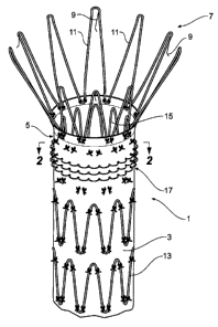
Figure 1 shows a perspective view of a portion of a stent graft incorporating
biological fixation arrangements according to one embodiment of the present
CA 02567296 2006-11-16
WO 2005/112821 PCT/US2005/017878
-11-
invention. The stent graft 1 has a tubular body 3 of a biocompatible material
such
as a woven Dacron. Along the length of the tubular body 3 there are self
expanding
Z stents 13 outside the tubular body and stitched to the tubular body. At the
proximal end 5 there is an internal self expanding Z stent 15 again stitched
to the
body. When the stent graft 1 is deployed into a vessel of a human or animal
body
such as an aorta this proximal Z stent 15 provides pressure against the wall
of the
aorta in the landing zone and with the Z stent 15 within the tubular body an
essentially smooth outer surface is presented to the wall of the aorta to
provide a
degree of initial sealing.
Atthe proximal end 5 of the stent graft 1 there is also a proximally extending
uncovered self expanding Z stent 7. This proximally extending Z stent 7 has
barbs
9 extending from struts 11 of the stent 7. When the stent graft 1 is deployed
into a
vessel of a human or animal body such as an aorta the barbs 9 engage into the
wall
of the aorta and provide a purely mechanical immediate fixation of the stent
graft
into the vessel. There is a problem with migration with pulsating blood flow,
for
instance, which may cause the barbs to tear the wall of the aorta. An added
long
term biological fixation is therefore provided according to this invention.
The added long term biological fixation is provided by a plurality of
engagement portions 17 which are fastened to the tubular body towards the
proximal end 5 thereof and which extend radially outwards from the tubular
body.
In this embodiment the plurality of engagement portions 17 are provided by
loops
of stiff polymer thread, stainless steel or Nitinol wire. The stiff polymer
thread can
for instance be a suture thread. The loops can be stitched to the tubular body
by
using a sewing machine or other similar machine. During the sewing process,
the
small loops 17 can be created on the outside of the tubular body of the stent
graft
1. There can be several rows of loops as shown in Figure 1.
Figure 2 shows a cross sectional view of the stent graft along the line 2- 2'
in Figure 1. The tubular body 3 of the stent graft 1 has the wire loops 17
stitched
into it with an internal thread 19 catching the ends of each loop.
Although a semicircular shape is shown in Figure 2, the loops can be stitched
in many shapes, and multiple bands of loops can be stitched to the areas where
the
CA 02567296 2006-11-16
WO 2005/112821 PCT/US2005/017878
-12-
maximal fixation is desired. The loops do not necessarily have to be circular
in
shape, rather can take sharper forms such as an ellipse or right angled.
Figure 3 shows a perspective view of a portion of a stent graft incorporating
the biological fixation arrangements according to an alternative embodiment of
the
present invention. In this embodiment the same reference numerals are used for
corresponding components of the embodiment shown in Figure 1.
The stent graft 1 has a tubular body 3 of a biocompatible material such as a
woven Dacron. Along the length of the tubular body 3 there are self expanding
Z
stents 13 outside the tubular body and stitched to the tubular body. At the
proximal
end 5 there is an internal self expanding Z stent 15 again stitched to the
body.
When the stent graft 1 is deployed into a vessel of a human or animal body
such
as an aorta this proximal Z stent 15 provides pressure against the wall of the
aorta
in the landing zone and with the Z stent 15 within the tubular body an
essentially
smooth outer surface is presented to the wall of the aorta to provide a degree
of
initial sealing.
At the proximal end 5 of the stent graft 1 there is also a proximally
extending
uncovered self expanding Z stent 7. This proximally extending Z stent 7 has
barbs
9 extending from struts 11 of the stent 7. When the stent graft 1 is deployed
into a
vessel of a human or animal body such as an aorta the barbs 9 engage into the
wall
of the aorta and provide a purely mechanical immediate fixation of the stent
graft
into the vessel.
An added long term biological fixation is provided according tothis invention
to provide added resistance to the force of pulsating blood.
The added long term biological fixation of this embodiment is provided by
a plurality of engagement portions 20 which are fastened to the tubular body
towards the proximal end 5 thereof in that portion which is intended to engage
with
the landing zone when deployed as discussed above and which extend radially
outwards from the tubular body. In this embodiment the plurality of engagement
portions 20 are provided by loops of stiff polymer thread, stainless steel or
Nitinol
wire. The stiff polymer thread can for instance be a suture thread. The loops
can
be stitched to the tubular body by using a sewing machine or other similar
CA 02567296 2006-11-16
WO 2005/112821 PCT/US2005/017878
-13-
machine. During the sewing process, the small metal wire loops 20 can be
created
on the outside of the tubular body of the stent graft 1. There can be several
rows
of loops as shown in Figure 3. At least some of the loops 20 are cut or
otherwise
severed at an apex of the loop to provide a pair of spikes 22 to engage
against the
wall of a vessel when deployed to intentionally irritate the vessel wall is so
that
faster cell response may be expected. This may be critical for old patients,
considering the fact that thrombosis/calcification may occur on the vessel
wall and
the cells in their vessels are not so aggressive as might be expected. The
number
and location of the spikes can be varied. In this embodiment about one in
three
loops have been cut but alternate or every loop could be formed in to spikes.
Figure 4 shows a cross sectional view of the stent graft along the line 4 - 4'
in Figure 3. The tubular body 3 of the stent graft 1 has the wire loops 20
stitched
into it with an internal wire 19 catching the ends of each loop. At least some
of the
loops are cut or otherwise formed into a spike or spikes at an apex of the
loop to
provide a pair of spikes 22 to engage against the wall of a vessel when
deployed.
Although a semicircular shape for the loops is shown in Figure 4, the metal
wire can be stitched in many shapes, and multiple rings of wire can be
stitched to
the areas where the maximal fixation is desired. The wire "loops" do not
necessarily have to be circular in shape, rather can take sharper forms such
as an
ellipse or right angled.
Figures 5a to 5d show details of various shapes of engagement portions
according to the present invention. In each case the engagement portions
extend
from the tubular body 30 of the stent graft. In Figure 5a the engagement
portions
32 are formed from a wire 34 which is stitched through the tubular body 30 in
a
series of semicircles. In Figure 5b the engagement portions 36 are formed from
a
wire 38 which is stitched through the tubular body 30 in a series of angled
portions.
In Figure 5c the engagement portions 40 are formed from a wire 42 which is
stitched through the tubular body 30 in a series of coils or helices. In
Figure 5d the
engagement portions 46 are individually formed from wires 48 which are formed
into button shapes and mounted into the tubular body 30 and stitched through
the
tubular body 30 by stitches 50.
CA 02567296 2006-11-16
WO 2005/112821 PCT/US2005/017878
-14-
As discussed earlier the material from which the engagement portions are
made is selected so that it is more rigid than the vessel wall of the vessel
into which
it is placed so that it deforms the wall, causes necrosis and tissue growth
around
the engagement portions. Thus, a material such as Nitinol in the form of a
wire may
provide an advantage due to its high degree of elastic (recoverable) strain.
Other
materials such as plastics materials, relatively stiff suture threads such as
monofilament suture thread can also be used. The materials should also be
resilient
so that they can be compressed during deployment and upon release they can
extend out to engage the wall of the aorta or other vessel.
The engagement protrusions may have nano-scale surface features which
may enhance tissue adhesion and spreading onto the surface of the engagement
protrusions.
Figure 6 shows a perspective view of a portion of a stent graft incorporating
the biological fixation arrangements according to an alternative embodiment of
the
present invention. In this embodiment the same reference numerals are used for
corresponding components of the embodiment shown in Figure 1.
The stent graft 1 has a tubular body 3 of a biocompatible material such as a
woven Dacron. Along the length of the tubular body 2 there are self expanding
Z
stents 13 outside the tubular body stitched to the tubular body. At the
proximal end
5 there is an internal self expanding Z stent 15 again stitched to the body.
When the
stent graft 1 is deployed into a vessel of a human or animal body such as an
aorta
this proximal Z stent 15 provides pressure against the wall of the aorta in
the
landing zone and as the Z stent 15 within the tubular body an essentially
smooth
outer surface is presented to the wall of the aorta to provide a degree of
sealing.
Atthe proximal end 5 of the stent graft 1 there is also a proximally extending
uncovered self expanding Z stent 7. This proximally extending Z stent 7 has
barbs
9 extending from struts 11 of the stent 7. When the stent graft 1 is deployed
into
a vessel of a human or animal body such as an aorta the barbs 9 engage into
the
wall of the aorta and provide a purely mechanical immediate fixation of the
stent
graft into the vessel. There is a problem with migration, caused by pulsating
blood
flow for instance, which may cause the barbs to tear the wall of the aorta. An
CA 02567296 2006-11-16
WO 2005/112821 PCT/US2005/017878
-15-
added long term biological fixation is therefore provided according to this
invention.
The stent graft 1 includes a sheet of SIS material 60 in the form of a cuff or
collar stitched onto the proximal end region 5 of the stent graft 1, in that
portion
which is intended to engage with the landing zone when deployed as discussed
above, by means of wire stitches 62. The wire stitches 62 retain the SIS sheet
material and have the added advantage thatthey provide apertures through the
SIS
and graft material which will permit cell growth through the material for
enhanced
biological fixation.
At least some 64 of the wire stitches 62 extend our from the surface of the
SIS sheet 60 and provide a matrix of radially outward protruding portions when
the
stent graft is deployed and a stent associated with the graft is providing
radially
outward pressure. These protruding portions may create a localised pressure
(greater than 30 mmHg-to overcome capillary pressure) against the aorta wall
initiating cell necrosis. After cell death the protruding portions will
continue to
impinge on the arterial wall leading to endothelial wall remodelling to
accommodate the protruding portions. Each protruding portion may in time
become completely encapsulated by tissue growth. In effect, the protruding
portions introduced on the outside of the graft serve as scaffold for tissue
(adventitia) to grow around each protruding portions creating a significant
fixation
and sealing mechanism.
Figure 7 shows detail of the fastening of the sheet of SIS shown on Figure 6.
In addition, however, in Figure 7 a SIS gel is used as a binder.
In this embodiment a SIS sheet is attached to a graft material by use of metal
or synthetic biocompatible fibers or threads. SIS sheet can be stitched on to
a
synthetic graft so as to form a secure and permanent mechanical attachment.
This
technique can be enhanced by using a matrix of protruding stitches. As a
further
enhancement a SIS gel can then be used as a "binder" by following the steps
described in the embodiment shown in Figures 8 to 10 to fill the pores created
by
the stitching process and further, the protruding fibers can form a mechanical
scaffolding to hold the SIS gel in place. The resulting SIS stitched composite
CA 02567296 2006-11-16
WO 2005/112821 PCT/US2005/017878
-16-
structure will encourage cell growth through the fiber loops employing all the
benefits of attachment and fixation described above.
In Figure 7 the graft material 3 in the region 61 has a cuff or collar formed
from a sheet of SIS 60 attached to it by stitching using stitches 62 which
extend
through both the SIS 60 and graft material 3 to a back stitch 66. An
intermediate
layer 68 of a SIS gel or digest can provide both a "glue" to connect the SIS
sheet
to the graft as well as promote further tissue-graft in-growth. The stitches
can be
formed from stainless steel wire, Nitinol wire or suture material. Some of the
loops
64 of the stitches 62 extend beyond the SIS to assist with biological fixation
by
engaging the wall of a vessel into which they are deployed and encouraging
tissue
growth around the loops.
Figures 8 to 10 show a further embodiment of the invention to provide
enhanced biological fixation.
In this embodiment a sheet of SIS 70 is laid over the graft material 3 in a
selected region of the stent graft with an intermediate layer 72 of a SIS gel
or
digest. A vacuum 73 is applied by means of a vacuum hood 74 and the gel or
digest 72 drawn into the graft material 3 to give the result shown in Figure 9
where
the sheet of SIS 70 is adhered to the graft material 3 using the SIS gel 72 as
an
adhesive. The composite is then polymerized by heating in an oven at 31C for
20
minutes and the resultant product is freeze dried or vacuum pressed to provide
a
product as shown on Figure 10.
SIS sheet is a proven product capable of providing a collagen scaffolding
enhanced with natural porcine growth factors and other proteins. This
manufacturing technique utilizes the SIS sheet and attaches the sheet to the
graft
material in a secure fashion. The SIS gel is used as both a "glue" to connect
the
SIS sheet to the graft as well as promote further tissue-graft in-growth as
with the
embodiment discussed above. Hence one possible manufacturing process is as
follows:
(a) apply the SIS digest and SIS sheet on to the outside of the graft and
"vacuum-pull" the graft so that SIS gel can penetrate the graft.
CA 02567296 2006-11-16
WO 2005/112821 PCT/US2005/017878
-17-
(b) polymerize the composite graft in the oven at 37 C for 20 minutes.
(c) Freeze dry and /or vacuum press the composite graft.
Figure 11 shows a perspective view of a portion of a stent graft incorporating
the biological fixation arrangements according to a further embodiment of the
present invention. In this embodiment the same reference numerals are used for
corresponding components of the embodiment shown in Figure 1.
The stent graft 1 has a tubular body 3 of a biocompatible material such as a
woven Dacron. Along the length of the tubular body 2 there are self expanding
Z
stents 13 outside the tubular body stitched to the tubular body. At the
proximal end
5 there is an internal self expanding Z stent 15 again stitched to the body.
When the
stent graft 1 is deployed into a vessel of a human or animal body such as an
aorta
this proximal Z stent 15 provides pressure against the wall of the aorta in
the
landing zone and as the Z stent 15 within the tubular body an essentially
smooth
outer surface is presented to the wall of the aorta to provide a degree of
sealing.
Atthe proximal end 5 of the stent graft 1 there is also a proximally extending
uncovered self expanding Z stent 7. This proximally extending Z stent 7 has
barbs
9 extending from struts 11 of the stent 7. When the stent graft 1 is deployed
into
a vessel of a human or animal body such as an aorta the barbs 9 engage into
the
wall of the aorta and provide a purely mechanical immediate fixation of the
stent
graft into the vessel. There is a problem with migration, caused by pulsating
blood
flow for instance, which may cause the barbs to tear the wall of the aorta. An
added long term biological fixation is therefore provided according to this
invention.
In the portion of the stent graft 1 just distal of the proximal end 5 there is
a
region 80 around the circumference of the stent graft which is intended to
engage
against the landing zone in use and which has a SIS gel or a digest of SIS
impregnated through the graft material tube 3.
Figures 12 and 13 show this process in detail. A gel or digest of SIS 82 is
applied to one surface of the graft material 3 in the region 80 and then a
vacuum
CA 02567296 2006-11-16
WO 2005/112821 PCT/US2005/017878
-18-
is applied by means of a vacuum hood 83 and the SIS gel or digest 82 is drawn
into
the graft material 3 to give the result shown in Figure 13. The natural
porosity of
the graft material can be altered by various weaving techniques to improve the
amount of infusing into the graft of the SIS or by providing additional
porosity in
selected regions of the stent graft by drilling or ablating holes in the graft
material
using a laser or similar device. Such porosity may provide openings in the
material
of from 20 to 100 microns.
The cell wall tissue can then grow into the graft material via the scaffolding
provided by the SIS. Fixation occurs as the synthetic fiber/fiber-bundles are
surrounded by new tissue growth, such as the collagen based adventitia which
forms a bio-mechanical attachment mechanism (between the graft and
arterywall).
Sealing will also be a by-product of the tissue growth through the SIS filled
graft.
In addition, it is likely that the endothelial cells will grow into the SIS on
the inside
of the graft wall forming a very smooth surface resulting in a non-
thrombogenic
graft property. Further, the resulting tissue in-growth will be biological
active
"alive" resulting in natural resistance to infection, as opposed to a purely
synthetic
graft.
Figure 14 shows a perspective view of a portion of a stent graft incorporating
the biological fixation arrangements according to an alternative embodiment of
the
present invention. In this embodiment the same reference numerals are used for
corresponding components of the embodiment shown in Figure 1.
The stent graft 1 has a tubular body 3 of a biocompatible material such as a
woven
Dacron. Along the length of the tubular body 2 there are self expanding Z
stents
13 outside the tubular body stitched to the tubular body. At the proximal end
5
there is an internal self expanding Z stent 15 again stitched to the body.
When the
stent graft 1 is deployed into a vessel of a human or animal body such as an
aorta
this proximal Z stent 15 provides pressure against the wall of the aorta in
the
landing zone and with the Z stent 15 within the tubular body an essentially
smooth
outer surface is presented to the wall of the aorta to provide a degree of
sealing.
At the proximal end 5 of the stent graft 1 there is also a proximally
extending
uncovered self expanding Z stent 7. This proximally extending Z stent 7 has
barbs
CA 02567296 2006-11-16
WO 2005/112821 PCT/US2005/017878
-19-
9 extending from struts 11 of the stent 7. When the stent graft 1 is deployed
into
a vessel of a human or animal body such as an aorta the barbs 9 engage into
the
wall of the aorta and provide a purely mechanical immediate fixation of the
stent
graft into the vessel. There is a problem with migration with pulsating blood
flow,
for instance, which may cause the barbs to tear the wall of the aorta. An
added
long term biological fixation is therefore provided according to this
invention.
In the region of the stent graft just distal of the proximal end 5 there is a
region 90
around the circumference of the stent graft which has a selected porosity
produced
by a plurality of apertures 92 through the graft material tube 3.
It is intended to have the region 90 coinciding with the intended landing zone
portion of the stent graft so that the existing low porosity of the graft
material is
maintained in the mid-graft region where the graft is open to the aneurysed
region.
Figure 15 shows an enlarged view of a portion of the graft material 3 of the
stent
graft 1. The material 3 in the region 90 has a plurality of apertures 92
ablated or
drilled into it to provide the selected porosity. In this embodiment the
apertures
have a diameter of 50 microns and a spacing of 120 microns. As discussed
earlier
the apertures may have a diameter in the range of from 20 microns to 120
microns
and a spacing of from 20 to 250 microns.
It could be advantageous to have a graft that is more porous at both the
proximal and distal ends while retaining low porosity in the midgraft region.
The
ends ofthe graftcome in contactwith the arterial wall and are important for
fixation
and sealing.
Therefore, the more porous design in the specified regions could facilitate
a bio-seal via cellular ingrowth and even edothelization on the internal
surface of
the graft wall. Tissue ingrowth through the laser drilled pores would also
provide
a bio-mechanical attachment resulting in significant long term fixation.
In a preferred embodiment of the invention the apertures can be produced
by the ablation of graft material via a photochemical laser drilling process.
The
nature of this laser is to break chemical bonds layer-by-layer, thus
vaporizing the
polymer with minimal heating. Thus minimal damage is done to the surrounding
graft material. The nature of this laser is to break chemical bonds layer-by-
layer,
CA 02567296 2006-11-16
WO 2005/112821 PCT/US2005/017878
-20-
thus vaporizing the polymer with minimal heating. It is preferable to use some
localized heating during the ablation process to provide a degree of fusing of
fibre
ends to enable the graft material to retain desired mechanical properties.
Throughout this specification various indications have been given as to the
scope of this invention but the invention is not limited to any one of these
but may
reside in two or more of these combined together. The examples are given for
illustration only and not for limitation.
Throughout this specification and the claims that follow unless the context
requires otherwise, the words 'comprise' and 'include' and variations such as
'comprising' and 'including' will be understood to imply the inclusion of a
stated
integer or group of integers but not the exclusion of any other integer or
group of
integers.