Note: Descriptions are shown in the official language in which they were submitted.
CA 02567522 2006-11-15
WO 2005/110619 PCT/SE2005/000728
1
Cooling of the motor
The present invention relates to an arrangement for a painting spindle of the
type indicated in the precharacterizing clause of Patent Claim 1. Here,
painting
spindle means above all a painting spindle for paint application, but this
does
not exclude the possibility of media other than paint being used in connection
with the invention. For the sake of simplicity, the description of the
invention
will refer to a painting spindle.
The most common area of application for such painting spindles today is the
painting of car bodies, but the spindle can of course be used in many other
cases where it may be considered suitable and possible. As far as the
construction and functioning of the painting spindle are concerned, the
spindle
is mounted on a carrier means, usually as a tool in the hand of a robot (see
Fig.
1) or in a portal, which can make it possible for the spindle to be moved
relative to the object to be painted. In principle, the painting spindle
consists,
as the name indicates, of a spindle, at the driving end of which a conical
outwardly directed bell is attached. The spindle shaft and with it the bell
are
rotated at between 6 000 and 130 000 rpm for example, and the opening of the
bell can have a diameter of between 25 and 80 mm. Paint is fed through the
spindle to the cone tip of the bell and will by virtue of the centrifugal
force
follow the inside of the bell out to its edge and there be thrown onward. In
order to apply these paint droplets to the object, for example a car body, the
paint particles are charged electrostatically and the object is earthed. The
electrostatic charging potential relative to earth (object being painted)
normally
lies in the range of 30 000 to 130 000 volts. The paint particles which leave
the
bell are attracted by the object to be painted owing to the potential
difference
between the object and the paint particles. In order to deflect the charged
paint
particles, which will leave the bell in the radial direction owing to the
rotation
of the bell, a shaping airflow is supplied on the outside behind the bell,
which
airflow is essentially axially directed and thus forces the paint particle
flow to
be deflected towards the object from the bell. The electrostatic charging is
usually brought about by the spindle being charged electrostatically, which
means that the paint particles also become charged. Alternatively, the paint
particles can be charged, after having left the bell, via rod antennas
arranged,
for example, in a circle around the part through which the paint particles
pass
CA 02567522 2006-11-15
WO 2005/110619 PCT/SE2005/000728
2
on their way to the object to be painted. In order that the paint particles
will be
attracted by the earthed object to be painted, all other objects located in
the
vicinity of the charged paint particles must have the same potential as these.
This means that, for example, the spindle and its attachment, the robot hand
for
example, have the same potential as the paint particles, which in turn means
that an electrically insulating part must be present between the spindle and
its
attachment and the rest of the equipment in order to maintain the potential
difference between the painting spindle and the object to be painted.
Owing to shaft diameter, rotational speed and requirements for cleanness, air
bearings are the predominant bearing technology today. An electric eliminator,
which is normally positioned at the rear edge of the spindle or directly
behind
the painting bell, is used in order to eliminate potential difference between
the
shaft and the spindle housing and also to prevent damage which can occur in
the bearing surfaces owing to spark formation. In order to drive the spindle
shaft, use is today made of an air turbine for the high speeds which are
required. This makes it possible for the requisite energy in the form of
compressed air to be transmitted to the electrically charged spindle unit
without the requirement for electrical insulation being affected. With
increasing capacity requirements (500 - 2000 cclmin paint), a greater energy
supply to the turbine is required, which for practical reasons is normally
brought about by increasing the pressure drop in the turbine. One effect of
this
is that the expansion of the air in the turbine gives rise to a fall in
temperature,
which results in the temperature of the spindle housing falling, which leads
to
the risk of the moisture in the surrounding air condensing against cold
surfaces, which condensation can have a negative effect on the painting
result.
In some cases, the fall in temperature can even lead to ice formation in and
in
the vicinity of the turbine, which can jeopardize its performance and
functioning. In order to reduce these cooling problems of the spindle, the air
supplied is today often preheated, so that essentially a desired temperature
can
be obtained and ice and condensation problems are avoided. A further problem
associated with the use of air in addition to the risk of condensation and ice
formation is low efficiency with regard to energy supplied and the energy
which the paint ultimately receives.
Against the background of the problems associated with painting spindles
CA 02567522 2006-11-15
WO 2005/110619 PCT/SE2005/000728
3
driven by air turbine, attempts have been made instead to drive such spindles
with an electric motor. A painting spindle of the kind referred to here is
normally arranged at the outer end of a robot arm, which means that the
painting spindle has to be made as small and light as possible in order to
increase access and usability during painting. The painting spindle must
moreover be easy to mount, maintain and handle.
One problem in such a painting spindle driven by an electric motor is adequate
cooling of the motor and more specifically the stator of the motor.
The present invention aims to solve the problem of dissipating heat loss which
arises in the stator, rotor and bearings of the motor. This is possible by
virtue
of the invention being characterized by the features indicated in the patent
claims.
For the purpose of clarification, a painting spindle will be described in its
entirety in greater detail below with reference to the drawing, in which:
Figure 1 shows diagrammatically a robot, bearing a painting spindle at the
end of its outer robot arm;
Figure 2 shows a diagrammatic section through a painting spindle
according to the invention;
Figure 3A shows a painting bell seen from its side adjoining the shaft and
Figure 3B shows a longitudinal section through the painting bell and the
spindle shaft, separated from one another;
Figure 4 shows a section along the line IV-IV in Figure 2, but only of the
rotor and stator;
Figures 5 show two different embodiments of one
and 6 housing end of the painting spindle;
Figure 7 shows diagrammatically air turbulence outside the painting
spindle during its use;
Figure 8 shows a design for moderating the turbulence;
Figure 9 shows another design for moderating the turbulence;
Figure 10 shows diagrammatically the transmission of the requisite energy
and control information to the painting spindle;
Figure 11 shows an example of the positioning of a safety transformer;
CA 02567522 2006-11-15
WO 2005/110619 PCT/SE2005/000728
4
Figure 12 shows diagrammatically another design of the transmission of
energy and control information to the painting spindle;
Figure 13 shows a combined mounting bolt and electricity connection;
Figure 14 shows a combined air connection and electricity connection;
Figure 15 shows diagrammatically a cross section through the painting
spindle just outside one end of the spindle shaft, and
Figures 16 show two different positions of a
and 17 rotational fixing means of the spindle shaft.
Figure 1 shows diagrammatically a robot 1 with a painting spindle 2 mounted
at the outer end of the outer robot arm, as is the known art today.
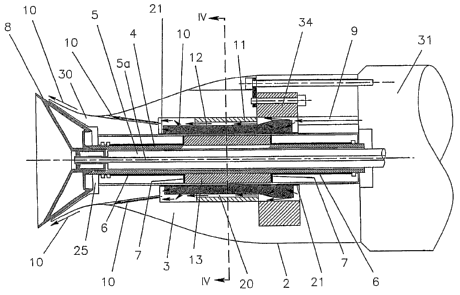
In Figure 2, 3 designates the spindle housing for a painting spindle,
accommodating a rotating shaft 4, which in turn accommodates a non-rotating
tube 5. The rotating shaft 4 is mounted in the housing 3 by means of two
radial
air bearings 6 and, in the example shown, two axial air bearings 7 and bears
at
one end, the left end in the figure, a frustoconical funnel 8, what is known
as a
painting bell, which rotates together with the shaft 4. The stationary tube 5,
which via a duct 5 a conducts paint towards the funnel 8, opens at the end of
the rotating shaft 4 and inside the bell 8, as can be seen from the figure.
Today,
the shaft 4 normally rotates at between 6 000 and 130 000 rpm. 9 designates
air ducts arranged in the spindle housing, which generate a shaping airflow
10,
which causes the paint particles thrown out of the bell 8 during its rotation
to
deviate in the axial direction towards the object (not shown) to be painted.
The
object has earth potential and the spindle with the paint particles has a
voltage
potential relative to the object, lying in the range of 30 000 to 130 000
volts,
which means that the paint particles are attracted by the obj'ect to be
painted.
The shaft 4 is driven by an electric motor consisting of stator iron 11,
stator
winding 12 and a rotor 13 fixed to the shaft 4. What has been described so far
belongs to the known art and should therefore not require further explanation.
Apart from mains connection via a safety transformer, which creates the
necessary electrical separation between the different potential levels (30 000
to
130 000 volts), it is also possible to use energy-storing or energy-generating
units such as, for example, batteries, capacitors or fuel cells, electrically
CA 02567522 2006-11-15
WO 2005/110619 PCT/SE2005/000728
separated from the object to be painted, as the energy source for the electric
motor.
Mounting of the painting bell on the spindle shaft
5
Figure 3B shows in section the rotating spindle shaft 4 with the paint tube 5
fixed therein. 14 designates a part-cone-shaped surface of the spindle shaft
4,
and 15 designates an internal thread of the shaft. The painting bell 8 also
has a
part-cone-shaped surface 16, which interacts with the part-cone-shaped surface
14, and an external thread 17, which interacts with the thread 15 of the
spindle
shaft.
In order to prevent the painting bell 8 accidentally coming loose from the
spindle shaft 4 at high rotational speeds, the threaded part 17 of the
painting
bell 8 has in accordance with the present invention been provided with axial
slots 18 forming segments 19, six segments in the case shown. This means
that, when the painting bell is screwed firmly onto the shaft 4, the threaded
segments 19 of the bell 8 will yield radially inwards against the threads and
the
thread flanks on the threaded part 15 of the shaft 4, which means that, when
the shaft 4 rotates, the segments 19 will on account of the centrifugal force
be
forced outwards or expand and the segments 19 of the painting bell 8 will
generate a radially outwardly directed force, which is in turn transmitted to
the
thread flanks interacting between the spindle shaft 4 and the bell 8, which
also
means that an axial force is produced which causes the part-cone-shaped
surfaces 14 and 16 to "lock" on one another.
The expansion owing to the centrifugal force on the threaded segments 19 will
thus lock the painting bell 8 firmly on the shaft 4 and prevent the painting
bell
8 coming loose during operation. The resilient properties of the threaded
segments 19 will also ensure that the painting bell 8 is guided into locked
position by the cone 16 and 14 and not by the threads 15, 17, which reduces
the tolerance requirements between the respective cone and thread of both the
painting bell 8 and the spindle shaft 4.
Cooling of the stator according to the invention
CA 02567522 2006-11-15
WO 2005/110619 PCT/SE2005/000728
6
When an electric motor 11, 12, 13 (see Figure 2) is used as the drive source
for
the spindle shaft 4, heat loss arises in the stator iron 11, stator winding 12
and
rotor 13 of the motor in addition to the heat produced by the friction losses.
So
as not to risk the functioning of the spindle shaft 4, for example owing to
excessive heating and thus expansion which cannot be handled, it is necessary
to dissipate a sufficiently large part of the heat loss arising, that is to
cool the
spindle 4.
This takes place by the excess heat being carried off with the aid of the
compressed air intended for the shaping airflow 10 and supplied to the
arrangement. This compressed air, or at least part of it, is introduced
according
to the example shown in Figure 2 through one or more ducts 9 in the housing 3
in contact with the stator winding 12 of the electric motor. The figure shows
with the aid of arrows the compressed air passing through the stator winding
12 in ducts 20 next to this. -
Figure 4 shows a cross section IV-IV through the stator in Figure 2, in which
the windings of the latter are designated by 12. These windings are provided
with adjacent through-ducts 20 for the passage of the compressed air (the
shaping air) through the stator and are arranged, according to this figure, on
that side of the windings which faces away from the rotor 13; ducts 20 can of
course be positioned on the inside of the winding or between the winding
wires in the respective winding grooves in the stator. In this way, effective
cooling of the stator and also partial cooling of the rotor are achieved.
However, in order that the cooling air does not leak out to the gap between
the
rotor and the stator, the stator is covered by a leakage-preventing lining 21
(see
Figures 2 and 4).
The shaping airflow 10 leaves the ducts 20 in the stator 11 between its
winding
ends, indicated by the arrows at the ends of the stator winding 12 in Figure
2.
Rotational fixing of the spindle shaft in relation to the spindle housing
without undefined radial loads arising
One problem is demounting (or mounting) the painting bell 8 (see Figures 2,
15-17) from (on) the spindle shaft 4 without damaging the bearings 6 of the
CA 02567522 2006-11-15
WO 2005/110619 PCT/SE2005/000728
7
latter in the spindle housing 3. The bell 8 is normally screwed onto the
spindle
shaft 4, for which reason a torque is required for demounting and mounting the
bell, which means that a counter-torque must be applied to the spindle shaft.
This counter-torque is brought about today by virtue of a torque arm - a pin -
being provided in the spindle shaft, normally at its end facing away from the
bell, which pin is used manually or with the aid of a stop as a stay. This
means
that, when the torque for demounting and mounting is applied, the spindle
shaft 4 will be subjected to a radial force during this work, which leads to
the
spindle shaft 4 being supported in an uncontrolled way against the bearing
surfaces with uncontrolled bearing loads, which can thus cause damage to the
bearings.
Figures 15-17 show an arrangement where the bearing surfaces will not be
radially loaded in an uncontrolled way by the spindle shaft 4 when the torque
for demounting or mounting the bell 8 is applied, as the arrangement is
designed in such a way that the counter-torque is transmitted to the spindle
housing 3 with free translation of the spindle shaft 4 in the radial plane X-Y
being allowed but rotation of the spindle shaft 4 relative to the spindle
housing
3 being prevented.
The said arrangement comprises a locking washer 53 in the form of a ring, the
inside diameter of which is slightly larger than the outside diameter of the
spindle shaft 4. The locking washer 53 is provided with a first pair of inner,
diametrally opposite driving pins 54 and also a pair of second driving pins 55
directed outwardly diametrally in relation to one another, which are arranged
at
right angles to the driving pins 54. The end of the spindle shaft 4 is
provided
with a number of grooves 56 (eight grooves are provided in the example
shown in the figure). The grooves 56 are dimensioned in such a way that they
can accommodate the driving pins 54, while the second driving pins 55 are
accommodated in grooves 57 in the spindle housing 3. The locking washer 53
is limitedly movable in the axial direction in relation to the spindle shaft 4
in
such a away that the driving pins 54 can be brought into and out of
engagement in the grooves 56 while the driving pins 55 are displaced in the
grooves 57 (cf. Figures 16 and 17). Arranged axially outside the locking
washer 53 is a yoke 58 extending in a semicircular shape (for clarity, the
yoke
58 is not sectioned in Figures 16 and 17), which is likewise limitedly movable
CA 02567522 2006-11-15
WO 2005/110619 PCT/SE2005/000728
8
in the axial direction. The free ends of the yoke 58 engage on the outside of
the
locking washer 53 and, according to the example shown, on top of the second
driving pins 55. With the aid of the yoke 58, the locking washer 53 can thus
be
moved axially between a position (see Figure 16) in which the locking washer
53 is, by springs 59 recessed in the spindle housing 3, held displaced in such
a
way that the driving pins 54 are out of engagement with the spindle shaft and
a
second position (see Figure 17) in which the locking washer 53 is, counter to
the action of the springs 59, held pressed down with the driving pins 54 and
55
in engagement with the grooves 56 of the spindle shaft and respectively the
grooves 57 of the spindle housing 3. The yoke 58 is operated with the aid of
an
operating means 61, which can be displaced axially counter to a spring 60. The
operating means 61 is provided with an inclined or wedge-shaped surface 62,
which engages under the yoke 58, suitably under a heel 63 indicated in Figures
16 and 17. When the operating means 61 is held by the spring 60 in the
guided-out position according to Figure 16, the locking washer 53 is guided
out by the springs 59 into the position in which the driving pins are free of
the
grooves in the spindle shaft. By pressing the operating means 61 in counter to
the force of the spring 60, the hee163 will be pressed upwards at the same
time
as the yoke 58 pivots around a stay 64 of the spindle housing, which stay
leads
to the yoke 58 acting as a lever, with the fulcrum in the stay 64, and thus
pressing the locking washer 53 down, so that the driving pins 54 engage in the
grooves 56. The spindle shaft is thus prevented from rotating relative to the
spindle housing but can move freely in the radial direction. If the operating
means 61 is released, this is pushed out, and the yoke with the locking washer
53 is guided by the force of the springs 59 out of engagement with the said
grooves. The outwardly directed movement of the operating means 61 is of
course limited in a suitable way.
Protecting the outlet of radial bearings from being contaminated by paint
A major problem today is that paint accumulates on the spindle shaft 4 (see
Figures 2, 5, 6) at one or both radial air bearings 6, 6. After a time, this
results
in the air acting in the radial bearing being prevented from freely leaving
the
bearing gap, which has a negative effect on the loading capacity of the
bearing
and also cooling, reducing the functioning and life of the painting spindle 2
in
a decisive way.
CA 02567522 2006-11-15
WO 2005/110619 PCT/SE2005/000728
9
In order to prevent this accumulation of paint on the spindle shaft 4, which
disrupts the functioning of the front and/or rear radial air bearings 6, a
chamber 22 is arranged immediately outside the bearing or bearings and
adjacent to the bearing gap, which chamber runs all around and is open with a
gap 23 towards the spindle shaft 4. The bearing air, which operates with
positive pressure and leaves the bearing gap and flows into the chamber 22,
forms a certain positive pressure therein, which leads to a small part of the
bearing air acting as barrier air and flowing out into the gap between the
spindle shaft 4 and the lip running around it between the chamber 22 and a
space 25, preventing paint from entering the chamber, while the greater part
of
the bearing air is carried off from the chamber in a conventional way (not
shown), which avoids a detrimental counterpressure arising in the bearings.
It is also conceivable to arrange an additional, second chamber 26 outside the
chamber 22 shown, as illustrated in Fig. 6. Protective air is supplied to the
chamber 26 with a positive pressure. This protective air is drained on the one
hand to the chamber 22 and on the other hand to the space 25 (duct for air
supply of protective air to the chamber 26 is not shown).
In the embodiment where the spindle housing is extended and surrounds the
painting bell and a gap is formed between the outer periphery of the painting
bell and the spindle housing (see Figure 6), separate extra ducts (not shown)
can lead to the space 25 in order for it to be possible to bring about a
desired
pressure in the space 25.
Surface treatment of the spindle shaft
A different way from that described above, or a complement to it, for
preventing paint adhering and accumulating on the spindle shaft 4 (see Figure
2) adjacent to one or both radial air bearings 6 is for the spindle shaft 4 to
be
coated at least on part of its axial extent with a surface coating, which
reduces
the possibility of the paint adhering to the spindle shaft; otherwise, the
outflow
of the bearing air from the bearings 6 is affected, which reduces the loading
capacity of the bearings and also their cooling.
CA 02567522 2006-11-15
WO 2005/110619 PCT/SE2005/000728
An example of a surface coating is Teflon .
Controlling the shaping airflow (Figures 7, 8 and 9)
5 As mentioned above, the shaping airflow 10 is supplied at high speed
essentially axially towards the painting bell 8 in order, in interaction with
the
electrostatic force, to deflect the paint particles thrown out by the bell
towards
the object to be painted. The function of the shaping airflow 10 of deflecting
the paint particles towards the object is not entirely effective, but a
certain
10 turbulence occurs outside the bell 8 when the shaping air flows out on its
outside and draws the surrounding air along with it, a turbulence which has a
tendency to draw paint particles along with it as well, which can then settle
on
the outside of the arrangement. This is indicated by arrows 27 in Figure 7.
In order to prevent this inconvenience, which occurs in today's painting
spindles, a guide vane means 28 (Figures 8 and 9) is provided, which extends
on the outside of the painting spindle 2 and adjacent to the bell 8 and the
outlets 9 of the shaping air 10 (cf. Fig. 6 also) from the arrangement. The
guide vane means, which is shown as an example in Figure 8, guides the
surrounding air drawn along by the shaping air 10 in an essentially laminar
airflow over the bell 8, by virtue of which the turbulence 27 (Fig. 7)
adjacent
to the outside of the bell 8 is moderated or eliminated. The guide vane means
28 can have the shape of a "ring" running all around or be divided into a
number of sections. 29 designates support flanges for the guide vane means
28, which can suitably be two or more in number. The guide vane means 28
with its support flanges 29 is mounted on and demounted from the spindle
housing 3 in the axial direction, the support flanges 29 being snapped firmly
on the spindle housing 3 in the recesses which are present in connection with
the mounting screws (not shown) of the spindle.
Figure 9 shows an embodiment where a filler 30 is arranged as an integrated
extension of the spindle housing 3 extending over the periphery of the bell 8,
by virtue of which a more even flow of the air drawn along by the shaping
airflow is obtained at the transition from housing to bell in comparison with
the embodiment according to Figure 8.
CA 02567522 2006-11-15
WO 2005/110619 PCT/SE2005/000728
11
In the figures, 31 designates an attachment for the painting spindle. The
filler
30 has an outer form which is suitably shaped to follow the inside of the
guide
vane means 28.
Arrangement of axial air bearings
In order to achieve a painting spindle and thus painting equipment which is as
short and compact as possible, which is of great importance for facilitating
its
use, the positioning of the usually two axial air bearings is of great
importance.
In this connection, an optimal solution is to arrange the two axial air
bearings 7
(see Figure 2) on respective sides of and adjacent to the rotor 13 on the
spindle
shaft 4. At the same time as the installation of the axial bearings 7 is
compact,
the rotor will offer a natural support for the axial air bearings in the axial
direction. Special installation measures for the axial air bearings, which
extend
the spindle shaft 4, are not necessary.
Use can be made of single-acting axial bearings, where the axial force in the
opposite direction is brought about by a magnetic field (embodiment not
shown). When the axial air bearing is not functioning, the surface against
which the shaft is pressed by the magnetic field can be used as a friction
surface in order to brake the rotation of the spindle shaft.
Coding of painting spindle
The practice of using pirate components together with an original product is
becoming increasingly common. This is dangerous in some cases and can have
devastating consequences if the pirate component does not have the quality
(dimensions, material selection etc.) which is required of an original
product.
In order to prevent the use of a pirate-manufactured painting spindle 2 (see
Figure 2), for example in the event of exchanging an original spindle of an
original arrangement according to the invention, it is proposed that the
painting
spindles manufactured are provided with a code, which is read by the control
equipment of the arrangement and makes it possible for only a correctly coded
painting spindle 2 to be used in the original aiTangement. The absence of a
CA 02567522 2006-11-15
WO 2005/110619 PCT/SE2005/000728
12
code or an incorrect code leads to the control equipment of the painting
spindle
responding and making the arrangement unusable, for example by
disconnecting the power supply of the electric motor.
By coding the painting spindle, it is also possible to track and collect data
during operation of the arrangement and to obtain basic information from this
data in order to be able to increase the reliability and performance of the
product. This can take place, for example, by each individual painting spindle
being identified via a control system included in the arrangement and data
being sent to a spindle-monitoring system at the supplier's, in which way
historical operating data for this individual spindle can be collected.
Speed control of the spindle (see Figures 10, 11, 12)
A painting spindle of the kind referred to here driven by an electric motor is
normally carried at the outer end of the arm of a painting robot, as shown in
Figure 1. In view of the rapid movement sequence of the robot arm and
associated torques and loads on the robot, efforts are made to minimize the
weight of the painting spindle 2.
In Fig. 12, 32 designates a power source with alternating current, the
frequency of which is variable. The alternating current fed from the power
source 32 is conducted to a safety transformer 33, where the alternating
current
is converted to low-tension direct current, for example 40 V, which direct
current will contain a superposed frequency which is proportional to the
frequency with which the motor is to be speed-controlled. This frequency is
detected by control electronics 34 (see also Figures 13, 14) integrated in the
painting spindle, where the direct current is, using the superposed
alternating
voltage, converted to the desired feed frequency which causes the electric
motor (11, 12, 13) of the painting spindle (see Figure 2) to rotate at the
desired
speed.
The advantage of connecting the safety transformer 33 to the power supply
before the control unit 34 is that the safety transformer 33 can be allowed to
operate at a considerably higher frequency than that desired for the motor.
This
in turn means that the transformer can be made compact, that is with smaller
CA 02567522 2006-11-15
WO 2005/110619 PCT/SE2005/000728
13
volume and lower weight, as it is desirable, as can be seen from Figure 11, to
position the safety transformer 33 in the robot arm. It is of course also
possible
to combine the transformer 33 and the control unit 34 to form a single unit if
so desired.
Information exchange between the power source and the motor control, in
order to bring about the desired operating characteristics, such as
acceleration,
deceleration and speed, takes place by communication with units connected to
the primary or secondary side of the transformer via information transmitted
via light, sound, radio communication or information in the energy transmitted
or a combination thereof. The rotational speed can for example be read
optically or via sound impulses, which can be used without the requirement for
electrical insulation being affected.
The safety transformer 33 is suitably fed with an alternating voltage, the
frequency of which is a multiple of the desired speed of the spindle shaft 4,
for
example 12-9 times the speed. By virtue of this, it is possible to minimize
the
physical size and weight of the transformer. The alternating voltage received
in
the control electronics (indicated by reference 34 in Figure 12) is to have a
frequency which is a factor lower than the frequency with which the safety
transformer 33 is fed in order to constitute the desired frequency in order to
drive the spindle shaft 4 at the desired speed. By varying the frequency of
the
alternating current fed from the power source 32 to the safety transformer 33,
the speed of the spindle shaft 4 can thus be changed.
Figure 10 shows diagrammatically a configuration which, in contrast to what is
shown in Figure 12, has the control electronics 35 and the power supply unit
32 positioned alongside the robot while the three safety transformers 33 are
positioned in the robot arm and will in this embodiment operate with the
desired frequency of the motor and thus be considerably heavier.
Figure 12 shows an embodiment in which the control electronics 34 are built
into the actual housing of the painting spindle 2. The power source 32 shown
in the figure and the safety transformer 33 can of course be combined to form
a unit.
CA 02567522 2006-11-15
WO 2005/110619 PCT/SE2005/000728
14
Use of connection means for electricity connection
A painting spindle driven by an electric motor requires for its functioning
both
electricity connections for operation of the motor (usually 3-phase and thus
three connections; in the case of control electronics integrated in the
spindle,
two connections are required for direct current) and connections for on the
one
hand cooling air and on the other hand shaping air. In addition, bolts are
required for mounting the painting spindle at the end of a robot arm. In the
case of three mounting bolts, it is therefore necessary for reconditioning or
exchanging the painting spindle to handle three electricity connections, one
cable for control information, two air connections and three bolt connections.
These eight mutually different connections involve unnecessarily time-
consuming work in the demounting and mounting of the painting spindle from
and on a robot arm. The intention is therefore to reduce the number of
connections and to have the mounting bolts also serve as electricity
connections or the air connections also serve as electricity connections or a
combination where both mounting bolt and air connection can serve as an
electricity connection at the same time.
Figure 13 shows diagrammatically a painting spindle, which, by means of
three mounting bolts 36 (only one shown) for example, is mounted on for
example the end of a robot arm via a mounting flange 31 fixed to the arm. The
mounting flange 31 is provided with a recess 37 for each bolt, in which recess
37 a bronze nut 38 is accommodated, which is electrically separated from the
walls of the recess 37 and thus from the mounting flange 31 by means of an
insulation 39. A mounting screw 36 supported with its head 40 in a shoulder of
the housing 3 of the painting spindle extends in an insulated manner through
the housing 3 and is screwed firmly into the bronze nut 3 8. An electricity
cable
41 (one of the conductors) is electrically connected to the nut 38. In the
drawing, 34 designates diagrammatically the control electronics of the motor,
which receive their power in the example shown by means of an electrically
conductive bridge 42, which is electrically insulated (indicated by reference
designation 44 in Figure 13) from the housing 3 of the painting spindle but
which is electrically conductively secured on the one hand by the head 40 of
the mounting bolt 36 and on the other hand by means of a screw 43, which in
CA 02567522 2006-11-15
WO 2005/110619 PCT/SE2005/000728
the example shown extends through the control electronics 34 and via a thread
connection electrically conductively secures the bridge 42.
If the mounting bolts of the painting spindle 2 are designed in the way
5 described here, it is easy to understand that mounting and demounting of the
painting spindle on and from the mounting flange 31 are effected simply by
merely undoing the bolts 36, as the air connections (not shown) consist of
plane surfaces which close tightly when the spindle is mounted.
10 Figure 14 shows how in a corresponding way an air connection also
constitutes
the electricity connection for the control electronics and motor of the
painting
spindle. The air line in the painting spindle is designated by 45. As
described
in connection with Figure 13, the mounting flange 31 is provided with a recess
37 in this case as well. A first bush 39 is fitted in the recess 37. The bush
39
15 surrounds a first electrically conductive sleeve 46 and insulates it iiorn
the
mounting flange. An electricity cable 47 is electrically connected to this
sleeve
46.
In a corresponding way, a second insulating bush 48, which surrounds a
second electrically conductive sleeve 49, which is electrically connected to
the
control electronics 34 or motor of the painting spindle by means of an
electricity cable 50, is arranged in the housing 3 of the painting spindle.
The air line 45, like the air line 51 connected to the mounting flange 31,
consists of electrically non-conductive hoses for example, which each extend
partly into a hole passing through the bushes 46, 49, as can be seen from
Figure 14. Between the ends of the hoses 51 and 45 in the bushes 46 and 49,
the through-hole of the bushes has a smaller diameter, which corresponds to
the inside diameter of the hoses, and the bushes 46 and 49 themselves thus
form a part of the air line. A sealing ring, which prevents air leakage, is
arranged, around the hole formed, between the conductive contact surfaces of
the bushes 46 and 49.
It can be seen from this that as soon as the painting spindle has been mounted
on the mounting flange 31, simultaneous connection of the painting spindle to
air and electricity is automatically achieved.