Note: Descriptions are shown in the official language in which they were submitted.
CA 02567559 2006-10-03
PORTABLE WATER PURIFICATION SYSTEM
FIELD OF THE INVENTION
The present invention relates to a portable water purification system and
more particularly relates to a water purification system including a micro
filtration
device for mechanical removal of cysts and the like, and in addition, a batch
treatment
tank for chemical batch treatment of the water for disinfection, in which the
system is
portable in a transportable container.
BACKGROUND
It is known to provide water purification systems to improve the quality of
water prior to drinking or for various other domestic uses. Water purification
is
commonly required in remote areas for temporary usage and accordingly
transportable water purification systems are also known. An example of a
required
use for a water purification system includes emergency and/or post-disaster
conditions where no electricity or technical support are typically available.
Various examples of water purifications systems are provided in US
patents: 6,616,839 to Peterson et al.; 6,764,595 to Halemba et al.; 5,972,216
to
Acernese et al.; 6,936,176 to Greene III et al.; 4,659,460 to Muller et al.;
5,399,260 to
Eldredge et al.; 6,464,884 to Gadgil; and 5,004,535 to Bosko et al.
In general many known water purification systems are too large to be
manually transportable. Alternatively, smaller portable systems typically do
not
sufficiently purify the water to be fully safe for drinking, do not purify the
water in
sufficient volumes, or require unavailable electricity or unavailable
technical support
and are thus limited in their use. Furthermore, many water purification
systems, large
or small, commonly provide no form of residual disinfectant such as the
addition of
chlorine, or only provide minimal filtration of larger particles due to the
limited number
CA 02567559 2006-10-03
2
of mechanical filtering stages in known portable systems so that the known
systems
cannot ensure removal of all of the possible cysts, viruses and bacteria from
a raw
water supply.
Reverse osmosis is one known example of filtering water to remove
micro particles including cysts and the like, however the volume of water
produced is
very limited as compared to the size of the unit and there is no residual
disinfectant
effect. When no disinfectant is added with no residual effect, the water can
be easily
re-contaminated if stored.
Some portable systems make use of a continuous flow of chlorine
addition, however without a batch treatment tank which stores the water
subsequent
to the addition of chlorine, the chlorine or other disinfectant has to be
added in much
larger volumes to thoroughly mix with the water and disinfect the water
sufficiently to
be safe for drinking. The large addition of chlorine or other disinfectant is
more costly
and may have other detrimental effects to persons consuming the treated water.
SUMMARY OF THE INVENTION
According to one aspect of the invention there is provided a portable
water purification system comprising:
a portable container comprising a hollow interior surrounded by walls
and an opening in the walls which is operable between an open position
arranged to
provide access to the hollow interior through the opening and a closed
position in
which the hollow interior is substantially enclosed by the walls;
an intake arranged for communication with a source of water;
a micro-particle filtration device having an inlet and an outlet and being
arranged for communication of the inlet with the intake for mechanically
filtering the
water from the source of water;
CA 02567559 2006-10-03
3
a support structure arranged to support the micro-particle filtration
device thereon, the support structure being operable between a stored position
in
which the support structure is receivable within the hollow interior of the
container and
a usable position in which the support structure is extended in relation to
the stored
position and is arranged to suspend the filtration device therefrom;
a portable batch treatment tank for communication with the outlet of the
filtration device so as to be arranged for batch chemical treatment of the
mechanically
filtered water from the filtration device in the batch treatment tank; and
a pump arranged to pump the water from the intake, through the particle
filtration device, and into the batch treatment tank.
By providing a system including both microfiltration for mechanically
removing cysts and a batch treatment tank for chemically treating batches of
water in
storage for an elapsed period of time, water from various sources can be
safely
purified regardless of the presence of cysts, viruses or bacteria and the like
in the raw
water, with minimal chlorine addition being required and a resulting residual
disinfectant effect being achieved. Providing such a system with both a
microfiltration
device and a batch treatment tank is particularly advantageous when provided
in a
manually transportable container so that persons can manually handle and
transport
the device into various remote areas where temporary supplies of purified
drinking
water are commonly required. Possible uses can include emergency or post-
disaster
situations where no electricity or technical support is available due to the
simplicity of
the present system which only requires fuel to operate internal combustion
engine
driven pumps to produce potable water.
Preferably the batch treatment tank is expandable from a stored
position, in which the batch treatment tank is receivable within the hollow
interior of
CA 02567559 2006-10-03
4
the container, to a usable position, in which the batch treatment tank has a
volume
which is plural times a volume of the batch treatment tank in the stored
position. The
batch treatment tank may also have a volume which is plural times a volume of
the
container in the stored position.
In some embodiments, the support structure is mounted integrally on the
container and suspends the filtration device therefrom for movement of the
filtration
device with the support structure between the stored position within the
hollow interior
and the usable position in which the filtration device is raised in relation
to the stored
position to extend through the opening.
The container may comprise rigid walls and a lid which is movable
relative to the opening for operation between the open and closed positions.
In this
instance, the support structure may integrally mount the filtration device on
the lid of
the container such that the filtration device is movable with the lid between
the closed
position of the lid, in which the support structure is in the stored position,
and the open
of the lid, in which the support structure is in the usable position.
The lid may be supported spaced above the walls of the container in the
open position by upright legs, the legs being collapsible and receivable
within the
hollow interior of the container in the closed position of the lid.
When the container is elongate in a longitudinal direction between
opposed ends, the filtration device comprises a plurality of filters supported
by the
support structure integrally on the container at the opposing ends and
defining a
storage area therebetween.
The batch treatment tank may be arranged to be supported remotely
and spaced apart from the container in use.
When the container comprises rigid walls and a lid and when there is
CA 02567559 2006-10-03
provided an inlet conduit for connecting the intake to the inlet of the
filtration device
and an outlet conduit for connecting the outlet of the filtration device to
the batch
treatment tank, the inlet conduit and the outlet conduit are preferably
supported to
extend through the lid by respective ports integrally formed on the lid.
5 The filtration device may be operable within the hollow interior of the
container with the lid in the closed position.
When gauges for monitoring a pressure condition of the filtration device
are provided, the gauges may be integrally supported on the container and
readable
from an exterior of the container.
The intake preferably includes a micro filtration cover or micro filter
thereon.
There may be provided a flow restrictor coupled in series with the inlet of
the filtration device which prevents flow into the filtration device above a
prescribed
upper flow limit of the filtration device.
Preferably the portable container is manually portable and includes
handles formed integrally thereon for gripping with a hand of a person.
There may be provided a distribution system including a distribution
manifold, a distribution hose for connection from the batch treatment tank to
the
distribution manifold, and a plurality of distribution valves controlling
distribution of
water through the manifold in which the distribution system is receivable in
the hollow
interior of the container when the container is in the closed position.
When there is provided an inlet hose for communication between the
intake and the filtration device, an outlet hose for communication between the
filtration
device and the batch treatment tank and a distribution hose for communication
from
the batch treatment tank to a distribution manifold, the intake, the hoses,
the
CA 02567559 2006-10-03
6
distribution manifold and the batch treatment tank are preferabiy receivable
in a
storage area defined between integrally supported filters of the filtration
device within
the hollow interior of the container in the closed position of the lid.
The filtration device may comprise an inlet manifold arranged for
communication with the intake, an outlet manifold arranged for communication
with
the batch treatment tank, and a plurality of flow paths communicating between
the
inlet manifold and the outlet manifold in parallel with one another, each flow
path
comprising a plurality of filter members in series with one another.
Preferably, the filtration device comprises at least one disposable filter
member and at least one reusable filter member, the filter members being
supported
in series with one another.
In some embodiments, the container comprises walls of flexible material
arranged to support the filtration device and the support structure within the
hollow
interior of the container in the closed position.
The support structure may be arranged to support the filtration device
remotely and spaced apart from the container in the usable position.
The filtration device may be non-electrical with the pump being driven by
an internal combustion engine, supported on a transportable housing separate
from
the container.
When there is provided a plurality of batch treatment tanks, each tank is
preferably expandable from a stored position, in which the batch treatment
tank is
receivable within the hollow interior of the container in the closed position
of the lid, to
a usable position, in which the batch treatment tank has a volume which is
plural
times a volume of the container.
When the filtration device comprises a plurality of filters coupled
CA 02567559 2006-10-03
7
consecutively in series, each filter preferably restricts passage of smaller
particles
than a previous one of the filters.
The filtration device is preferably arranged to filter particles in stages
down to 1 micron absolute.
One embodiment of the invention will now be described in conjunction
with the accompanying drawings in which:
BRIEF DESCRIPTION OF THE DRAWINGS
Figure 1A is an exploded perspective view of the components of the
water purification system and Figure 1 B is a partially assembled perspective
view of
the container.
Figure 2 and Figure 3 are respective front and rear elevational views of
the container in a closed position.
Figure 4 is a front elevational view in an open position of the container.
Figure 5 is a schematic view of various components of the system
shown connected in use.
Figure 6 is a sectional view along the line 6-6 of Figure 2.
Figure 7 is a sectional view along the line 7-7 of Figure 4.
Figure 8 is a sectional view along the line 6-6 of Figure 2 with the
system in operation in a closed position of the container.
Figure 9 is a sectional view along the line 7-7 of Figure 4 in which the
system is in operation in an open position of the container.
Figure 10 is a bottom plan view of the filtration device supported
integrally on the bottom of the lid of the container.
Figure 11 is a side elevational view of the intake in use.
Figure 12 is an exploded view of the intake.
CA 02567559 2006-10-03
8
Figure 13 is a perspective view of the batch treatment tank.
Figure 14 is a top plan view of the batch treatment tank in use.
Figure 15 is a perspective view of the lid and the particle filtration device
suspended thereon by the support structure according to a further embodiment
of the
present invention.
Figure 16 is a bottom plan view of a lid supporting an alternate
embodiment of the micro-particle filtration device.
Figure 17 is a schematic illustration of a further embodiment of the
portable water purification system.
Figure 18 is a perspective view of the support structure and the micro-
particle filtration device supported thereon according to the embodiment of
Figure 17.
Figures 19, 20 and 21 are respective side elevation, front elevational
and top plan views of the support structure according to the embodiment of
Figure 17.
In the drawings like characters of reference indicate corresponding parts
in the different figures.
DETAILED DESCRIPTION
Referring to the accompanying figures there is illustrated a water
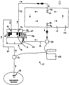
purification system generally indicated by reference numeral 10. The system 10
is
readily transportable and includes both a microparticle filtration device for
mechanically removing microparticies from the water and a batch treatment tank
14
for batch chemical treatment to disinfect the water stored therein in batches
for an
elapsed period of time. For transport, the particle filtration device 12 and
the batch
treatment tank 14, and all required hoses, fittings, etc, are supported within
a
transportable container 16 which integrally supports the filtration device 12
in use and
receives both the filtration device and the batch treatment tank 14 in storage
and for
CA 02567559 2006-10-03
9
transport.
The overall system includes an intake 18 for placement within a source
of water 20 which may comprise untreated water sources including but not
limited to
lakes, rivers, creeks, streams, swamps, swimming pools, fire hydrants or
tanker trucks
and the like. An inlet hose 20 communicates between the intake 18 and the
microparticle filtration device 12 at an inlet thereof for first mechanically
filtering the
water at the intake 18 then again at the filtration device 12. The filtration
device 12
remains supported within the container 16 in use, but the batch treatment tank
14 is
located remotely from the container in use as it is expandable to a size which
is plural
times that of the container for treating large batches of water therein. An
outlet hose
22 is coupled from an outlet of the fiitration device 12 into an inlet of the
batch
treatment tank 14.
The system further includes a distribution hose 24 which communicates
from an outlet of the tank 14 to a suitable distribution area. A raw water
pump 26 is
coupled in series with the inlet hose 20 for drawing water through the intake
18 and
into the inlet of the filtration device. A potable water pump 28 is provide in
series with
the distribution hose for pumping clean water form the tank 14 to the
distributions
area.
Turning now to the container 16 in further detail, the container
comprises a military grade shipping container formed of plastic material which
sealably encloses a hollow interior 34 so that the contents contained within
the
container are weatherproofed from the surrounding environment. The container
includes a bottom wall 30 and side walls 32 which are rectangular and
substantially
surround and enclose the hollow interior 34 of the container. The container
further
includes a top opening 36 which fully spans the top side of the side walls 32
at the top
CA 02567559 2006-10-03
of the container for access to the hollow interior.
A lid 28 is mounted on the walls 32 of the container for movement
between a closed position fully spanning the top opening 36 and an open
position in
which the opening 36 is at least partially unobstructed for access to the
hollow interior.
5 The lid 38 comprises a top wall 40 which is also rectangular in shape and
which
supports a peripheral side flange 42 about a full periphery of the top wall 40
for
extending downwardly to meet the respective side walls 32 of the container in
the
closed position of the lid. The container is elongate in a longitudinal
direction between
opposed ends 44 of the container.
10 The container 16 includes handles 46 formed integrally thereon about
the side flange 42 of the lid and on the side walls 32. The handles are
arranged to be
gripped by two persons with their respective hands so that the overall
container is
manually portable as its typical weight in the stored position is only
approximately
three hundred pounds and therefore manageable by a few persons. To assist in
portability, casters 48 are optionally mounted beneath the bottom wall 30. Two
fork lift
recess channels 50 are also formed in the bottom wall 30 to span laterally
between
the opposing front and rear sides of the container spaced apart from one
another in
the longitudinal direction between the opposed ends 44 by a suitable spacing
for
receiving forks of a fork lift.
Turning now to the intake 18, the intake comprises a base flange 52
which is annular and generally planar for surrounding and spanning radially
outward
from an inlet opening centrally located in the base flange. The diameter of
the base
flange is much greater than, in the order of plural times, a diameter of the
inlet. The
inlet hose 20 communicates with the inlet on a first side of the base flange
52 while a
strainer body 54 communicates with the opposing side of the inlet. The
strainer body
CA 02567559 2006-10-03
11
54 is centered about the inlet having a diameter which is plural times that of
the inlet
but which is smaller than that of the base flange while also having a length
in an axial
direction of the inlet which is also plural times a diameter of the inlet
while being less
than the diameter of the flange. The larger base flange keeps the suction area
of the
strainer body from directly contacting the bottom of a water source.
The strainer body 54 has a porous surface area which is many times the
cross sectional area of the inlet for greatly reducing the suction force and
flow rate
across the surface area of the strainer in relation to the cross sectional
area of the
inlet. A reusable and/or easily changeable microfiltration member 56 fully
covers the
surface of the strainer body 54 to reduce the size of permissible particles
passing into
the inlet through the strainer body to particles less than 600 microns in
diameter. A
suitable clamp 58 retains the microfiltration member 56 in place on the
strainer body.
With further reference to the container 16, the lid 38 is shown movable
between the closed position spanning the opening and the open position in
which the
lid is suspended spaced above the walls to only partially obstruct the
opening. The lid
is supported in the open position as shown in Figures 4 and 7 by a pair of
legs 60
which can be collapsed for displacement of the lid back into the closed
position. The
legs 60 are centered laterally and supported at opposed longitudinal ends 44
of the
container 16.
A rigid bracket 62 is integrally mounted to a bottom side of the lid 38 at
each opposed end 44 of the container and on the bottom wall 30 at each opposed
end 44 for alignment with the respective bracket 62 on the lid. Each leg 60
thus
comprises a rigid post for mating connection between a respective pair of the
rigid
brackets 62 in a vertical orientation. The ends of the post and the rigid
bracket 62
include mating female and male connectors comprising a socket and a respective
CA 02567559 2006-10-03
12
mating projection received therein. The legs 60 are slidably mated with the
respective
rigid bracket 62 for supporting the lid spaced above the side walls in the
illustrated
open position. To return to the closed position, the legs 60 are removed from
the
respective rigid brackets and placed to be extending in the longitudinal
direction within
the hollow interior of the container for storage.
Both top and bottom connections of the legs include a latch on each
side of the leg to secure the connection. Each leg also includes a pin which
inserts
through the leg and then threads into the case structure to further secure and
add
rigidity to the connection.
The filtration device 12 includes a support structure in the form of
clamping rings which selectively mount various components of the filtration
device 12
integrally on the underside of the lid 38 of the container. The components of
the
filtration device are thus suspended from the lid and moveable with the lid
from a
stored position fully contained within the hollow of the container when the
lid is closed
and a usable position extending through the opening 36 in the container,
spaced
above the stored position in the open position of the lid. The filtration
device 12
generally comprises a plurality of individual filters connected in series with
one
another such that each filter in sequence only permits passage of smaller
particles
than the previous filter, so that spread out over multiple stages the
filtration device 12
is capable of filtering down to a level of one micron absolute without
significant
problems of the filters becoming too readily clogged.
The filtration device 12 includes various components coupled in series
along a flow conduit thereof starting at an inlet port 66 which is integrally
formed
within the side flange 42 on the front side of the lid. The inlet port 66
defines an inlet
conduit through the body of the lid for selective connection of the inlet hose
20 on the
CA 02567559 2006-10-03
13
outer side of the lid to the remaining components of the filtration device
within the
hollow interior of the container. Within the interior of the container, the
filtration device
includes a flow restrictor 68 which restricts flow therethrough beyond an
upper flow
limit prescribed to the filtration device. Flow from the flow restrictor 68 is
fed into a
pressure restrictor 70 which reduces the system pressure to an acceptable
level
below a prescribed upper pressure limit of the system.
Once the flow and pressure of the incoming water have been regulated,
the flow is directed into a first filter 72 comprising a bag filter rated at
200 microns to
permit only particles of this size or smaller to be passed therethrough. A
first pressure
gauge 74 monitors pressure after the first filter 72. The first pressure gauge
74 is
mounted integrally in the flange 42 at the rear side of the lid so as to be
viewable from
an exterior of the container.
After the first pressure gauge 74, flow is directed into a second filter 76
comprising a cartridge style filter to remove smaller size particles as the
filter is rated
at 100 microns to permit only particles of this size or smaller to be passed
therethrough. The first pressure gauge 74 accordingly also monitors pressure
to the
inlet of the second filter 76.
A second pressure gauge 78 is also mounted in the rear side of the
flange 42 of the lid so as to be viewed from the exterior. The second pressure
gauge
is coupled to the flow conduit at the outlet side of the second filter for
monitoring
pressure after the second filter. A flow meter 80 is coupled in series with
the flow
conduit downstream from the second pressure gauge in which the flow meter is
accessible and viewable through an access port 82 also located in the flange
42 of
the rear side of the lid. The flow meter is powered by a long life lithium
battery and
measures the flow of water moving through the system in either litres per
minute or
CA 02567559 2006-10-03
14
gallons per minute before the water is furthered along the flow conduit of the
filtration
device.
Subsequently the flow enters a third filter 84 comprising a multiple stage
cartridge style filter to remove yet smaller size particles before continuing
the flow of
water along the flow conduit. The second pressure gauge 78 accordingly also
monitors pressure to the inlet of the third filter 84.
The third filter includes four stages comprising a 50 micron filter
element, a 25 micron filter element, a 10 micron filter element and
subsequently a 5
micron filter element. Upon exiting the third filter 84, any particles greater
than 5
microns in diameter have accordingly been removed from the flow of water. A
third
pressure gauge 86 is coupled to the flow conduit downstream from the third
filter for
monitoring the pressure after the third filter. The third pressure gauge is
also mounted
integrally in the flange 42 of the lid at the rear side so as be visible from
the exterior of
the container.
A fourth filter 88 is downstream from the third pressure gauge 86 and
accordingly the third pressure gauge also monitors pressure to the inlet of
the fourth
filter. The fourth filter 88 comprises a 1 micron absolute filter designed to
remove cyst
sized particles from the water to effectively remove cysts such as
Cryptosporidium
and giardia before the water is forwarded to a fourth pressure gauge 90. The
fourth
pressure gauge 90 measures the pressure downstream from the fourth filter 88
and is
also integrally mounted in the flange 42 at the rear side of the lid so as to
readable
form the exterior of the container.
The flow conduit is then directed to an outlet port 92 which is integrally
formed in the lid in the flange 42 at the opposing front side of the
container. The
fourth pressure gauge 90 accordingly also monitors pressure at the outlet port
92. The
CA 02567559 2006-10-03
outlet port 92 defines an outlet conduit through the body of the lid which
selectively
connects the outlet hose to the filtration device at an outer side of the
container.
All of the filters noted above are selectively separable from the flow
conduit of the filtration device for replacement and/or cleaning of the filter
elements as
5 required. The flow conduit is also releasably connected to the inlet and
outlet ports
respectively while the inlet and outlet ports are also selectively connectable
to the
respective hoses.
In the preferred embodiment, releasable cam lock type connections are
provided at each selective separation of the flow conduit between the various
10 components of the filtration device 12. The connections are threaded and
not
releasable between each filter, only the hose connection to the inlet or
outlet have
cam lock type connections.
The filters of the filtration device 12 are supported in pairs with the inlet
port 66 and the first and second filters 72 and 76 being supported at one end
of the
15 container while the outlet port 92, the third filter 84 and the forth
filter 88 are all
supported at the longitudinally opposed end 44. A storage area is defined
between
the filter pairs at the opposed end for storing other components of the system
therebetween in the closed position of the container.
The flow conduit communicates between all of the filters about a
perimeter of the lid.
The gauges which are all supported integrally on the lid are all located
on a common side of the body of the container along with the flow meter access
port
so that all of the operating components of the filtration device 12 can be
monitored at
once. The filters and flow conduit all remain integrally supported on the lid
by the
support structure as the lid is displaced between the open and closed
positions and
CA 02567559 2006-10-03
16
the inlet and outlet ports are configured for communicating through the body
of the lid
even when the lid is closed so that the filtration device 12 is fully
operational in the
closed position of the lid.
With reference to the batch treatment tank 14, the system is arranged
for batch chemical treatment of water stored therein. The tank 14 comprises a
large
flexible bladder which can be fully collapsed and folded up for storage to be
receivable within the storage area in the hollow interior of the container
when the lid is
closed while also being expandable in use to have a volume which is plural
times the
volume of the container. Multiple bladders may be provided for increasing the
operating capacity of the system.
The batch treatment tank includes an inlet port 94 for connection to the
outlet hose from the filtration device and an outlet port 96 for communication
to the
distribution hose of the distribution system. A testing port 98 is provided
for permitting
access to testing equipment into the batch treatment tank while an additional
disinfectant injection port 100 is provided for receiving doses of a
disinfectant, a
chemical treatment, or both when opened. One or more drains 102 are also
provide in
the membrane of the bladder to assist in draining the tank prior to storage.
The distribution system generally comprises a manifold 104 having an
inlet for connection to the distribution hose and a set of four or more
outlets 106
having respective valves thereon for controlling the flow of treated water
therethrough.
The manifold 104 is storable within the storage area in the hollow interior of
the
container in the closed position, and in use can be supported on the exterior
of the
container 16. A plurality of auxiliary hoses may be connected to each of the
outlets
106 of the manifold for use by multiple independent parties performing
different tasks
which require potable water. A check valve is provided in series with the
distribution
CA 02567559 2006-10-03
17
hose to prevent water back flowing into the batch treatment tank 14.
All of the hoses used in the system as noted above are food grade
plastic and have different style connectors at respective ends thereof to
ensure that
each hose can only be connected to a designated one of the ports of the
filtration
device, the batch treatment tank or the distribution system. When in storage,
the
pumps are initially contained in a separate container 108 while the components
of the
distribution system, the collapsed batch treatment tank 14 and the intake,
along with
the respective hoses associated therewith are all received within the storage
area
between the filters at opposed ends 44 of the container, along with the legs
which are
collapsed with the lid in the closed position.
For use, the lid of the container 16 is initially unlatched from the side
walls to permit the lid to be raised and supported spaced above the side walls
by the
legs 60 received in the respective brackets 62. While the filtration device
remains
integrally supported on the underside of the lid of the container by the
respective
supporting structure moveable with the lid, the remaining components are
removed
from the storage area within the hollow interior of the container for
connection such
that the intake is positioned within a source of water, the inlet hose
communicates
from the intake to the inlet port integrally formed in the lid of the
container, the outlet
hose is connected from the outlet port of the filtration device to the inlet
of the bladder
and the distribution hose is coupled from the outlet of the bladder to the
manifold
supported on the container body. Also the pumps are removed from the second
container 108 so that the raw water pump is connected in series with the inlet
hose
and the potable water pump is connected in series with the distribution hose.
The pumps are each driven by respective internal combustion engines
so fuel for the pumps is the only input energy required as there are no
electrical
CA 02567559 2006-10-03
18
components required to operate any of the remaining components of the system.
By
operating the raw water pump, water is collected from the source and forced
through
the filtration device to effectively mechanically filter the water down to one
micron
absolute which is fed into the inlet of the batch treatment tank 14. Solar
powered
electric pumps can optionally be used if desired.
Operation of the raw water pump continues until the bladder is at three
quarters full capacity as monitored by the flow meter of the filtration
device. At this
stage disinfectant tablets in a dosage for a full bladder are added to the
water within
the bladder through the disinfectant inlet port on the batch treatment tank
14. Adding
the disinfecting tablets when the tank 14 is only three quarters full ensures
adequate
circulation of the disinfectant as a result of the remaining water to be
flowed into the
bladder. Once the disinfectant has been added, the raw water pump is continued
to
operate until the tank is at full capacity as monitored by the flow meter.
The water within the batch treatment tank is then stored for
approximately thirty minutes or as otherwise specified by the disinfectant
being added
until the water is bacteriologically safe and ready for distribution. No pumps
are
operated and no flow is permitted during the batch treatment in the tank 14.
Once the elapsed period of time has expired, the potable water pump is
operated as demand of water from the distribution system requires it. Users
can thus
open any of the valves on the manifold to release water at which point potable
water
pump will operate to maintain pressure in the distribution hose.
When multiple tanks 14 are provided, upon completely filling one of the
tanks after disinfectant has been added, a second tank may be immediately
filled by
connection to the outlet hose for overlapping the required batch treatment
duration in
the first tank. Water may then be already ready to be dispensed from the first
batch
CA 02567559 2006-10-03
19
treatment tank during the elapsed period of time for treatment in the second
tank.
Once the treatment period has expired on the second tank, water may instead be
distributed from the second tank while the first tank is refilled on an
ongoing cycle.
Once the system is no longer required, all of the hoses are disconnected
from the respective components and the storage tanks 14 are collapsed and
folded so
that all of the components are stored within the storage area in the hollow
interior of
the container 16 with the exception of the two pumps which are stored in the
second
container 108. The two containers can be easily handled manually by operators
of the
system for transport.
In summary, the system comprises a complete stand alone water
treatment system using advanced microfiltration and chlorination technology in
a
compact, lightweight, flexible, reliable and complete package with a low
capital and
low operating cost. The system produces potable water without the use of
electricity,
gravity or challenging chemicals. The system makes use of technology to remove
cysts such as Giardia and Cryptosporidium and a proven batch treatment tablet
technology that eliminates a wide spectrum of micro-organisms, viruses,
bacteria and
waterborne disease such as e. Coli, faecal coliforms, Cholera, Typhoid and
Dysentery. All of the components of the system are housed in two compact
military
grade shipping and operating modules and is capable of producing over 35,000
litres
per day of drinking water with no objectionable chemical taste. Raw water is
drawn
through the strainer body of the intake and transferred to the microfiltration
system
using the fuel powered pump provided. The advanced microfiltration system
removes
cysts, sediment and turbidity from the water before it travels to the batch
treatment
tank for final treatment. The addition of specialized Sodium
Dichloroisocyanurate,
chlorine or other disinfectant tablets removes bacteria, viruses and
waterborne
CA 02567559 2006-10-03
disease from the water so that the water is now ready for distribution from
the tank
using a choice of hand or fuel powered pumps and a provided distribution
system.
The system is a complete field ready water purification system which
requires no on-site technical support for setup or operation. The system
includes a
5 dual process to produce bacteriologically safe water by making use of easy
to use
and safe to handle chlorine or other disinfectant based tablets. Liquid
disinfectants
can also be used. An on-site water testing and documentation program and
equipment is provided for further safety. The system is completely reusable
and
storable while being easily transportable by land, sea or air in a system
which can
10 draw raw water from lakes, rivers, swimming pools, fire hydrants and the
like.
The filtration device involves nine levels or stages of microfiltration with
no pre-filtration required in some embodiments, while in other embodiments
described
herein involve only 5 levels or stages of filtration in the filtration device.
In either
instance the filters can be changed quickly and easily including washable and
15 reusable pre-filters. Location of the pressure gauges are easy to read to
monitor
proper operation to ensure that substantially all silt, turbidity and sediment
are
removed to a level of one micron which exceeds NSF standard 53 for cyst sized
particles. Subsequent use of a batch treatment tank including chlorine
tablets, or other
suitable equivalents, protects against recontamination during storage. An on-
site
20 chlorine testing and documentation kit which is included permits quality of
the chlorine
or other disinfectant levels within the water to be monitored.
The bladders forming the batch treatment tanks 14 each a volume of
approximately 5,000 litres and require approximately two hours to fill. Once
full the
purification tablets are allowed to react within the bladder for 30 minutes at
which
point the water is ready to be distributed. Using the potable water pump, the
entire
CA 02567559 2006-10-03
21
bladder can be distributed in approximately 45 minutes. Once the bladder has
been
emptied the cycle is complete and a new batch can be started. The main system
typically only includes one bladder. When using one bladder the system can
produce
35,000 L per day. Alternatively, a second bladder may be provided in which
case the
system can produce 50,000 L when using both bladders.
The system can be easily setup with a minimum number of persons
(typically 2 to open lid and only 1 to operate after that) and no technical
expertise or
support required as all of the hose connections are quick-connect connections
requiring no tools. The initial setup stage involves locating the container on
level
ground and opening the primary container 16 by raising the lid to its open
position
spaced above the walls. All of the components are removed from the container
with
the appropriate connections being made so that raw water can be pumped from
the
source through the filtration device and into the batch treatment tank. Once
the
disinfectant has been added to the tank and the tank has been filled water is
ready to
be distributed within 30 minutes using the provided distribution system.
Distribution
may be effected using the potable water pump in series with the distribution
hose, or
alternatively a back-up foot pump may be provided for manually pumping water
through the distribution system.
The water quality testing kit provided with the system permits every
batch of water produced to be tested for residual levels of free chlorine. The
treatment
and test results can also be documented using the kit provided. Testing takes
less
than 60 seconds and can be done as often as required. A manual test kit
includes a
base chlorine test kit consisting of a thermometer, a sample bottle, free
chlorine test
strips, pH test strips, blank documentation reports and a clipboard. A digital
test kit
includes all of the components of the manual test kit plus a hand held digital
meter
CA 02567559 2006-10-03
22
capable of providing accurate measurements of pH and free chlorine without the
use
of test strips which can be hard to colour code.
An advanced testing module provides a verifiable, reliable and real time
record of water quality parameters including temperature, pH, free chlorine
and
oxidation reduction potential. The module is self-contained, microprocessor
based
and battery powered and serves to indicate water quality. The module attaches
directly to the batch treatment tank via a dedicated testing port providing
constant
data to the user. A data transfer adapter is also available to download
historic data to
a laptop or a personal computer.
When sanitizing water for consumption a strong oxidizer is added at
appropriate levels. The oxidizer disrupts the cells of contaminants in the
water being
treated, rendering the cells dead or no longer a threat to health. As a result
some of
the oxidizer is spent. The remaining or residual oxidizer or sanitizer must be
at
appropriate levels to ensure appropriate remaining oxidizing potential,
therefore when
sanitizing water for consumption, residual oxidizer is important. If the
oxidation
reduction potential is too low, the water just processed might become re-
contaminated, creating a hazard. The advanced testing module circuit detects
the
residual or remaining sanitizer and continually reports its oxidation
reduction potential
or oxidation power to provide the operator assurances that the water is fit to
drink.
The advanced testing module also measures pH. No training is required to
operate
the module and the module also operates without attendants. The module also
maintains a log of pH, disinfectant and temperature and warns of
recontamination.
Ongoing changes in water quality are indicated to guard against contamination
or
unsafe water.
The overall system includes a number of important safety features.
CA 02567559 2006-10-03
23
Different sizes and configurations of hoses are provided to ensure that a raw
water
hose is never mixed up with a treated or finished water hose. Flow restrictors
and
pressure limiters are included within the microfiltration device to ensure
that the filter
manufacturers specifications and guidelines are not exceeded regardless of
pump
size. A digital flow meter ensures that the water bladder is filled accurately
for
precision chlorine dosing. A water quality testing kit ensures that each and
every
batch of water produced is tested for residual chlorine levels and allows for
accurate
chlorine dosing. All hoses have a gasket sealed dust cover to ensure that the
hoses
stay clean and sanitary when in storage within the hollow interior of the
container until
use. In the assembled configuration, all hoses and connections can be secured
in
place with padlocks to prevent tampering. The entire microfiltration system
can be
operated in the closed position of the lid to provide security during
challenging
environmental or social conditions. All hoses and tanks are food grade. All
gas or
diesel pumps are stored in separate cases to prevent cross-contamination of
fuel and
or fuel odours to food grade hoses, tanks, etc.
When the lid of the container is closed, the container measures
approximately 53 inches in the longitudinal direction, 29 inches high and 28.5
inches
wide. The lid is moveable between the open and closed positions with the
microfiltration integrally supported thereon for movement therewith. Support
handles
are provided on all sides of the container for ease of manually transporting
the
container. The container also includes a flush out drain for cleaning and two
way fork
lift pockets extending laterally from a front side to a rear side of the
container. The
auxiliary container for supporting the pumps measures approximately 2 feet by
2 feet
by 2 feet and is arranged for secure stacking with the primary container 16.
The
containers are rotomolded in design and are provided with gasket seals on all
CA 02567559 2006-10-03
24
openings and fittings penetrating the case. The latches which secured the lids
to the
walls of the container are twist type and lockable. A pressure relief valve is
provided
as well.
The overall system is extremely flexible and has a number of valuable
options that can be added or can be custom designed. Additional tanks 14
ranging
from 5,000 litres to 10,000 litres capacity can be added to increase
production and
storage capacity. Collapsible bottles ranging from 6 to 19 litres may also be
provided
for safe storage and transportation of the treated water. Additional filling
lines may
also be provided to increase capacity. Filter replacement packages are also
provided
for maintaining condition of the microfiltration device. Special application
distribution
modules in packages for shower, kitchen or decontamination facilities, for
example,
may be added on to the system 10. Special application filtration modules for
unique
water sources may also be provided.
Among the special modules a heavy metal module may be provided
which will remove and/or reduce a number of contaminates such as mercury,
lead,
VOC's, pesticides, herbicides, etc that may be present in some high risk water
sources. Long term consumption of heavy metals has been linked with a number
of
health concerns.
A hydrocarbon and synthetic oil module may also be provided which
removes all traditional and synthetic oil contamination down to non-detectable
levels.
Shorter term consumption of traditional or synthetic oils can cause various
unpleasant
conditions to users to the water. While most fresh water sources are not
contaminated
with traditional or synthetic oils, emergency situations may dictate the use
of city
harbours or rivers that may indeed be contaminated. Basic hydrocarbon removal
can
now be done by switching out one of the disposable filters within the system
that only
CA 02567559 2006-10-03
filters out particles with a special filter capable of removing both particles
and
hydrocarbons.
The system 10 produces potable drinking water without electricity,
gravity, challenging chemicals or technical support. The system is extremely
compact,
5 portable and lightweight, easily transportable by truck, boat, helicopter or
aircraft. No
electricity or gravity is required. The system is a complete field ready water
purification system in which absolutely everything is included. No on-site
technical
support is required to setup or operate the system. The system involves a dual
process cyst removal and virus and bacteria inactivation using easy to use and
safe to
10 handle chlorine based tablets. Easy to use on-site testing and
documentation is also
provided. The system is shipped in military grade shipping and storage modules
which are easily transportable by land, sea or air. Gas or diesel pumps are
stored
separately to prevent fuel cross contamination.
Because the system 10 does not require electricity to operate, it is
15 lighter with fewer parts prone to failure in the field. Small but reliable
gas or diesel
powered pumps are used instead of electric pumps. Many electric pumps supplied
with other systems are not designed to move water up elevations or over
distances.
The system is available with optional pumps of varying size and power to meet
individual needs.
20 The system is shipped within compact, lightweight, military grade cases
that act as both storage and operating modules. Many cases supplied with other
systems are extremely heavy, awkward, bulky, expensive to ship and hard to
move
around. The containers of the current system 10 are completely sealed with air
tight
gaskets, pressure relief valves, and also meet international insect control
standards
25 that many wooden cases do not.
CA 02567559 2006-10-03
26
The system 10, according to preferred embodiments, incorporates a 5
stage microfiltration system that is designed to work in challenging, real
life
conditions. Most 2 or 3 stage systems are just not practical when the water
source is
the least bit turbid. When the filters of the system 10 do not need to be
changed,
inexpensive filter stages are there to protect the more expensive and
important ones.
The system 10 uses reliable chlorine technology to eliminate bacteria,
viruses and other waterborne diseases and to leave a residual level of free
chlorine to
protect the treated water from recontamination during storage, transportation
and
distribution. Reverse osmosis and UV light systems do not provide this
protection.
Recontamination of treated water is a real threat, especially in the
challenging
conditions that the Can Purees WPS is designed to be used.
The system 10 offers incredible value when compared with reverse
osmosis or UV light-based systems. Factors to consider include: low capital
investment; a typical chemical treatment cost of approximately one cent per 20
L (5
US Gal.); inexpensive pre-filters to protect more expensive filters to reduce
operating
costs; the system 10 being one of the lightest systems available which also
saves
shipping costs; the system 10 does not require technical support which can
often cost
more than the systems themselves; and the system 10 is built to operate under
rugged conditions and to be used and re-deployed over and over again reducing
the
capital investment each and every time it is used.
The system 10 includes a number of safety features that most systems
overlook including: flow restrictors and pressure limiters to ensure that it
is impossible
to accidentally overload the microfiltration system by using a pump that is
too large;
devices, such as a digital flow meter, to ensure the water bladder is not over
or under
CA 02567559 2006-10-03
27
filled and to allow for precision chlorine dosing; check valves and pressure
relief
valves included to protect the investment in pumps and prevent downtime in the
field.
The system 10 offers 3 different field testing programs. These programs
provide the user with the ability to test and document each and every batch of
water
produced. Reverse osmosis and UV light systems simply do not provide this
valuable
feature.
The system 10 uses microfiltration and chemical treatment. Chlorination
without microfiltration is simply not effective. The process of chlorination
to kill
micro-organisms, as discussed by the World Health Organization (WHO), reads
"...the
process only works, however, if the chlorine comes into direct contact with
the
organisms. If the water contains silt, the bacteria can hide inside it and not
be reached
by the chlorine.".
The system 10 provides absolutely everything required to produce, store
and distribute water, free of cysts, bacteria and viruses. No other system
provides
such a complete and comprehensive package including test kits, spare parts,
hose
repair kits, bladder repair kits (that do not require heat sources) and much
more.
Optional equipment includes collapsible water bottles for storage and
distribution from
6 L -20 L, additional water bladders from 5,000 to 10,000 L for extra
versatility, a
multi-line distribution system allowing an unlimited amount of users to fill
bottles at
once, and much more.
The system 10 is a complete, turn-key water purification system capable
of producing over 50,000 L per day of potable water in emergency situations.
The
system 10 ensures the mechanical removal of cysts and the inactivation of
viruses
and bacteria through chemical disinfection. The method of chemical
disinfection also
CA 02567559 2006-10-03
28
provides a means of protecting the produced water from recontamination during
storage, transportation and distribution to end users.
The system 10 contains all equipment, components and manuals
required to treat, store and distribute potable water using fresh water
sources such as
lakes, rivers and streams. The system 10 operates without the need for
electricity or
electrical generators and/or gravity. The system is lightweight and compact in
nature
and easily transportable by no more than 4 people via pickup truck,
helicopter, small
aircraft or small watercraft.
The system 10 is operable by any adult with basic mechanical aptitude
and does not require any outside technical expertise or support to operate,
repair or
maintain. The system 10 includes all components and systems required to
produce
potable water, store up to 10,000 L of said water, and finally bottle said
water into
transportable containers at a minimum rate of 29 gpm. The system 10 also
includes a
complete spare parts kit and repair kit capable of allowing field repairs to
all systems
including pumps, treatment systems, storage systems and distribution systems.
The system 10 also includes a water quality testing kit capable of testing
for pH, temperature, free chlorine and/or ORP with data log and download
capability.
The system 10 is contained in 2 compact, waterproof, durable, military
specification storage and transportation cases. The system is also adaptable
to
customer provided storage and transportation solutions to match current
operating
guidelines and/or systems.
The microfiltration device is designed to mechanically filter raw water
drawn from the raw water source. This filtration removes turbidity, silt,
sediment and
organic matter necessary for effective water disinfection while also removing
cysts
such as Giardia and Cryptosporidium which cannot be effectively inactivated by
CA 02567559 2006-10-03
29
chemical disinfection and which can cause serious gastrointestinal illness.
The
microfiltration device can also be used to remove hydrocarbons such as oil and
gasoline by simply switching out one specific filter. Hydrocarbons are often
present in
flood conditions where vehicles have been submerged or in some municipal
harbors.
The system 10 is designed to be operated in an included
storage/transportation case in order to provide necessary protection from
challenging
environmental and social conditions. The system does not have to be removed
from
its protection storage/transportation case and exposed to the elements in
order to be
operated.
The system includes a 5 stage food grade microfiltration system capable
of producing 12 gpm of filtered water. The pre-filters are washeable to extend
filter
life and the system is capable of 1 micron absolute filtration, that exceeds
the 3 log
99.9 removal requirement described in NSF Standard 53. The system 10 is
capable
of basic hydrocarbon removal without additional assets at a rate of 12 gpm and
is
capable of filtering the following water conditions: flooded surface water
with high
levels of turbidity and organic debris. The system 10 is complete with a
pressure gage
system between all primary filters to measure to a detail of no less than 2
lbs per
square inch increments. The system 10 is complete with safety devices to
prevent
accidental pressure and/or flow overload resulting from substitute pumps, fire
hydrants, etc.
The system 10 is pressure tested before shipment to 60 PSI. The
system 10 is also: complete with all tools required to perform filter changes;
complete
with a sealed system, long life 3 volt lithium battery powered flow meter
operable in
Imperial or metric, pre-calibrated, including reset feature, flow rate per
minute, total
flow rate, and non-resettable cumulative flow history, accuracy +/- 3%,
readability +/-
CA 02567559 2006-10-03
0.1%; operable within an impact resistant protective storage/transportation
case
without removal from said case; contained within mil-spec
storage/transportation case
no greater than 53 x 29 x 29" including 2 way fork lift access, 4 side carry
handles,
emergency drains, waterproof seals and pressure relief valve for air
transport;
5 weighing approximately 375 lbs along with an additional 50 lbs gas pump
module,
weight including the mircofiltration system and the container; adaptable to
customer
supplied case system; and complete with spare parts kit and field repair kit.
The batch treatment tank 14 which comprises a collapsible bladder, is
an integral part of the system. The collapsible bladder is a custom designed
closed
10 system, collapsible storage tank. A closed system storage tank protects the
water
inside from outside contaminants whereas an open top onion style tank does
not.
Each bladder contains custom fittings allowing for separate inlets, outlets,
testing
ports, drains, etc. Each bladder contains safety and isolation devices which
protect
the water during storage from back flow, accidental raw water inflow, etc.
Each
15 bladder includes a ground sheet for added protection when operating on
rough
surfaces. It is critical of course that the bladder be made of food grade
materials.
The tank 14 comprises a standard 5,000 L collapsible food grade
bladder (non-mil-spec) (for daily production 35,000 L) and includes the
following food
grade, camlock fittings, 1 x 2" inlet, 1 x 2"outlet, 1 x 2" testing port, 2"
tablet port and 2
20 x 2" drains. An optional second 5,000 L collapsible bladder, duplicate of
the above,
increases daily production to 50,000 L. The optional second bladder requires
an
additional storage/transportation case. An optional mil-spec bladder can be
made
available as well as an optional 10,000 L bladder with same fittings available
in either
regular or mil-spec food grade materials. Each bladder is complete with a
ground
CA 02567559 2006-10-03
31
sheet and includes safety and isolation devices to isolate water during
storage and
distribution.
After microfiltration, the water is free of cysts but still requires
disinfection to inactivate viruses, bacteria and other waterborne illness
including
E-coli, fecal coliforms, typhoid, cholera, etc. The system's disinfection
tablets produce
measurable amounts of free chlorine, are safe to handle, classified as non-
hazardous,
are safe for long term use (vs. iodine disinfection), and have been proven
through
numerous field trials.
The gas powered centrifigual pumps of the system 10 are reliable, easy
to use, compact and lightweight in nature. The pumps are critical in moving
both raw
water and finished, potable water throughout the system. The pumps include a
pump
protection system that will protect the pump in the event of a sudden blockage
of the
water flowing from the pump. This can happen if a vehicle drives over a hose
line, a
kink develops in a hose or a distribution hose or a valve is shut off without
accompanying pump shut off. Each pump can be clearly marked and fitted with
different fittings in order to prevent the raw water pump and the potable
water pump
from being accidentally switched with each other. The pumps include the
following
specifications: 29 GPM gas powered centrifigual pump with industrial use 2
year
warranty; dry weight: 15 lbs. per pump; complete with pump protection system -
check
valve, pressure relief device to prevent pump damage; 2 units, each to include
different fittings and marked for raw and treated water only respectively;
include 10
and 20 L mil-spec portable fuel containers with gravity flow fuel feed system;
include
field repair kits including: spark plugs, air filter, fuel filter, etc;
complete with mil-spec
storage/transportation case including custom cut foam protection lining.
CA 02567559 2006-10-03
32
The system 10 makes use of specific hoses for specific purposes. Each
hose is food grade rated and of the highest quality. The overall hose design
ensures
that hose diameters and fittings are different to ensure that raw water hoses
and
potable water hoses are never mixed up. Each hose is also labeled with
waterproof,
durable labels that include the hose label and set up instructions.
All hoses are food grade rated. The system 10 includes: 1 suction hose
1" x 25", suction rated, 1 supply hose. 1" x 100', lay flat, 1 supply hose,
3/4" x 50'.
hard line, kink resistant, complete with shut off valve, 1 supply hose, 1" x
50' hard line,
kink resistant, complete with shut off valve and check valve, 1 supply hose,
1" x 50',
hard line, kink resistant, complete with shut off valve and check valve, and 4
distribution hoses, 1/2" x 10', complete with spring loaded nozzles, without
lock open
device. The overall hose design includes a safety system ensuring non-
compatibility
with incorrect system hose placement. Each hose is pressure tested to 60 PSI.
Each
hose is complete with PVC camlock fittings (excluding distribution hoses
complete
with brass quick connect fittings). Each hose includes gasket seal dust covers
excluding the brass fittings.
The distribution manifold is designed to split the supply of potable water
being pumped out of the bladder into 4 sub lines fitted with trigger style,
spring loaded
fittings. These fittings allow a minimum of 4 users at a time to distribute
water,
generally into collapsible 19 L optional containers. The distribution manifold
quickly
and easily attaches to the microfiltration system case which also provides
hangers for
each of the 4 distribution hoses. Construction of the manifold is brass and
PVC.
Fittings are brass quick connect type. The manifold is complete with an
attachment
bracket designed to connect to the container 16 or to a customer supplied
case. The
CA 02567559 2006-10-03
33
manifold comprises a brass, 4 head splitter including individual shut off
valves to split
a supply line from the bladder into 4 individual distribution hoses.
The system 10 includes a complete spare parts kit and field repair kit
having 2 of any and all required gaskets 1 of any and all gasket lubrication,
1 thread
sealing tape, thread sealing liquid, 1 pressure gage, 2 clamps for each size
of hose
supplied, 1 pump repair kit, 2 hose repair menders for each size applicable
hose, 1
hose protective/repair sleeve and 1 pressure gage with a 5 foot spare
connecting line.
The system 10 is a complete turn-key water treatment system that
requires no outside components or support (except gasoline or diesel fuel for
pumps).
The system 10 removes both cysts (by mechanical filtration) and bacteria and
viruses
(by batch treatment chlorination). The system 10 includes water filtration,
purification,
storage and distribution in one package, notably such a small package of only
2
cases. The system 10 is integral to its shipping/storage case. Most systems
have to
be removed from the shipping/storage case to be set up and operated.
The system 10 uses a batch treatment concept where water is filtered
and transferred to a storage tank (bladder) for treatment with chlorine
(requires
contact time) and then is distributed using included pumps.
The distribution system either supplies water to a distribution manifold to
4 or more separate hoses with nozzles for distribution into individual
containers or
transfers water directly to a shower or kitchen trailer.
The intake of the system 10 is unique in that there is provided a micro
filtration member spanning the strainer body. The membrane is a plastic mesh,
600
microns that is adapted from a traditional replacement bag filter to immensely
improve
the ability of the strainer body to filter out particles.
CA 02567559 2006-10-03
34
The addition of a pump protection system to the small, compact gas
powered pumps is an important improvement over the prior art pump
configurations.
Conventional pumps are not protected from sudden stoppages such as a truck
driving
onto a hose and stopping the flow of water, or someone shutting off the nozzle
while
the pump is running.
The filtration device of the system 10 involves a 9 stage microfiltration
system in a compact and unique package including a 600 micron filter stage
right on
intake strainer, one 4 layer filter stage, and additional filters. The whole
system can
filter challenging water (flooded river) and continue to operate. Prior art
systems
commonly only provide 2 filters, 2 stages of filtration and a non-graduated
filter
system, for example raw water fed into a 5 micron filter which causes rapid
filter
plugging. Alternatively, the system 10 takes raw water and sends it through a
600
micron filter, a 200 micron filter, a 100 micron filter, a four stage 50
micron/ 25 micron/
10 micron /5 micron filter and finally a 1 micron absolute filter. Additional
filters can be
added to remove oil and gasoline down to non-detectable levels.
As described above, the system 10 is a complete, turn-key water
purification system capable of producing 35,000 to 50,000 L of potable water
in
emergency situations. The system 10 produces potable water by removing
parasitic
cysts through mechanical filtration and inactivating viruses and bacteria
through
disinfection via chlorination. The method of chemical disinfection also
provides
residual levels of free chlorine to protect the finished water from
recontamination
during storage, transportation and distribution to end users. The system 10
contains
all equipment, components and manuals required to treat, store and distribute
potable
water using fresh water sources such as lakes, rivers and streams. The system
10
operates without the need for electricity, electrical generators and/or
gravity. The
CA 02567559 2006-10-03
system is lightweight and compact in nature and easily transportable by no
more than
4 people via pickup truck, helicopter, small aircraft or small watercraft.
The system 10 is operable by any adult with basic mechanical aptitude
and does not require any outside technical expertise or support to operate,
repair or
5 maintain. The system 10 includes all components and systems required to
produce
potable water, store this water, and finally, dispense this water into
transportable
containers at a minimum rate of 29 gpm. Optional components are available to
supply
kitchen, shower or decontamination facilities. The system 10 also includes a
complete spare parts and repair kit allowing field repairs to all systems
Including
10 pumps, water bladders and distribution systems.
The system 10 also includes a water quality testing kit capable of testing
for pH, temperature, and free chlorine. A variety of optional, advanced kits
are also
available to test for free chlorine, total chlorine, pH and/or ORP with data
log
capability.
15 The system is contained in 2 compact, waterproof, durable, mil-spec
storage and transportation cases. The system is also adaptable to customer
provided
storage and transportation solutions. The cases are rugged, durable, and
designed to
mil-specs, to act as shipping, storage and operating housings. For instance,
the
micro-filtration system is not just stored within the first case, it is
integral supported in
20 the first case. The first case or container 16 includes: 2-way fork lift
pockets, 4-way
carry handles with high and low positions; waterproof gasket seals; a breather
valve;
lockable latches; a stackable design; mil-spec MIL-STD-810, MIL-0150
standards;
optional casters; and does not rust, rot, corrode or require insect
certification like
wood.
CA 02567559 2006-10-03
36
The micro-filtration system is designed to mechanically filter water
drawn from the raw water source to 1 micron absolute. Filtration to this
degree
removes parasitic cysts such as Giardia and Cryptospohdium while also removing
turbidity, silt, sediment and organic matter necessary for effective water
disinfection
using chlorination. The filtration system is integral to the shipping/storage
case itself
and can be operated in either the open or closed position. Operating the
system in the
closed position is ideal during challenging environmental or social
conditions.
The micro-filtration system can also be used to remove hydrocarbons
such as oil and gasoline by simply switching out one specific filter.
Hydrocarbons are
often present in flood conditions where vehicles have been submerged or in
some
municipal harbors. In the preferred embodiment, the micro-filtration system
has 5
stages, including 1 micron absolute technology capable of producing 12 gpm of
water
that exceeds the 3 log 99.9 removal requirements described in NSF Standard 53.
The system has pre-fitters that are washable for extended filter life; is
designed to
work with challenging water sources such as flooded rivers with high levels of
turbidity
and organic debris, etc; is complete with a pressure gauge system to measure
the
differential pressure between filter housings which is waterproof, visible
from the
exterior, has readings to 2 liter per square inch detail; is complete with
advanced
safety devices to prevent accidental pressure and/or volume overload resulting
from
substitute pumps, fire hydrants, etc; is pressure tested before shipment to 60
PSI; is
complete with all tools required to perform filter changes; is complete with a
flow
meter sealed system with a long life, 3 volt lithium battery powered system
operable in
imperial or metric, pre-calibrated, including reset feature, flow rate per
minute, total
flow rate, and cumulative fiow history, with accuracy to+/-3%, readability to
+/-0.1%
and visible to the exterior; is contained within and integral to a compact mil-
spec
CA 02567559 2006-10-03
37
roto-molded storage, transportation case; is adaptable to customer supplied
case
system upon request; and is complete with a spare parts kit and a field repair
kit.
After micro-filtration, the water is free of cysts but still requires
disinfection to inactivate viruses, bacteria and other waterborne illness
including
E-coli, fecal coliforms, typhoid, cholera, etc. The disinfection tablets of
the system 10
produce measurable amounts of free chlorine, are safe to handle, classified as
non-hazardous and are safe for long term use (vs. iodine disinfection). The
tablets
are stored in water resistant tubs in waterproof packaging; classified as non-
hazardous, complete with MSOS and Safe Transport documentation; and have an
active ingredient to NSF/ANSI Standards Active ingredient approvals for
drinking
water use by the US EPA and World Health Organization. Each tub of 60 tablets
measures less than 8 inches by 6 inches and treats 150,000 L of water.
An important part of the system, the collapsible bladder, or tank 14, is a
custom designed, closed system, collapsible storage tank. Each bladder
contains
custom fittings allowing for separate inlets, outlets, testing ports, drains,
etc. Each
bladder contains safety and isolation devices which protect the water during
storage
from back flow, etc. Each bladder includes a ground sheet for added protection
when
operating on rough surfaces. Each bladder is constructed of food grade
materials.
The tank 14 is a standard 5,000 L collapsible food grade bladder
including the following: food grade, cam and groove fittings: 1 x 2" inlet, 1
x 2"outiet, 1
x 2" testing port, 1 x 2" tablet port, 2 x 2"drains. The footprint dimensions
are
approximately 13 x 15 feet with a full height of approximately 2 feet. Each
bladder is
complete with a ground sheet; and safety and isolation devices to isolate
water during
storage and distribution. An optional second 5,000 L collapsible bladder,
duplicate of
above to increases daily production (optional second bladder requires
additional
CA 02567559 2006-10-03
38
storage/transportation case). Optional mil-spec material is available, as is a
10,000 L
bladder.
The system 10 includes a gasoline powered centrifugal pump kit with an
option to upgrade to a unique diesel powered pump kit that includes an onboard
electrical generator and flood light system. The system 10 includes gasoline
powered
pump which includes (2) pumps: one pump is dedicated to moving raw, untreated
water from the water source to the filtration module while the second pump is
dedicated to moving treated water from the bladder to the end user ensuring
zero
cross contamination. The pumps have unique fittings and labels to
differentiate the
raw water and treated water pumps.
The system 10 has an intake strainer with a micro-filtration cover that is
a revolutionary product that will keep water flowing even when completely
covered
with grass, leaves etc. An additional custom flange keeps the strainer from
contacting
the bottom of the water source where most fouling problems can occur. The
intake
strainer will keep water moving under the most challenging of conditions
saving
valuable time associated with clearing fouled intake strainers. This strainer
also
provides excellent protection for the pump from damaging debris. The intake is
rated
to 150 gpm, has a dual layer core filtration to 1 mm, is easy to use with a
replaceable
micro-filtration cover filtering to less than 1,000 microns; has a detachable
ground
protection flange; has PVC cam lock fittings and has a 50 foot, #3 line, and
safety
tether with carabineer to secure the strainer to shore when in use.
There is a significant array of hoses on the market, including a wide
array of quality and functionality differences. The system 10 uses specific
hoses for
specific purposes. Each hose is food grade rated and of the highest quality.
Each
hose includes different fittings and/or diameters to ensure that raw water
hoses and
CA 02567559 2006-10-03
39
potable water hoses are never mixed up. Each hose is also labeled with
waterproof,
durable labels that include the hose label and placement instructions. Each
hose is
pressure tested to 60 PSI. Each hose is built with durable, temperature rated,
food
grade polypropylene cam and groove fittings (excluding distribution hoses
built with
brass quick connect fittings). The base hose package included with the system
contains: 1 suction hose 1" x 25 feet, hard wall, suction rated; 1 supply
hose, 1" x 75
feet, lay flat with non-kink swivel; 1 supply hose, 3/4" x 50' feet, hard
wall, complete
with shut off valve; 1 supply hose, 1" x 50 feet, hard wall, complete with
shut off valve
and check valve; 1 supply hose, 1" x 25 feet, lay flat with non-kink swivel,
complete
with shut off valve and check valve; and 4 distribution hoses, 1/2" x 12 feet,
hard wall,
complete with spring loaded nozzles, without lock open device. Optional cold
weather
rated hoses are available as well as additional length.
The dispensing / distribution kit is designed to move treated water out of
the collapsible bladder to the end user. Using the pump specified in the
pumping kit, a
special fitting designed to attached to the outside of the container 16 splits
the flow of
water coming from the bladder into 4 sub lines fitted with trigger style,
spring loaded
dispensing nozzles. 1 to 4 users at a time can quickly and easily distribute
water from
the bladder using the gas powered transfer pump at a total rate of up to 29
gpm. The
distribution fitting is complete with an attachment system to connect to the
container
16, along with a brass, 4 head splitter which includes individual shut off
valves.
A complete spare parts kit and field repair kit is critical to the successful
operation of any piece of equipment in the field, especially when operating in
post
disaster and/or remote environments. While the entire system is designed with
durability and reliability in mind, emergencies can happen. To that end, the
system 10
CA 02567559 2006-10-03
includes a number of spare parts and field repair kits to allow users to
perform
extensive repairs to portable pumps, hoses, pressure gauges, water bladders,
etc.
Essential to operating any water treatment system is the ability to
ensure that the water produced meets certain guidelines. The system 10
includes
5 testing devices and methods that allow field users to measure and document
pH, free
chlorine, ORP, and temperature. Measuring residual levels of free chlorine
and/or
ORP ensures that the produced, potable water contains sufficient levels of
free
chlorine as suggested by the World Health Organization. Measuring pH ensures
the
overall condition of the water source and its compatibility with the
disinfectant.
10 The complete field ready water quality test kit includes: a battery
operated meter- pH, Temp, including buffer solution, cleaning solution; test
strips (50)
- free chlorine; test strips (50) - pH; a durable, zippered storage pouch; a
clip board
and water quality documentation reports; bladder identification tags; and
optional
advanced kits available including tests for ORP, including data log
capability.
15 The system 10 is also complete with an operations manual that includes
all instructions and documentation required to set up, operate, maintain and
pack up
the system 10. 2 copies of the manual are printed on waterproof paper, with
one
being located in an outside pouch and one being located in an inside pouch.
Turning now to Figure 15, a further embodiment of the system is
20 illustrated in which the support structure and micro-particle filtration
device according
to the previous embodiment are modified, however the remaining structure of
the
container and the features related thereto for connection to the other
components of
the system are substantially identical to the previous embodiments. In the
embodiment of Figure 15, the filtration device 12 comprises a combination of
25 disposable filters 200 and reusable filters 202. The filtration device is
similarly
CA 02567559 2006-10-03
41
coupled from an inlet port 66 on the lid which communicates through a flow
restrictor
and a pressure restrictor as in the previous embodiment. The first filter is
reusable
and is coupled to a first pressure gauge formed in the lid, again similarly to
the
previous embodiment. The second and third filters are also reusable with
pressure
gauges mounted thereafter in the lid. After the third filter 84, the flow is
directed to
fourth and fifth filters in series which each comprise disposable filters. All
five filters in
this embodiment filter a smaller particle size than the previous filter so
that the overall
filtration device filters down to a particle size of approximately one micron
as in the
previous embodiment.
The three reusable filters are located at one end of the lid while the two
disposable filters are mounted at the opposing end of the lid to define a
storage area
therebetween when the lid is supported above the remaining portion of the
container,
similarly to the previous embodiment. The remaining components of the
embodiment
of Figure 15 with regard to the bladder, the intake, the interconnecting
hoses, and the
manner upon which the lid is supported on the container are all similar to the
previous
embodiment.
Turning now to the embodiment of Figure 16, a further variation of the
supporting structure mounting the filters on the lid is illustrated. In this
instance the
inlet port 66 in the lid communicates with an inlet manifold 204 which
redirects the
flow into two parallel flow paths 206. Each of the flow paths of the
filtration device
comprises a plurality of filters connected in series with one another before
the two
flow paths 206 rejoin one another at an outlet manifold 208 prior to the flow
exiting the
outlet port 92 of the lid. In this instance the multiple parallel flow paths
206 increase
the production rate of fresh water as the flow capacity of a single filter can
be
overcome when two such filers are mounted in parallel.
CA 02567559 2006-10-03
42
Along each flow path 206, there is provided a combination of disposable
filters 200 and reusable filters 202 with pressure gauges coupled between each
adjacent pair of filters similarly to the previous embodiment. A flow meter is
provided
at the inlet port to indicate the overall flow rate. All of the gauges and the
meter are
integrally mounted into the lid for viewablity from the exterior as in the
first
embodiment.
Turning now to the embodiment of Figures 17 through 21, a further
embodiment of the system is illustrated in which the container 16 comprises a
manually portable bag 210 formed of flexible walled material surrounding a
hollow
interior and having a seam therein forming an opening to provide access to the
hollow
interior. A suitable fastener, for example a zipper or snaps and the like are
provided at
opposing sides of the seam of the opening for selectively joining the opposing
halves
at the seam to close the opening in a closed position of the container in
which the
hollow interior is fully enclosed by the flexible walls of the bag 210.
Suitable handles
212 are provided on the container so that the container may be readily carried
and
handled manually by a single person.
The particle filtration device in this instance is supported on the support
structure 214 of the system at a location which is remote and spaced apart
from the
bag 210 in use. The support structure comprise a frame for suspending the
filters of
the filtration device therefrom in use, spaced above the ground, while the
frame
remains collapsible into a stored position. In the stored position of the
support
structure 214, the support structure is readily received in the bag 210
forming the
container, along with the filters of the filtration device and the batch
treatment tank in
a collapsed position as well. The support structure 214 can be extended from
the
CA 02567559 2006-10-03
43
stored position into a usable position in which the frame members forming the
supported structure are extended in relation to the stored position.
The frame of the support structure 214 generally comprises two base
rails 216 which are to be supported on the ground parallel and spaced apart
from one
another by a cross bar 218 which is received at opposing ends within
respective
sockets midway along the length of the base rails 216 respectively. The cross
bar 218
and the base rails are thus joined with one another in a generally H-shaped
pattern.
The support structure 214 further includes two uprights 220 which are mounted
at
respective bottom ends at respective rear ends of the base rails 216 to
project
upwardly and forwardly therefrom in a common vertical plane with the base
rails
respectively. Each upright 220 extends upwardly at an incline from the rear of
the
respective rail 216 to a top end of the upright which is spaced upwardly above
the
front end of the respective rail.
A mounting channel 222 is mounted between the top ends of the
respective uprights 220 so that the mounting channel 222 spans generally
horizontally
spaced above the ground by a height corresponding at least to a height of the
filters of
the filtration device 12. The mounting channel generally comprises a base
flange 224
spanning generally horizontally, and a pair of depending flanges 226 which
depend
downwardly from opposing elongate sides edges of the base flange 224 to form a
generally U-shaped cross section of the mounting channel 222.
The mounting channel 222, the rails 216, the cross bar 218 and the
uprights 220 are all connected by releasable connections using threaded
fasteners or
locking pins and the like.
The filtration device 12 according to this embodiment comprises a set of
five filters including three reusable filters 202 and two disposable filters
200 connected
CA 02567559 2006-10-03
44
in series with one another. Pressure gauges are located at the inlet and
between
each adjacent pair of filters in series with one another so as to be
configured similarly
to the embodiment of Figure 15.
As shown in Figure 17, the system still includes a batch treatment tank
14, an inlet hose 20, an intake 18, an outlet hose 22 and a distribution hose
24 similar
to the previous embodiment for being receivable within the bag 210 in the
closed
position of the container. The batch treatment tank 14 in this instance may
comprise
either an expandable bladder which can be expanded to plural times the volume
of
the container in the in use position as noted above, while still remaining
collapsible for
being received in the container in the closed position. Alternatively the tank
may be
replaced with a series of collapsible bottles 228. The bottles 228 in this
instance are
again collapsible into a stored position receivable within the container in
the closed
position. The bottles 228 can be expanded to a useable position having a
volume
which is plural times that of the stored or collapsed position. A suitable
dispensing
manifold and dispensing nozzles may again be provided in this embodiment for
being
received in the container in the stored or closed position.
A raw water pump 26 and potable water pump 28 are similarly provided
in all embodiments. The pumps may be gas powered or in some preferred
embodiments may be electrically powered either by use of an on site electrical
power
source or portable batteries and the like.
Since various modifications can be made in my invention as herein
above described, and many apparently widely different embodiments of same made
within the spirit and scope of the claims without department from such spirit
and
scope, it is intended that all matter contained in the accompanying
specification shall
be interpreted as illustrative only and not in a limiting sense.