Note: Descriptions are shown in the official language in which they were submitted.
CA 02567677 2006-11-09
- 1 -
TITLE OF THE INVENTION
TERMINAL APPARATUS
BACKGROUND OF THE INVENTION
One embodiment of the invention relates to a
terminal apparatus which has a telephone application
function capable of connecting a headset via a radio
communication line and capable of making a voice
communication through the headset.
A telephone set performing a voice communication
(transmission and reception) can make a communication
by connecting such a headset in which a microphone is
mounted on a headphone or an earphone so as to
communicate in a manner that both hands are free in
addition to communicate through a handset.
Other than this, a headset which is connected
without wires and further increases a freedom degree of
an action. More specifically, limiting to a distance
near by the telephone set, a Bluetooth headset
(hereinafter, referred to as BT headset) using a radio
communication means called the Bluetooth (hereinafter,
referred to as BT) has been widely used (for instance,
refer to Jpn. Pat. Appln. KOKAI No. 2003-32175).
Meanwhile, regardless of the BT headset, headsets
differ in communication level in default states
depending on the models and manufactures thereof. In
this case, when the connection of the BT headset brings
a sound volume of the reception into too large or too
CA 02567677 2006-11-09
- 2 -
small, the BT headset is used by adjusting the sound
volume in use of a reception volume controller of the
telephone set or the BT headset. However, in the case
of the telephone set or the BT headset in which the
sound volume gets back to a default value for a
communication, the necessity of operation of the volume
controller for each communication troubles a user.
When the sound volume of the transmission is too
large or too small, the user has to adjust to make a
level large or small by setting the telephone set or
the BT headset. For one example of the case in which
the sound volume is set by means of the telephone set,
an operation to make the BT headset enter a setting
mode in accordance with a specific key operation in an
idle state bringing the telephone set into an non-
telephone call state, and to adjust a reception
amplification gain and a transmission amplification
gain in a telephone call situation of the BT headset is
a possible approach.
Like this, a weak point of the head set is that
each connection thereof requires individual and
troublesome setting of its communication level.
BRIEF SUMMARY OF THE INVENTION
An object of the present invention is to provide a
terminal apparatus capable of setting it to an optimum
communication level without having to interpose a
manual operation when connecting and using a voice
CA 02567677 2006-11-09
- 3 -
input/output device thereto via a radio communication
line.
According to an aspect of the present invention,
there is provided a terminal apparatus which has a
telephone application function to reproduce
acoustically and to output a voice signal and to be
connected to a cable communication line, can connect a
voice input/output device to input the voice signal via
a radio communication line, comprising: a processor
which amplifies a reception voice signal to transmit it
to the voice input/output device by a voice amplifier
capable of arbitrary setting an amplification gain and
amplifies a transmission voice signal transmitted from
the voice input/output device by the voice amplifier; a
memory which stores a communication level setting value
corresponding to registered name information showing
the voice input/output device; an acquiring unit which
acquires the registered name information from the voice
input/output device through a radio communication in
connecting the voice input/output device; and a
controller which reads out a communication level
setting value corresponding to the acquired registered
name information from the memory, and controls the
amplification gain of the voice amplifier based on the
communication level setting value.
Additional objects and advantages of the invention
will be set forth in the description which follows, and
CA 02567677 2006-11-09
- 4 -
in part will be obvious from the description, or may be
learned by practice of the invention. The objects and
advantages of the invention may be realized and
obtained by means of the instrumentalities and
combinations particularly pointed out hereinafter.
BRIEF DESCRIPTION OF THE SEVERAL VIEWS OF THE DRAWING
A general architecture that implements the various
feature of the invention will now be described with
reference to the drawings. The drawings and the
associated descriptions are provided to illustrate
embodiments of the invention and not to limit the scope
of the invention.
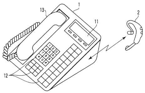
FIG. 1 is an exemplary outer appearance
illustrating a first embodiment of a telephone set and
a BT headset regarding the present invention;
FIG. 2 is an exemplary block diagram illustrating
a circuit configuration of a telephone set main body in
the first embodiment of the present invention;
FIG. 3 is an exemplary view illustrating one
example of storage contents of a storage unit shown in
FIG. 2;
FIG. 4 is an exemplary block diagram illustrating
a configuration example of a voice processing unit
shown in FIG. 2;
FIG. 5 is an exemplary view illustrated for
explaining an example of a variable width specification
of a reception gain and a volume controller based on
CA 02567677 2006-11-09
- 5 -
the conventional art;
FIG. 6 is an exemplary view illustrated for
explaining an example of a variable width specification
of a reception gain and a volume controller applied to
the first embodiment of the present invention;
FIG. 7 is am exemplary block diagram illustrating
a configuration in the case in which an echo canceller
is included in a voice processing unit as a second
embodiment of the present invention; and
FIG. 8 is an exemplary block diagram illustrating
a configuration in the case in which a noise canceller
is included in a voice processing unit as a third
embodiment of the present invention.
DETAILED DESCRIPTION OF THE INVENTION
Various embodiments according to the invention
will be described hereinafter with reference to the
accompanying drawings.
(First Embodiment)
FIG. 1 is an outer appearance view showing a first
embodiment of a telephone set and a BT headset
regarding the present invention.
In FIG. 1, a BT headset 2 as a voice input/output
device is connected to a telephone set main body 1 by
radio. A display unit 11 using an LCD, etc., is
arranged on a front panel part of the telephone set
main body 1, further, a key matrix 12 composed of a
dial key, a function key, etc., is disposed on a lower
CA 02567677 2006-11-09
- 6 -
panel part of the display unit 11. A handset 13 with a
loud-speaker and a microphone is arranged on the left
side of the front panel part of the telephone set main
body 1.
On the other hand, a circuit configuration of the
telephone set main body 1 is described as follows.
FIG. 2 is a block diagram showing the configuration.
As shown in FIG. 1, the telephone set main body 1
includes an external interface (I/F) unit 101, a voice
processing unit 102, a voice interface unit 103, a
serial interface unit (S I/0) 104, a BT unit 105, a
main control unit 106, and a storage unit 107.
The external interface unit 101 conducts an
interface processing relating to an internet protocol
(IP) network to which the external interface unit 101
is connected. That is, the external interface unit 101
extracts voice data and control data from a
transmission packet transmitted from the IP network to
transfer the voice data to the voice processing unit
102 and the control data to the main control unit 106.
The external interface unit 101 multiplexes the data
supplied from the main control unit 106 onto the voice
data supplied from the voice processing unit 102 to
transmit it to the IP network.
The voice processing unit 102 amplifies the voice
data supplied from the external interface unit 101 by a
prescribed level to supply it to the voice interface
CA 02567677 2006-11-09
- 7 -
unit 103 and the serial interface unit 104. The voice
processing unit 102 amplifies transmission voice data
input from the voice interface unit 103 and the serial
interface unit 104 by a prescribed level to supply it
to the external interface unit 101.
A handset 13 and a telephone set, loud-speaker,
and microphone 14 are connected to the voice interface
unit 103. After digital-converting the transmission
voice signal input from the microphone of the handset
13 or the telephone set, loud-speaker and microphone 14
into transmission voice data, the voice interface unit
103 inputs it to the voice processing unit 102. After
analog-converting the reception voice data output from
the voice processing unit 102, the voice interface unit
103 acoustically reproduces it from the loud-speaker of
the handset 13 or the telephone set, loud-speaker and
microphone 14.
The BT unit 105 is connected to the serial
interface unit 104. The BT unit 105 communicates to
and from the BT headset 2 via the radio communication
line, transmits an authentication request to the BT
headset 2 and also receives a BT address and BT
registered name information transmitted from the BT
headset 2 in response to the authentication request to
register the registered name information. Further, the
BT unit 105 transmits the reception voice signal and
receives the transmission voice signal transmitted from
CA 02567677 2006-11-09
- 8 -
the BT headset 2. The registered name information
registered in the BT unit 105 is read out by the main
control unit 106.
The serial interface unit 104 digital-converts the
transmission voice signal input from the BT unit 105
into the transmission voice data then inputs it to the
voice processing unit 102. After analog-converting the
reception voice data output from the voice processing
unit 102 into the reception voice signal, the serial
interface unit 104 outputs it to the BT unit 105.
Thereby, the reception voice signal is supplied to the
BT headset 2 from the BT unit 105 via the radio
communication line to be acoustically reproduced from
the loud-speaker of the BT headset 2.
In the storage unit 107, as shown in FIG. 3,
stores transmission gain correction values and
reception gain correction values which accord with
communication volume standards when the BT headset 2
which has been already performance-confirmed is
connected to the telephone set main body 1 together
with the "BT registered name" of the BT headset 2. In
usual, since the BT headset 2 which has been already
performance-confirmed are present plurally,
transmission gain correction values and the reception
gain correction values are stored for each BT headset
2. Here, this storage is called a headset list. For
instance, it means that the BT headset 2 having a BT
CA 02567677 2006-11-09
- 9 -
registered name of "A" increases the transmission gain
by 6 dB, and the reception gain of the BT headset 2
accords with the communication volume standard without
any correction.
The main control unit 106 conducts control of each
part of the telephone main body 1 and a communication
processing to and from the IP network by means of a
software processing. When the sound volume value
setting from the user is accepted through the key
matrix 12, the main control unit 106 makes the voice
processing unit 102 adjust the sound volume value of
the loud-speaker volume controller to the set volume
value. The main control unit 106 makes the display
unit 11 display the adjusted result. The main control
unit 106 may use turning on or turning on and off of
the LED, etc.
The main control unit 106 reads out the BT
registered name information from the BT unit 105, and
compares the BT registered name information with the BT
registered name information stored in the storage unit
107. When both information matches with each other,
the main control unit 106 reads out the corresponding
transmission gain correction value and the reception
gain correction value. The main control unit 106 then
controls amplification gains of a reception amplifier
and a transmission amplifier in the voice processing
unit 102 based on the transmission gain correction
CA 02567677 2006-11-09
- 10 -
value and the reception gain correction value.
Next to this, operations in the foregoing
configuration will be set forth.
At first, when the BT headset 2 desired to be
connected and the telephone set main body 1 are paired,
the BT registered name of the BT headset 2 is
registered in the BT unit 105. The main control unit
106 reads out the information on the registration to
check with the BT headset list in the storage unit 107.
If there are the identical registered names, the main
control unit 106 coordinates the transmission amplifier
gain and the reception amplifier gain of the voice
processing unit 102 with the correction values in the
BT headset list to change them. Thereby, the connected
BT headset 2 reaches such a level to match with the
communication volume standard without having to perform
a level adjustment.
Regarding the setting of the level will be
described in a little more detail hereinafter.
FIG. 4 is a configuration example of the voice
processing unit 102. A reception gain RXG is a sum of
a gain RX of a reception amplifier 1021 and a gain VOL
of a volume controller 1022. A gain TX of a
transmission amplifier 1023 is a gain thereof as it is.
For example, sensitivity of a loud-speaker of the
BT headset 2 with the BT registered name "X" is low,
and the reception gain has to be increased by 4 dB when
CA 02567677 2006-11-09
- 11 -
the BT headset 2 is connected to the telephone set main
body 1. In contrast, the transmission level being a
little bit high, the transmission level should be
decreased by 2 dB so as to match with a communication
level reference.
As one of conventional methods, there is a method
for increasing the reception level by operating a
volume button in the key matrix 12 of the telephone set
main body 1. This method sets the volume controller
1022 to +4 dB. (a) and (b) of FIG. 5 each show the
reception gains RXGs and the volume variable widths.
This cannot change the transmission gain.
Therefore, the present invention changes the gain
RX of the reception amplifier 1021 and the gain TX of
the transmission amplifier 1023. In this case, the
reception gain RX is increased by 4 dB because the
reception is increased by 4 dB, and the transmission
gain TX is decreased by 2 dB because the transmission
is decreased by 2 dB. (a) and (b) of FIG. 6 each show
the reception gains RXGs and the volume variable
widths. This method can correct both transmission and
reception. Even a device the volume value of which
returns to the default values for each communication,
it accords with the communication volume standard. In
adjusting the volume controller 1022, as shown at (c)
of FIG. 6, the gain RX of the reception amplifier 1021
is set to "0". Thereby, the setting becomes easy when
CA 02567677 2006-11-09
- 12 -
the BT headset 2 is connected to the telephone set main
body 1.
As mentioned above, in the first embodiment, the
registered name information, the transmission gain
correction values, and the reception gain correction
values of the BT headset 2 to be connected are
associated with one another to register them in the
storage unit 107 of the telephone set main body 1.
When the BT headset 2 is connected through the BT unit
105, the BT registered name information is acquired
from the BT headset 2 to register it by using the
authentication procedure on the radio communication
lime. The main control unit 106 then reads out the
transmission gain correction value and the reception
gain correction value corresponding to the BT
registered name information to control each gain of the
reception amplifier 1021 and the transmission amplifier
1023 of the voice processing unit 102 based on the
transmission gain correction value and the reception
gain correction value.
Accordingly, in the case in which the BT headset 2
like the Bluetooth via the radio communication line,
the BT headset 2 can automatically set an optimum
communication level without individually setting
through manual operations by the user.
(Second Embodiment)
FIG. 7 is a block diagram showing a configuration
CA 02567677 2006-11-09
- 13 -
of a voice processing unit 102 in a second embodiment
of the present invention. In FIG. 7, the same
components as those of FIG. 4 are designated by the
identical symbols and their detailed descriptions are
eliminated.
That is to say, an echo canceller and an adder 32
are interposed between the output side of the volume
controller 1022 and the input side of the transmission
amplifier 1023.
The echo canceller 31 inputs an output signal from
the volume controller 1022 to generate a signal to
remove acoustic echoes added to the input signal from
the transmission amplifier 1023. The output signal
from the echo canceller 31 is added to the output
signal from the serial interface 104 through the adder
32 then the acoustic echoes added to the transmission
voice signal are reduced.
Next, operations in the aforementioned
configuration will be described.
The BT headset 2 is miniaturized and lightened, so
that some BT headsets 2 have adverse affects, such as
acoustic coupling that is creeping of sounds from a
loud-speaker because the loud-speaker and the
microphone are positioned close to each other and
surrounding noise is easily picked because the
microphone is positioned too close to an ear and away
from the mouse of a speaker, on communication
CA 02567677 2006-11-09
- 14 -
performance resulting from the miniaturization.
For the user of such BT headset 2, providing the
echo canceller 31 for the voice processing unit 102 in
the telephone set main body 1 makes it possible for the
BT headset 2 to complement poorness of the performance
thereof.
As given above, in the second embodiment, the
transmission voice signal having been amplified by the
transmission amplifier 1023 after the cancellation of
the acoustic echoes by the echo canceller 31, the
acoustic echoes added to the transmission voice signal
may be further reduced.
(Third Embodiment)
FIG. 8 is a block diagram depicting a
configuration of a voice processing unit 102 in a third
embodiment of the present invention. In FIG. 8, the
same components as those of FIG. 4 are designated by
the identical symbols and detailed descriptions are
eliminated.
That is, a noise canceller 41 and an adder 42 are
interposed on an input side of the transmission
amplifier 1023.
The noise canceller 41 inputs an output signal
from the serial interface unit 104 to generate a signal
to remove noises added to the input signal to the
transmission amplifier 1023. The output signal from
the noise canceller 41 is added to the output signal
CA 02567677 2006-11-09
- 15 -
from the serial interface unit 104 by the adder 42 then
the noises added to the transmission voice signal are
reduced.
As given above, in the third embodiment, the
transmission voice signal having been amplified by the
transmission amplifier 1023 after the cancellation of
the noises by the noise canceller 41, the noises added
to the transmission voice signal may be further
reduced.
(Other Embodiment)
The present invention is not limited to the
foregoing each embodiment. For instance, in the second
and third embodiments, it is more preferable that the
echo canceller and noise canceller are not used if
possible in terms of an increase in bottom noise. Some
relatively expensive BT headsets prevent the acoustic
coupling by mounting the loud-speaker in a different
house form that of the microphone, or make it hard to
pick the surrounding noises by suing a microphone unit
of a noise canceling type. It is much better for the
headset taking such measures not to operate the echo
canceller and noise canceller. Conventionally, a
telephone set having separately set the operation/non-
operation of the echo canceller and noise canceller,
according to the present invention, storing the
operation/non-operation of the echo canceller as items
of the headset list makes the setting unnecessary in
CA 02567677 2006-11-09
- 16
-
the case of accordance of the BT registered name.
In the aforementioned each embodiment, the
telephone set connected to the IP network having
described as an example, the present invention is not
limited to the embodiments and may be applied to a
telephone set to be connected to an analog line.
In each embodiment, the present invention may also
be applied to a personal computer with a telephone
application mounted thereon and electronic equipment
treating a voice signal. The present invention may be
applied to a voice input/output device other than a
headset to be connected via the radio communication
line.
Other than this, various modifications of types
and their configurations of terminal devices such as
telephone sets, types of headsets, and kinds of
communication level setting values such as transmission
gain correction values and reception gain correction
values may be made within a range not departing from
the principle of the present invention.
Additional advantages and modifications
will readily occur to those skilled in the art.
Therefore, the invention in its broader aspects is not
limited to the specific details and representative
embodiments shown and described herein. Accordingly,
various modifications may be made without departing
from the spirit or scope of the general inventive
CA 02567677 2006-11-09
- 17 -
concept as defined by the appended claims and their
equivalents.