Note: Descriptions are shown in the official language in which they were submitted.
CA 02567780 2011-10-14
CONFORMAL VACUUM CUP APPARATUS AND METHOD FOR
REMOVABLY ATTACHING A RAIL TO A SURFACE OF A WORKPIECE
FIELD OF THE INVENTION
[0001] The present invention relates generally to manufacturing tools and
automation. More particularly, the present invention relates to attachment of
rail-mounted
machine tools to work surfaces.
BACKGROUND OF THE INVENTION
[0002] Portable, vacuum-cup-attached systems for drilling or fastening
sections of
aircraft fuselage or wing structures, as well as for other manufacturing
operations, for other
vehicle types, and for static structures, have been developed previously, but
have generally
been most practical for use only on workpiece areas where the contour is zero
or very small
in the longitudinal direction of the device. For example, some prior art
vacuum cup systems
could be attached readily along the flight direction of a cylindrical or
otherwise highly curved
fuselage, particularly where the fuselage has a long, essentially straight
extent (i.e., a contour
near zero), but attaching such a system to the fuselage in the circumferential
direction, or
fore-and-aft along a curving wing rib, would tend sometimes to produce
uncertain results.
[0003] Prior art systems that use small numbers of large vacuum cups have been
used, but have tended to be unable to conform smoothly to severe contours.
Prior art systems
with large numbers of small vacuum cups can follow a contour to some extent,
but tend to be
limited in the available retaining force by the necessity of having physical
clearance around
each vacuum cup, and by the limited available length-to-width ratio of an
individual cup.
[0004] Prior art rail-mounted machine tool systems can possess the capability
to
advance a tool attached to a rail using a motor and gear apparatus integrated
with the tool.
Measurement apparatus, likewise integrated with the tool, allows the position
of the tool to
be determined with considerable precision. Nonetheless, prior art systems tend
to be limited
in their ability to conform to generalized surfaces, being best suited to
positioning along low-
contour paths.
AKT/3229779 - 1 -
CA 02567780 2006-11-22
WO 2006/043983 PCT/US2005/016085
[0005] Accordingly, it would be desirable to provide a method and apparatus
that
provides attachment of a rail system that can conform to surfaces with
comparatively large
contour in the longitudinal direction of traversal by the rail system and by
tools carried thereon.
SUMMARY OF THE INVENTION
[0006] The conformal vacuum cup described in some embodiments comprises a
resilient
cup member having a series of rigid stiffener elements oriented next to each
other along the
longitudinal axis of a rail system. A rail can be supported by attachment to
the stiffener
elements. The stiffener elements can be spaced away from the rail, in a
representative
embodiment, using standoff pins attached to the stiffener elements and to the
rail. Between each
pair of stiffener elements is a gap sufficient to allow the rail to flex over
a comparatively sharply
curved contour without interference. A group of stiffener elements assembled
in a mold can be
overmolded with an elastomeric material such as urethane, which overmolding
encloses all of the
stiffener elements and adds a circumferential lip to establish the vacuum cup.
The vacuum cup
so formed can have kerf shapes formed into the gaps between adjacent stiffener
elements to
permit substantial motion between the stiffener elements despite the presence
of the overmolded
elastomer. The above standoff pins can protrude from top and/or bottom
surfaces of the
overmolded elastomer.
[0007] In another aspect, a vacuum cup for removable connection between a
conformable, tool-carrying rail and a rail-side surface of a workpiece
comprises an inner surface
of the vacuum cup, an outer surface of the vacuum cup, a plurality of
resilient pads joined into a
contiguous whole (wherein the area between each pad and the rail-side surface
of the workpiece
defines a zone), a plurality of stiffener elements (wherein at least one of
the plurality of
stiffening elements is embedded at least partially within each respective one
of the pads, and
wherein the stiffener elements are attachable to the rail), and a resilient
peripheral seal, joined to
the pads and surrounding the periphery of all of the zones between the pads
and the rail-side
surface of the workpiece.
-2-
CA 02567780 2006-11-22
WO 2006/043983 PCT/US2005/016085
[0008] In still another aspect, a vacuum cup for removable connection between
a
conformable, tool-carrying rail and a rail-side surface of a workpiece
comprises an inner surface
of the vacuum cup, an outer surface of the vacuum cup, a plurality of
resilient pads joined into a
contiguous whole, wherein the area between each pad and the rail-side surface
of the workpiece
defines a zone, a plurality of stiffener elements, wherein one of the
plurality of stiffening
elements is embedded at least partially within each of the pads, and wherein
the stiffener
elements are attachable to the rail, and a resilient peripheral seal, joined
to the pads and
surrounding the periphery of all of the zones between the pads and the rail-
side surface of the
workpiece, and a plurality of standoff pins attached to the rail, where at
least one of one of the
standoff pins is attached to a respective one of each of the stiffener
elements.
[0009] In still another aspect, an attachment between a rail with a
longitudinal axis and a
rail-side surface of the workpiece comprises means for stiffening a vacuum cup
along an axis
transverse to the longitudinal axis of the rail and parallel to the rail-side
surface of the workpiece,
means for removably sealing the stiffening means to the rail-side surface of
the workpiece
against vacuum loss, means for rigidly positioning a point on the rail with
respect to a point on
the rail-side surface of the workpiece, and means for coupling a vacuum source
to a spatial
volume occupying all of a space between the means for sealing and the rail-
side surface of the
workpiece.
[0010] In yet another aspect, a method for removably attaching a rail with a
longitudinal
axis to a rail-side surface of a workpiece comprises stiffening a vacuum cup
along an axis
transverse to the longitudinal axis of the rail and parallel to the rail-side
surface of the workpiece,
removably sealing a perimeter of the vacuum cup to the rail-side surface of
the workpiece
against vacuum loss, rigidly positioning a point on the rail with respect to a
point on the rail-side
surface of the workpiece, and coupling a vacuum source to a spatial volume
occupying all of a
space between the vacuum cup and the rail-side surface of the workpiece.
[0011] There have thus been outlined, rather broadly, certain embodiments of
the
invention, in order that the detailed description thereof herein may be better
understood, and in
order that the present contribution to the art may be better appreciated.
There are, of course,
-3-
CA 02567780 2006-11-22
WO 2006/043983 PCT/US2005/016085
additional embodiments of the invention that will be described below and which
will form the
subject matter of the claims appended hereto.
[0012] In this respect, before explaining at least one embodiment of the
invention in
detail, it is to be understood that the invention is not limited in its
application to the details of
construction and to the arrangements of the components set forth in the
following description or
illustrated in the drawings. The invention is capable of embodiments in
addition to those
described and of being practiced and carried out in various ways. Also, it is
to be understood
that the phraseology and terminology employed herein, as well as the abstract,
are for the
purpose of description and should not be regarded as limiting.
[0013] As such, those skilled in the art will appreciate that the conception
upon which
this disclosure is based may be used readily as a basis for the designing of
other structures,
methods, and systems for carrying out the several purposes of the present
invention. It is
important, therefore, that the claims be regarded as including such equivalent
constructions
insofar as they do not depart from the spirit and scope of the present
invention.
BRIEF DESCRIPTION OF THE DRAWINGS
[00141 FIG. 1 is a perspective view illustrating from beneath a fully
compressed
conformal vacuum cup according to a preferred embodiment of the invention.
[0015] FIG. 2 is an oblique view from above with cutaway of a conformal vacuum
cup
according to the embodiment of FIG. 1.
[0016] FIG. 3 is an exploded view of an end stiffener and associated standoff
pins
according to the embodiment of FIG. 1.
[0017] FIG. 4 is an exploded view of an intermediate stiffener and associated
standoff
pins according to the embodiment of FIG. 1.
[0018] FIG. 5 is a section view of a vacuum connection with an intact
diaphragm.
[0019] FIG. 6 is a section view of a vacuum connection with a pierced
diaphragm in
which a barbed tubing coupling has been installed.
-4-
CA 02567780 2006-11-22
WO 2006/043983 PCT/US2005/016085
[0020] FIG. 7 is a side view with cutaway of a conformal vacuum cup installed
on a rail
and pressed onto a workpiece, according to the embodiment of FIG. 1.
[0021] FIG. 8 is a section view of a groove and kerfs separating two pads
according to
the embodiment of FIG. 1.
[0022] FIG. 9 is a section view of a groove without kerfs.
[0023] FIG. 10 is an oblique view from above of a conformal vacuum cup
according to
an alternative embodiment of the invention.
[0024] FIG. 11 is a side view of a multiplicity of conformal vacuum cups
according to
the alternative embodiment of FIG. 10, showing attachment to a rail and a
curved workpiece.
DETAILED DESCRIPTION
[0025] Various embodiments in accordance with the present invention provide
vacuum
cup apparatus and methods for attachment of devices such as, for example, a
rail system used in
operations such as drilling series of holes, which holes may be needed for
assembling screws or
rivets through airplane sheet surfaces into underlying structures. Although
described in the
context of aircraft manufacturing, various embodiments can also be useful in
other
manufacturing industries. The invention will now be described with reference
to the drawing
figures, in which like reference numerals refer to like parts throughout.
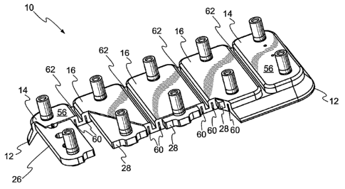
[0026] FIG. 1 is an oblique bottom view that shows a fully compressed vacuum
cup 10
according to an exemplary embodiment. The vacuum cup 10 has a peripheral
sealing lip 12 that is
shown deflected as it would be seen from below a transparent workpiece (a
workpiece 70 is shown
in FIGS. 7 and 11) when vacuum from an external vacuum system (shown in FIG.
10) has been
applied to the volume between the cup 10 and the workpiece 70, and has caused
outside air
pressure to force the cup 10 against the workpiece 70. The exemplary vacuum
cup 10 comprises
two end pads 14 along with three intermediate pads 16. Each pad 14 or 16
comprises a stiffener
(stiffeners 26 and 28 are shown in FIG. 2) encapsulated in the resilient
material of the vacuum cup
10, and further comprises two standoff pins 18 with bottom ends 20 that can
directly contact the
workpiece when the cup 10 is compressed. The standoff pin tops 22 can be
attached to a rail using
-5-
CA 02567780 2006-11-22
WO 2006/043983 PCT/US2005/016085
suitable fastenings (a rail 72 is shown in FIGS. 7 and 11). One or more
partial holes 24 that are
used to permit vacuum system attachment are shown in each end pad 14 and in
more detail in
FIGS. 5 and 6.
[0027] FIG. 2 is an oblique cutaway view of the vacuum cup 10 from above.
Representative pads 14 and 16 are shown cut away to reveal an end pad
stiffener 26 and
intermediate pad stiffeners 28 within their respective pads 14 and 16. Similar
stiffeners are fully
shown in FIGS. 3 and 4.
[0028] FIG. 3 is an oblique exploded view showing an end stiffener 30
substantially
similar to the corresponding stiffener 26 in FIG. 2. The stiffener 30 is shown
with two standoff
pins 18 oriented for insertion. Each of the exemplary standoff pins 18 in FIG.
3 has a pin top 22
with a chamfer 32 and a female thread 34 for attachment to a rail 72 (shown in
FIGS. 7 and 11).
A taper section 36 and an interference-fit section 38 on each standoff pin 18
can allow the pin 18
to be pressed substantially permanently into the corresponding hole 40. A
shoulder 42 can
provide an integral stop to allow the pin 18 to bear against the stiffener 26
or 30, with the pin
bottom end 20 at a uniform distance from the bottom surface 44 of the
stiffener 26 or 30. Three
bores 46 in the end stiffener 30 can be used to provide passage for vacuum
connection (shown in
FIGS. 5 and 6).
[0029] FIG. 4 is an oblique exploded view showing an intermediate stiffener 48
substantially similar to the corresponding stiffener 28 in FIG. 2. The
stiffener 48 is shown with
two standoff pins 18 oriented for insertion. Each of the pins 18 in FIG. 4 has
a pin top 22 with a
chamfer 32 and a female thread 34 for attachment to a rail 72 (shown in FIGS.
7 and 11). A
tapered section 36 and an interference-fit section 38 on each pin 18 can allow
the pin 18 to be
pressed essentially permanently into the corresponding hole 40. A shoulder 42
can provide a
stop that allows the pin 18 to bear against the stiffener 48, with the pin
bottom end 20 at a
uniform distance from the bottom surface 50 of the stiffener 28 or 48.
[0030] Returning to FIG. 2, the sealing lip 12 is shown relaxed and deflected
downward
in its rest orientation. Inscribed around most of the perimeter of each of the
pads 14 and 16 is a
kerf or lower slot 60. An upper groove or slot 62 is present as well. The two
kerfs 60 and one
-6-
CA 02567780 2006-11-22
WO 2006/043983 PCT/US2005/016085
groove 62 together provide some degree of decoupling between each two
stiffeners 26, 28, 30, or
48, allowing the stiffeners 26, 28, 30, or 48 to draw together or move apart
as flexed by the rail
72 (shown in FIGS. 7 and 11) to which they are fastened, and/or to twist
relative to each other if
so driven by the mounted curve profile of the rail 72.
[0031] FIG. 5 is a section through FIG. 1 at section line 5-5. This shows that
the first
partial hole 24 in the bottom face 52 of an end pad 14 aligns with a second
partial hole 54 in the
top face 56, shown in FIG 2, of the end pad 14. The two partial holes 24 and
54 are separated by
a diaphragm 58, and may preferably be positioned within one of the bores 46 in
the end stiffeners
26 and 30.
[0032] FIG. 6 is a section view of a barbed tubing coupling 64 inserted into a
vacuum
cup 10. After the diaphragm 58 has been pierced, for example using an ordinary
sewing needle,
a barbed coupling 64 of suitable size can be inserted into the second partial
hole 54. The barbed
coupling 64, preferably carrying a single barb on each end as shown,
preferably passes through
the pierced diaphragm 58 and uses the pierced diaphragm 58 as a locking
element to retain the
barbed coupling 64. Various options may be preferable in some applications,
such as using
multiple-barb ends on the barbed coupling 64 or passing the barbed coupling 64
through the
pierced diaphragm 58 and the first partial hole 24, although preferably not
extending the barbed
coupling 64 so far through the bore 46 as to extend beyond the pin bottom end
20 and contact the
workpiece 70. The top of the barbed tubing coupling 64 is shown to be set at a
right angle 66.
The right angle 66 shown may be preferable to allow a vacuum line 68 to
deliver vacuum to the
vacuum cup 10 without a sharp bend in the line 68. Other angles and other
fitting styles may be
preferable in some applications.
[0033] Returning once more to FIG. 1, the multiplicity of partial holes 24 in
the end pads
14 can be used to provide optional vacuum connections. In some embodiments it
may be
preferable to plumb all vacuum cups 10 individually back to a common manifold.
This can
permit a manifold with valving to apply vacuum systematically, for example
applying vacuum
first to vacuum cups 10 located near mid rail, then sequentially activating
cups outward toward
both ends.
-7-
CA 02567780 2006-11-22
WO 2006/043983 PCT/US2005/016085
[0034] Experimentation has shown that for at least some combinations of
materials and
dimensions, a pierced diaphragm 58 may leak substantially no air when no
barbed coupling 64
has been installed in it. This can allow the vacuum cup 10 in which the
pierced diaphragm 58
exists to hold vacuum acceptably. By extension, a vacuum cup 10 may remain
usable with
multiple diaphragms 58 that are unused but have been pierced.
[0035] Since the baseline configuration for the exemplary embodiment employs a
common area below the entire vacuum cup 10, vacuum drawn at a first pierced
partial hole 24
can be extended out through a second pierced partial hole 24 (as shown in FIG.
10). Another
barbed tubing coupling 64 can be added to connect the vacuum source to a
second vacuum cup
10 without using a manifold port at the vacuum source for every vacuum cup 10.
Providing an
ample number of partial holes 24 in the embodiment permits a variety of
options for distributing
vacuum in a rail-mounted machine tool system with a vacuum cups 10 of a single
design. The
availability of additional partial holes 24 can permit the addition of
sensors, gauges, and the like
as well as additional vacuum cups 10.
[0036] Continuing in FIG. 1, the standoff pins 18 are shown surrounded by the
elastomer
of the pads 14 and 16. The pin bottom ends 20 can be domed with a radius
roughly equal to the
elastic deformation of the workpiece 70 effected by the pressure stemming from
the applied
vacuum plus a portion of the weight of the rail-mounted drilling system. If
the elastic
deformation of the workpiece 70 can be shown to be negligible, then a
satisfactory pin bottom
end 20 shape may be achievable with a flat face square to the workpiece and a
smooth edge
roundoff. The pin bottom end 20 shape, radius of curvature, and size may
preferably be chosen
to at least minimize scuffing or marring of the workpiece 70.
[0037] FIG, 7 is a side view with a partial cutaway, revealing the structure
of a vacuum
cup 10 pressed against a workpiece 70 and attached to a rail 72 with studs 74,
nuts 76, and
washers 78. The lip 12 is flexed upward from its rest position as a result of
application of
vacuum. In FIG. 7, a flat workpiece 70 is contacted by the standoff pins 18,
causing the rail 72
to assume a flat shape, parallel to the workpiece 70.
-8-
CA 02567780 2006-11-22
WO 2006/043983 PCT/US2005/016085
[0038] FIG. 8 is a section through the vacuum cup 10 of FIG. 1, in which the
kerfs 60
and upper groove 62 are shown as they would be with a vacuum cup 10 positioned
on a flat
workpiece 70. Where the workpiece 70 surface is curved, the standoff pins 18
(shown in FIGS. 1
and 2) are drawn by the vacuum to conform to that curve, shifting the
stiffeners 28 and 30, and
causing the elastomer between the kerfs 60 and the upper groove 62 to flex.
This flexure allows
the vacuum cup 10 to conform to a workpiece 70 with a relatively sharp
curvature, and thus to
cause the rail 72 to so conform. Twist in the workpiece 70 can be accommodated
as well, with
the elastomer flexing as necessary.
[0039] FIG. 9 is a section through an alternative vacuum cup configuration
retaining the
upper groove 62 but without kerfs. This configuration may be preferable on
some workpieces,
for example where curvature is slight or nonexistent along the rail
longitudinal axis.
[0040] Alternative methods for fastening standoff pins to a rail could include
welding,
brazing, and equivalent metallurgical bonding methods, as well as application
of a flange to the
top of each standoff pin, which flange could have multiple radially-arrayed
holes for rivets or
other fastenings. The stud 74, nut 76, and washer 78 of the exemplary
embodiment can be
replaced by other threaded fasteners, such as screws with or without washers,
and can be
prevented from loosening by application of antivibration materials, upset
threads, and other
technologies.
[0041] FIG. 10 is an oblique view of a conformal vacuum cup 10 according to
another
design. Here, the lip 12 is made wavy instead of straight-edged as in FIGS. 1-
9. In the
embodiment shown, the elastomeric material 80 does not surround the stiffeners
28 and 30 above
an attachment shoulder 82. The embodiment shown has one inlet vacuum line 84
and one outlet
vacuum line 86, with no provision for additional vacuum lines. In this
embodiment, a fitting 88 is
employed to seal to a threaded hole and connect to a vacuum hose 94 at an
approximate right
angle. FIG. 10 further shows in schematic form the use of a vacuum source 92
connected by a
vacuum hose 94 to use the vacuum cup 10. In the embodiment shown, a second
fitting 88 connects
to a second vacuum hose 86 to carry vacuum to another vacuum cup 10 or to an
accessory such as
a gauge.
-9-
CA 02567780 2006-11-22
WO 2006/043983 PCT/US2005/016085
[0042] FIG. 11 shows multiple samples of the conformal vacuum cup 10 of FIG.
10
attached to a curved rail 72 using studs 74, nuts 76, and washers 78. Also
shown is a convex-
curved workpiece 70. The curvature of the rail 72 requires the flexing of the
conformal vacuum
cups 10 to accommodate the drawing together of the individual stiffeners 30
and 48 shown in
FIGS. 3 and 4.
[0043] The stiffeners 26, 28, 30, and 48 described herein can preferably be
fabricated
from a material with specific physical properties. One such desirable
stiffener property is higher
flexure resistance than the rail 72 and/or the workpiece 70, particularly in
the thickness used.
Another such desirable stiffener property is compatibility with insertion of
pins 18, which
compatibility includes adequate malleability to permit pin 18 insertion and
similarity in
temperature coefficient of expansion to the pins 18. Another such desirable
stiffener property is
compatibility with the elastomeric overmolding material, which compatibility
includes tolerance
of the temperatures at which the molding takes place and chemical
compatibility with the
overmolding material. Typical materials likely to be suitable include various
aluminum and
stainless steel alloys, fiber reinforced phenolics, engineering plastics such
as PEEK , and others.
[0044] Suitable elastomers for the vacuum cup overmolding material include a
class of
synthetic rubbers known generically as urethanes. Other classes of elastomers,
such as vinyls, as
well as other formable materials, may, like urethanes, have adequate ranges of
durometer values
and acceptable physical properties such as tear resistance for repeated use
and may exhibit an
ability to withstand rough treatment. Urethanes in the preferred range of
durometers can in some
formulations exhibit a desirable ability to cling to surfaces, which ability
may add to the
positioning force of the vacuum cups 10. Vinyls may exhibit significantly
lower cling than
urethanes, which may be preferable in some embodiments. Other elastomers may
likewise
exhibit desirable combinations of attributes for specific uses.
[0045] Forcing air, such as from a compressor, through a vacuum cup system may
allow
the cups to function as air bearings to make tool repositioning easier and
quicker. Specific
features such as lip shape, interface surface profile, elastomer material
choice, and available air
flow rate may inhibit or facilitate such use.
-10-
CA 02567780 2006-11-22
WO 2006/043983 PCT/US2005/016085
[0046] The many features and advantages of the invention are apparent from the
detailed
specification, and, thus, it is intended by the appended claims to cover all
such features and
advantages of the invention which fall within the true spirit and scope of the
invention. Further,
since numerous modifications and variations will readily occur to those
skilled in the art, it is not
desired to limit the invention to the exact construction and operation
illustrated and described,
and, accordingly, all suitable modifications and equivalents may be resorted
to that fall within
the scope of the invention.
-11-